Capacitors · Volume 10
Old Paper Capacitors and Why They Must Be Replaced
10.1 The component whose failure mode is time
Most components in a piece of electronics fail because something went wrong. A resistor cooks because a fault upstream pushed too much current through it; a transistor dies because it saw a voltage it was never meant to see. The old paper capacitor is different, and understanding why is the whole point of this volume. It fails because of nothing in particular. It fails because time passed. Left in a drawer, never wired to anything, kept cool and dry and idle, a paper capacitor made in 1955 is very probably bad today — not damaged, not abused, simply old in a way that, for this one component, is fatal. That is an unusual and slightly unsettling property for a part to have, and it is the reason a vintage radio, television, guitar amplifier, or piece of test gear cannot simply be plugged into the wall after fifty years in an attic and switched on. Somewhere on that chassis is a paper capacitor that has quietly turned into a resistor, and it is waiting to do expensive damage.
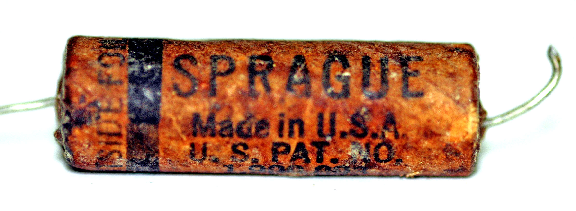
This is the component that gave the hobby of vintage electronics restoration its defining ritual — “recapping,” the wholesale replacement of a machine’s capacitors before it is ever powered up. To a newcomer the practice can look like superstition, or like the reflexive part-swapping of someone who does not know how to diagnose. It is neither. It rests on a piece of physics that is genuinely a certainty rather than a probability, and on a failure mode with a specific, well-documented, and costly consequence. What follows is what a paper capacitor is, exactly why age destroys it, what a bad one does to the machine around it, how to recognise the infamous offenders on sight, the genuine safety hazard hiding inside some of the larger oil-filled types, how to test rather than guess, and how to do the replacement properly. The short version can be stated up front, because it is the single most useful sentence a restorer will ever internalise: in vintage tube-era gear, assume every paper capacitor is bad until you have proven otherwise, and prove it before you apply power, not after.
10.2 What a paper capacitor actually is
For roughly the first half of the twentieth century, the paper capacitor was the fixed capacitor. When a schematic from the 1920s through the 1960s calls for a few hundredths of a microfarad — a coupling capacitor between two amplifier stages, a bypass across a cathode resistor, a filter across the power supply, the little “condenser” wired across a set of ignition points — the physical part that filled that role was almost always a roll of paper and metal foil. (The older word condenser, still stamped on tube-era schematics and service manuals, means exactly the same thing as capacitor; the naming history is told in the volume on the capacitor’s history.) Ceramic discs handled the very small values, mica handled the precision radio-frequency work, and electrolytics handled the big power-supply reservoirs, but the broad middle ground of general-purpose capacitance belonged to paper.
The construction is simplicity itself, which was much of its appeal. Take two long ribbons of thin metal foil — the two plates — and separate them with two ribbons of thin kraft paper, the same fibrous material as a grocery bag but made to a controlled thickness. The paper is the dielectric, the insulating filling that the electric field is stored in. Lay them up as a four-layer sandwich — foil, paper, foil, paper — attach a lead wire to each foil, and roll the whole stack up into a tight cylinder, exactly the way a modern film capacitor is still wound today. Two paper layers are used rather than one so that a single weak spot or pinhole in one sheet does not line up with a weak spot in the other and hand the two foils a direct short. The finished roll is then dried and impregnated — soaked, under heat and vacuum, with molten wax or with a special oil — and sealed inside a case.
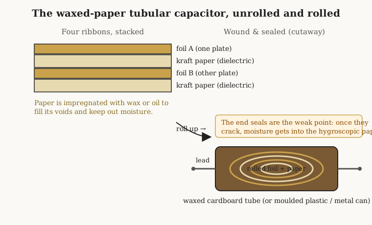
That impregnation step is not a detail — it is the entire life story of the part. Dry kraft paper on its own is a mediocre and unstable dielectric: it is full of microscopic air voids that lower its breakdown voltage, and it is hygroscopic, meaning it drinks water vapour straight out of the air. The wax or oil is there to drive the moisture out, fill the voids, raise the working voltage, and then seal the whole roll away from the atmosphere. A fresh, properly impregnated, properly sealed paper capacitor is a perfectly good component; when they were new, the best of them were the finest tubular capacitors money could buy. Everything that goes wrong later is the story of that seal failing and the atmosphere getting back in.
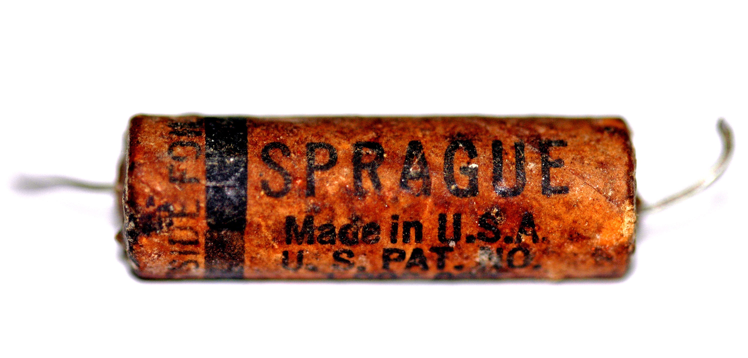
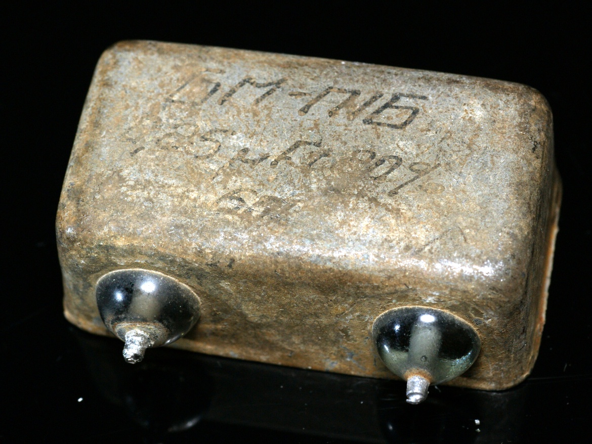
The cases came in several forms, and knowing them helps a restorer date and judge a part at a glance. The commonest is the waxed cardboard tube: a rolled-paper capacitor slid into a cardboard sleeve and dipped in wax, with the value and an end-band printed on the outside. These are the ubiquitous brown or beige “tubulars” that carpet the underside of any tube radio. A more upmarket version moulded a hard plastic or Bakelite shell directly around the roll — smarter-looking, and, as it turns out, often worse. And the highest grade sealed the roll inside a soldered metal can filled with oil, hermetically closed against the air; these paper-in-oil (PIO) types were the most durable of the family and are the ones most likely to still measure well today.
10.3 Why they fail: the certainty, not the risk
Here is the physics, and it is worth getting exactly right because it explains both the inevitability of the failure and the specific way a bad cap misbehaves.
Over decades, the seal gives up. Wax shrinks, hardens, and cracks with thermal cycling; the moulded shells develop microscopic fissures; even a soldered can can weep at a lead. Once the seal is breached, the paper’s hygroscopic nature does exactly what it always wanted to do: it absorbs moisture from the air. Water is a catastrophe for a dielectric. It has a very high permittivity but, far more importantly, it is slightly conductive and it carries dissolved ions, and it turns the once-insulating paper into a leaky, partly-conductive medium. The capacitor’s insulation resistance — the resistance measured across the dielectric, between the two plates, which in a good part should be hundreds or thousands of megohms — collapses. As insulation resistance falls, leakage current rises: a direct current that flows straight through a capacitor that is supposed to block direct current entirely. At the same time the dissipation factor (DF, a measure of how much energy the capacitor wastes as heat each cycle, treated at length in the volume on the real, non-ideal capacitor) climbs, because a lossy, damp dielectric is a poor one.
The cruel part, and the reason so many beginners get caught, is what all this does not do. It does not, at first, change the capacitance much. A leaky paper capacitor will still read close to its marked value on a cheap capacitance meter or a digital multimeter’s capacitance range, because those instruments measure the part with a small, low-voltage AC signal and report the value they compute — they do not, and cannot, see the leakage that only reveals itself under real working voltage. So the newcomer measures the old cap, sees “0.047 µF, near enough,” pronounces it good, and puts it back. It is not good. It has the right capacitance and the wrong everything-else. It has become, in effect, a capacitor with a resistor secretly wired across it, and that hidden resistor is what does the damage.
This is why the correct mental model is not risk but certainty. Ceramic and mica caps from the same era are usually fine; film caps, when they eventually appear, are essentially immortal. But paper is hygroscopic and its seals were never going to last a human lifetime, so the failure is not a matter of whether but of how far along. A given fifty-year-old paper capacitor might be slightly leaky or grossly leaky, but the population as a whole is bad, and the sensible restorer treats every one of them as guilty. Replacing a paper cap that happened to still be acceptable costs a dollar and ten minutes; leaving in a bad one can cost a great deal more, which brings us to the actual damage.
10.4 What a leaky cap does: the coupling capacitor and the red plate
The reason recapping is not optional — the reason it is the first thing done rather than a nicety — is a specific and destructive chain of events involving the most critical paper capacitor in any tube amplifier or radio: the coupling capacitor.
A coupling capacitor sits between two amplifying stages. Its job is to pass the alternating-current audio (or radio) signal from the plate of one tube to the grid — the control input — of the next, while blocking the direct current. This blocking is essential, because the two points it connects sit at wildly different DC voltages. The plate of the driving tube might sit at a couple of hundred volts positive with respect to ground (the high-voltage supply in tube gear is universally called B+). The grid of the following tube, by contrast, must sit at a small negative voltage relative to its cathode — its “bias” — so that the tube idles cool and conducts current only in response to the signal. In a typical output stage that bias might be somewhere in the region of minus fifteen to minus sixty volts. The coupling capacitor’s entire reason for existing is to let the signal cross that gap while keeping the driver’s high positive plate voltage from ever reaching the sensitive grid.
Now make that capacitor leaky. The barrier is no longer perfect. A trickle of direct current bleeds through the degraded paper, carrying some of the driver’s positive plate voltage onto the grid it was supposed to be protecting. The grid, which should be sitting comfortably negative, drifts toward zero and then positive. A control grid driven positive is a tube’s throttle jammed open: the tube conducts far more current than it was ever meant to, continuously, with no signal present at all.
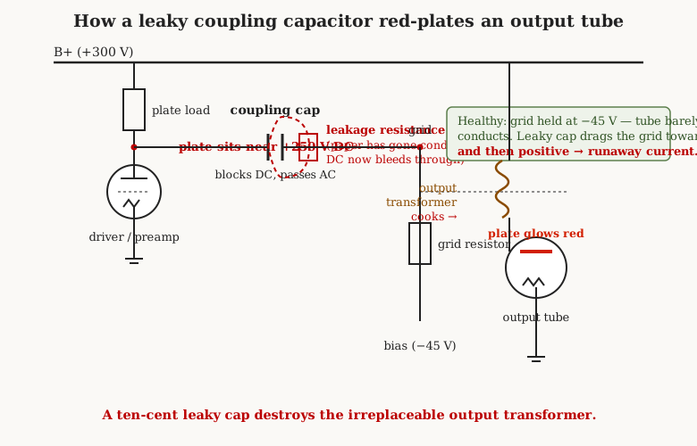
In an output tube, the consequences are visible and then audible and then terminal. The plate — the large internal electrode — begins to dissipate far more power than it is rated for, and it heats up until it glows a dull, then a bright, cherry red. This is the notorious “red-plating,” and any restorer who has seen it through the ventilation holes of an amplifier has felt the accompanying lurch of dread, because it means money is being destroyed in real time. The excessive current has to flow somewhere, and it flows through the components in series with that plate — most importantly the output transformer, the heavy iron-cored part that matches the tube to the loudspeaker. Output transformers, especially the originals in a vintage amplifier, are frequently the single most expensive and least replaceable component in the whole machine; many were custom-wound and are simply unobtainable today. A red-plating tube cooks the transformer’s fine winding insulation until it shorts, or it burns up the cathode-bias resistor, or it eventually destroys the tube itself. So the arithmetic that governs the whole hobby is this: a ten-cent capacitor, gone leaky purely through age, can and does destroy an irreplaceable part worth many times the value of the entire radio. That asymmetry is why nobody who knows better powers up an old amplifier on its original coupling caps to “see if it works.” Seeing if it works is exactly how the transformer dies.
Coupling caps are the headline case, but they are not the only leaky-paper story. A leaky cathode bypass or screen bypass capacitor upsets the operating point of its stage and can rob the amplifier of gain or drag a tube out of its intended bias. Leaky paper caps across the power supply waste current, run hot, hum, and stress the rectifier and filter. A leaky cap wired across the ignition points of an old engine’s magneto lets the points arc and burn. Every position has its own consequence; the coupling cap simply has the most expensive one, and it is the reason the rule is absolute rather than selective.
10.5 The infamous parts: knowing the offenders on sight
Restoration lore has a rogues’ gallery, and a working knowledge of it lets a restorer glance under a chassis and know what is waiting. The names below are worth memorising, because half of the recognition is simply knowing which shapes and colours to distrust.
The most famous are Sprague’s moulded tubulars, the Black Beauty and the Bumblebee. These are the same basic idea — a wound paper roll with hot Bakelite moulded directly around it — dressed up as a premium part. The “Bumblebee” (a collector’s nickname; Sprague never used it) wore painted colour bands around a black body, an EIA colour code meant to be readable no matter which way the capacitor was installed. The bands confused as many technicians as they helped, so Sprague reverted to printed lettering and the name “Black Beauty.” A useful identification detail, worth knowing: on the later printed ones, yellow printing generally denotes the paper dielectric, while red printing denotes the Mylar (polyester film) versions Sprague introduced later — and the red-printed film ones are far more likely to still be good. The bitter irony of the moulded types is that the very feature that made them look premium is what damns them. To mould hot Bakelite around a delicate oil-filled roll without crushing it, the roll had to be saturated and pressurised, and the moulding process left the shell prone to microscopic cracks. Through those cracks the impregnating oil slowly escapes, and once it is gone the bare paper reverts to a withstanding voltage well under two hundred volts — often far below the voltage it is sitting across in the circuit. When new, these were the best tubulars available and many outlived their nominal ten-year life handily; but by the time they are the age they are now, they test leaky more often than they test good, and in high-voltage line-bypass positions the worst of them have been known to burn. A collector’s beloved Black Beauty is, functionally, a near-guaranteed replacement.
The Micamold — despite a name that suggests mica — made moulded paper capacitors in the same vein, and they carry the same reputation. Then there is the loose category of small, flat, candy-shaped moulded caps that hobbyists call “chiclets,” and a caution attaches to it. A superficially similar striped, dipped part — the Philips/Mullard “tropical fish” and the related “mustard” caps — is frequently lumped in with the paper offenders because it looks like a colourful old cap, but those are actually polyester film and are generally reliable. Reading the markings correctly (the subject of the volume on decoding old capacitor codes) is what separates a genuine paper time-bomb from a perfectly good film cap that merely looks vintage; the lesson is to identify the dielectric, not just the vintage.
Finally, the paper-in-oil grades: Sprague’s “Vitamin Q,” the West-Cap hermetic types, and their kin, sealed in soldered metal cans. These are the aristocrats of the paper family and the ones most likely to still perform, because a true hermetic seal keeps the atmosphere out for far longer than wax ever could. Audiophiles prize surviving PIO caps for their sound. But “ages better” is not “cannot fail,” a sealed can that has finally been breached is just as leaky as any tubular, and — as the next section explains — some of these very oil types carry a hazard that the humble wax tubular does not.
10.6 Oil-filled caps and PCBs: a genuine safety matter
Not every old oil-filled capacitor is merely an electrical problem. Some are a chemical one, and this is the part of the volume that is about the restorer’s health rather than the equipment’s.
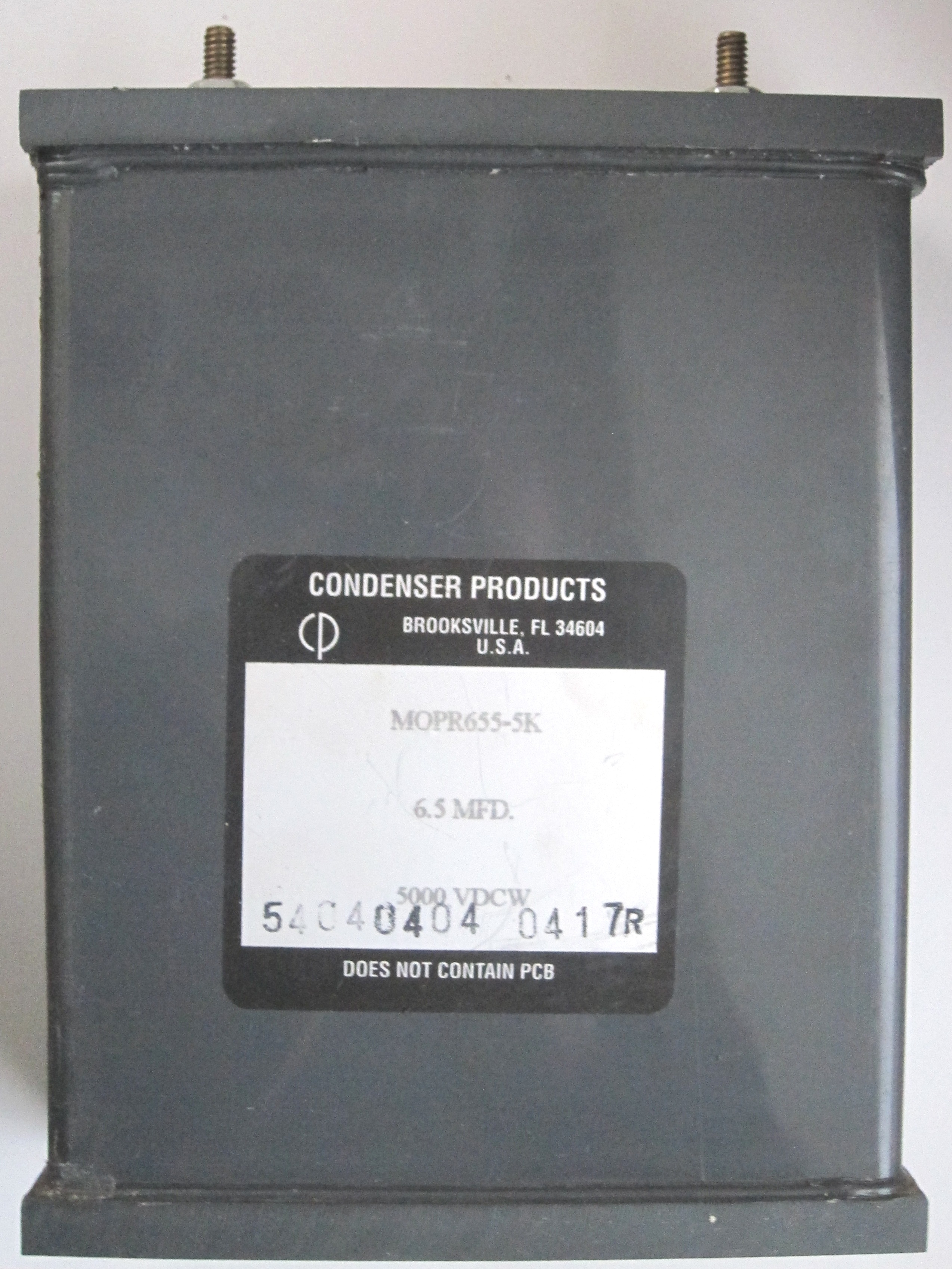
For much of the twentieth century the preferred impregnating and insulating fluid for larger oil-filled capacitors — and for the potted capacitors buried inside fluorescent-light ballasts, and for many motor-run and motor-start capacitors — was a class of synthetic liquids called PCBs, polychlorinated biphenyls, sold under trade names such as Askarel, Pyranol, Inerteen, and Aroclor. They were used precisely because they were excellent: chemically stable, superb insulators, and — the selling point — non-flammable, which let a capacitor or transformer be run hard without the fire risk of mineral oil. They were also, it turned out, a serious environmental toxin and a probable human carcinogen, they persist in the body and the environment for a very long time, and their manufacture was banned in the United States in 1979 under the Toxic Substances Control Act. The practical consequence for a restorer is a rule of thumb worth carrying: an oil-filled capacitor, ballast capacitor, or motor-run capacitor manufactured roughly between 1930 and the late 1970s may well contain PCB fluid, and the older and larger the oil-filled can, the more the suspicion applies.
This changes how such a part should be handled. A leaking oil-filled capacitor of that vintage — one that is weeping or that has burst — should be treated as a hazardous-material problem, not a soldering problem. It should not be cut open out of curiosity; the oil should not be handled with bare hands; and it should not be tossed in the household rubbish. In the United States, PCB-containing capacitors and ballasts are legally required to go to approved hazardous-waste disposal (ultimately high-temperature incineration), and there are reporting thresholds for larger quantities. The small waxed-paper tubulars under a radio chassis are not the concern here — they contain trivial amounts of wax or ordinary oil and are ordinary waste — but the big oil cans, and anything that came out of a mid-century fluorescent fixture or a motor, deserve respect and a trip to the proper disposal point rather than the bench vice. When in doubt, treat a leaking oil-filled cap of unknown vintage as if it contains PCBs and dispose of it accordingly.
10.7 Testing rather than guessing
The blanket “replace them all” rule is the right default, and for a restorer bringing a machine back to service it is usually the fastest path. But there are good reasons to actually measure — to confirm a diagnosis on a machine already running, to decide whether a rare hermetic PIO cap is worth keeping for originality, or simply to see the physics for oneself. The essential principle, and the thing that trips up everyone who reaches for a multimeter first, has already been stated but bears repeating in operational terms: capacitance is not the test. A leaky paper cap can read dead-on for value and still be junk. The test that matters is leakage current, or equivalently insulation resistance, measured at or near the capacitor’s actual working voltage.
The reason voltage matters is that the leakage of a degraded dielectric is strongly voltage-dependent — a cap that leaks imperceptibly at the few volts a DMM applies can conduct milliamps at the two or three hundred volts it faces in the circuit. So the meaningful measurement stresses the part at something like its rated working voltage and watches what current flows through it. In a good capacitor the answer is: essentially none, a brief charging surge and then a reading that climbs into the hundreds or thousands of megohms. In a bad one, current keeps flowing.
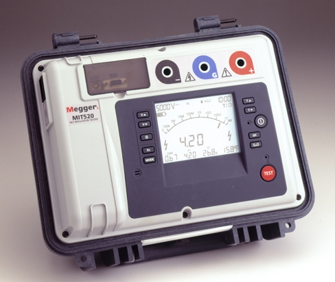
Several tools make this measurement. A dedicated insulation tester or megohmmeter (“megger”) applies a high DC test voltage — commonly a few hundred volts, some models more — and reads out the insulation resistance directly; it is the cleanest way to see leakage. The classic vintage-service instrument is the capacitor leakage tester, sometimes built into the old service “condenser checkers,” which does the same job at a selectable working voltage. And for the restorer without either, there is a simple bench method: charge the suspect capacitor through a known large resistor from a current-limited high-voltage source and measure the voltage across a sense resistor in series, or simply measure the steady-state voltage the capacitor settles to — any capacitor that will not hold off the applied voltage, that lets a persistent current flow, is leaky. (These measurements demand respect for the voltages involved; the volume on capacitor measurement covers instruments and safe technique in detail.) The interpretive rule for a coupling capacitor is unforgiving and simple: at working voltage, any meaningful, sustained DC leakage means replace. There is no acceptable trickle through a coupling cap, because there is no acceptable amount of the driver’s plate voltage to put on the next tube’s grid. For that critical position, guilty-until-measured-perfectly is the correct standard.
10.8 The fix: recapping done properly
Replacement is where the reader’s screwdriver actually earns its keep, and paper capacitors are, mercifully, one of the easiest kinds of restoration to get right. The correct modern replacement for a paper capacitor is a film capacitor — a capacitor built exactly like the old paper one, wound foil-and-dielectric, but with a plastic film in place of the kraft paper. Polyester (PET, often sold under the old trade name Mylar) is the workhorse choice for general coupling and bypass duty; polypropylene (PP) is preferred where lower losses or audiophile bragging rights are wanted. The film volume covers the material differences; for the restorer the headline is that a film cap does the identical job in the identical circuit position, is physically small and cheap, and — the whole point — does not have the paper cap’s fatal flaw.
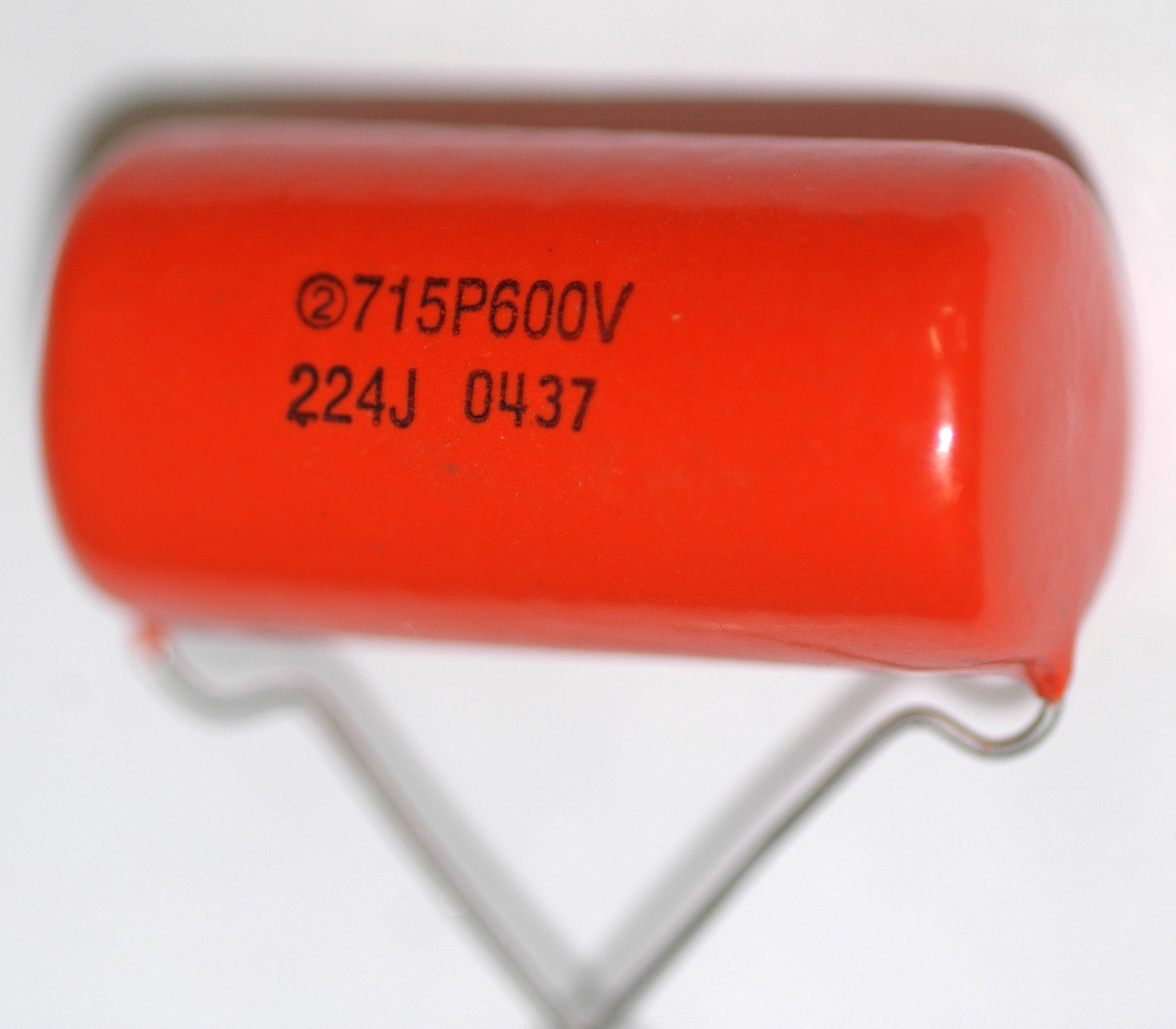
The single most popular replacement part deserves its own mention because the reader will hear the name constantly: the “orange drop,” originally a Sprague line and now a whole informal category of orange-cased polypropylene and polyester film capacitors. It became the default recap part for guitar amplifiers and radios through a combination of genuine quality, ready availability, and a look that has itself become a mark of a done-properly restoration. Any equivalent film cap of the right value and voltage works just as well; the orange drop is simply the one everyone reaches for.
The selection rules are straightforward. Match the capacitance to the original value — the marked number, decoded per the markings volume, not whatever a leaky measurement suggests. Match or exceed the voltage rating: a replacement rated for a higher working voltage than the original is always safe and often wise, since modern film caps rated at 400 or 630 volts are cheap and give generous margin in tube circuits where B+ can be high and transients higher. Going under the original voltage rating is the one genuine mistake to avoid. Paper coupling and bypass capacitors are non-polarised, so orientation does not matter electrically — but there is a lovely bit of old best-practice worth honouring where the original marked it: the band or stripe on the old cap indicated the outer-foil end, which was conventionally wired to the lower-impedance or ground side so that the outer foil acted as a bit of a shield. Preserving that orientation with the replacement, where the layout makes it easy, is a small nod to doing the job the way the factory intended.
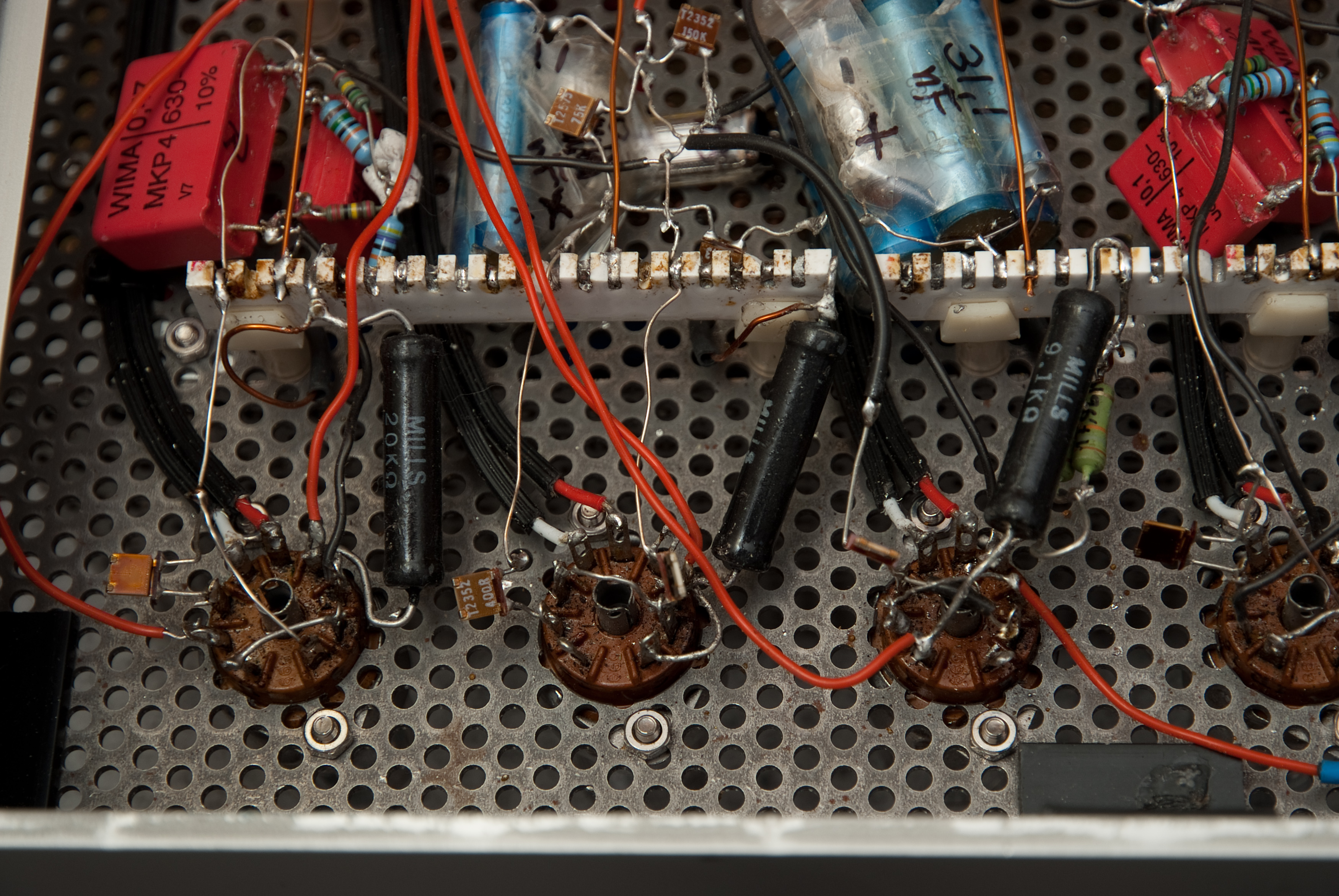
There is a genuine debate the restorer will encounter, and it is worth understanding rather than taking sides on: restuffing. A collector who cares about originality — a museum piece, a concours restoration, a rare amplifier whose value depends on looking untouched — may be unwilling to see a chassis full of modern orange drops where the factory installed Bumblebees. The solution is to gut the old capacitor, gently heating and emptying the original shell, and to hide a small modern film cap inside it, restoring the vintage appearance over honest modern guts. Restuffing is fiddly, purely cosmetic, and adds nothing electrically, but for a part of the hobby it is the difference between a restoration and a modernisation. For the great majority of machines that are meant to be used rather than displayed, dropping in modern film caps and enjoying the result is entirely the right call.
Two practical points close the bench workflow. First, do the electrolytics at the same time. The large aluminium electrolytic capacitors in the power supply are the other thing that must be recapped in vintage gear, and they fail by a completely different mechanism — the electrolyte drying out and the oxide needing reforming, covered in full in the electrolytics volume — but the upshot is the same: a machine that has sat for decades needs both its paper caps and its electrolytics addressed before it is trusted with power. Doing them together, once, is far more sensible than opening the chassis twice. Second, work methodically: replace one capacitor at a time, transcribing the old value and voltage before removing it, so that a mistake is easy to find and the layout is never in doubt. On a point-to-point chassis, where every component hangs individually accessible from tag strips and tube sockets, this is a calm and satisfying job; the parts are large, the joints are easy to reach, and the machine tells you exactly what it wants.
10.9 Why modern film simply does not do this
It is worth stating plainly why the replacement is a permanent fix and not merely a fresh countdown, because it closes the loop back to the physics. The paper capacitor’s whole problem was the dielectric: an organic, fibrous, hygroscopic material full of voids, kept serviceable only by an impregnant and a seal that were always going to fail. A modern film capacitor replaces that paper with a thin sheet of plastic — polyester or polypropylene — and plastic is a fundamentally better dielectric for the job in every way that mattered. It is not hygroscopic; it does not drink water out of the air, so there is nothing for a failed seal to let in. It is homogeneous and essentially void-free, so its insulation resistance is enormous and stays that way. And the metallised versions are even self-healing: a tiny fault clears itself by vaporising a pinprick of the metallisation around it, rather than growing into a short. A film capacitor is, for practical purposes, a component without an age-related failure mode. The film volume develops all of this properly; here the point is only that recapping with film is not kicking the can down the road — it is ending the problem. This is the same non-polar, DC-blocking role the paper cap filled, done at last with a dielectric that does not rot.
10.10 The cautionary tale
The old paper capacitor deserves its place in this deep dive not because it is still specified — it is essentially obsolete, displaced entirely by film, and the history volume traces how that displacement happened — but because it is the clearest possible lesson in what a dielectric is and why it matters. Every property that makes a good capacitor good, and every failure that makes a bad one dangerous, is on display in this one humble part: the field is stored in the dielectric, so the dielectric decides everything; choose a material that absorbs water and seal it behind something that cracks, and you have built a component whose failure mode is the passage of time itself.
That is why a fifty-year-old radio cannot simply be switched on, and why “recapping” is the first sentence of every restoration guide ever written. Somewhere under that chassis is a paper capacitor that has spent half a century quietly turning into a resistor, waiting for the plate voltage that will let it bleed onto a grid and take the output transformer with it. The fix is cheap, permanent, and satisfying, and the discipline it teaches — measure at working voltage, distrust the cheap capacitance reading, replace the guilty part before applying power, respect the oil-filled ones — is the discipline that separates the restorer who brings machines back from the one who cooks them. Assume every paper cap is bad, prove it before you power up, and the old machine will thank you by playing again.
Related volumes: the film-capacitor volume (polyester and polypropylene as the correct modern replacement — the same non-polar role, done with a dielectric that does not age); the aluminium-electrolytic volume (the other component that must be recapped in vintage gear, failing by electrolyte dry-out and needing reforming — a different mechanism, addressed at the same bench session); the history volume (how paper was the original practical fixed capacitor and how film displaced it); the markings volume (decoding the old colour-dot and printed codes to identify a cap’s true value and dielectric); and the measurement volume (leakage and insulation-resistance testing, instruments, and safe high-voltage technique).
Comments (0)