Capacitors · Volume 11
Specialty Capacitors: Mica, Glass, Supercapacitors, Vacuum, and the Variables
11.1 The rest of the family
Four families of capacitor do the overwhelming bulk of the world’s work. Ceramic handles the small values and the decoupling; film handles the precision and the mains; aluminium electrolytic handles the bulk energy storage; tantalum handles the dense low-voltage jobs. Between them, those four account for very nearly every capacitor made. This volume is about the rest — the parts that did not fit that tidy scheme because each was built to win at exactly one thing that the big four do poorly or not at all.
That is the unifying idea worth holding onto through what follows. A specialty capacitor is not a compromise part; it is a specialist. The silver-mica capacitor exists because a radio oscillator needs a value that will not drift a hair over temperature and time. The supercapacitor exists because sometimes a circuit needs to store a thousand times more energy than any ordinary capacitor can, and can accept some ugly compromises in exchange. The vacuum capacitor exists because at forty thousand volts and a hundred amps of radio-frequency current, every ordinary dielectric simply arcs over or melts. The variable capacitor exists because a radio has to be tuned. Each is the answer to a question the mainstream families cannot answer, and each pays for that answer somewhere else — in cost, in size, in voltage, in fragility. What follows is a tour of those specialists, one family at a time, with an eye to the single job each was born to do.
The physics underneath is the same physics as everywhere else in this deep dive — charge stored on two conductors separated by an insulator, capacitance set by area, spacing and the dielectric, energy held in the field (the foundational volume develops all of that from first principles). What changes from family to family is only which of those knobs the designer chose to push to an extreme, and what broke when they pushed it.
11.2 Silver mica: the precision RF capacitor
Mica is a mineral — a naturally occurring aluminosilicate that has one extraordinary and useful property: it cleaves. A block of the right mica (usually muscovite) splits along its crystal planes into sheets that can be peeled thinner than paper, each sheet flat, uniform, free of pinholes, and chemically inert. Nature, in other words, hands the capacitor maker a ready-made dielectric of remarkable quality, and people noticed early. Mica capacitors are almost as old as radio, and in their refined modern form — the silver mica capacitor — they remain the reference standard for a small, stable, low-loss capacitor at radio frequencies.
The construction has evolved from the earliest versions but the idea is unchanged. The oldest “clamped” mica capacitors sandwiched thin mica sheets between separate pieces of metal foil and clamped the stack together, and those are the fat rectangular “postage-stamp” micas found in vintage radios, often carrying a coloured-dot code on their face (the reading of that dot code is covered in the volume on decoding old markings). The clamped construction had a weakness: the metal foil never sat in perfect intimate contact with the slightly irregular mica surface, leaving microscopic air gaps that let the value drift. The silver mica capacitor fixed that by depositing the electrode directly onto the mica — a thin film of silver fired or plated straight onto the cleaved sheet, so that electrode and dielectric are in perfect contact with no air trapped between them. Several such silvered sheets are stacked, their alternate electrodes connected in parallel to build up the value, then the whole assembly is dipped in a hard, moisture-resistant resin or moulded in an epoxy. The result is the small, hard, usually dipped-and-coloured part that any RF hand recognises on sight.
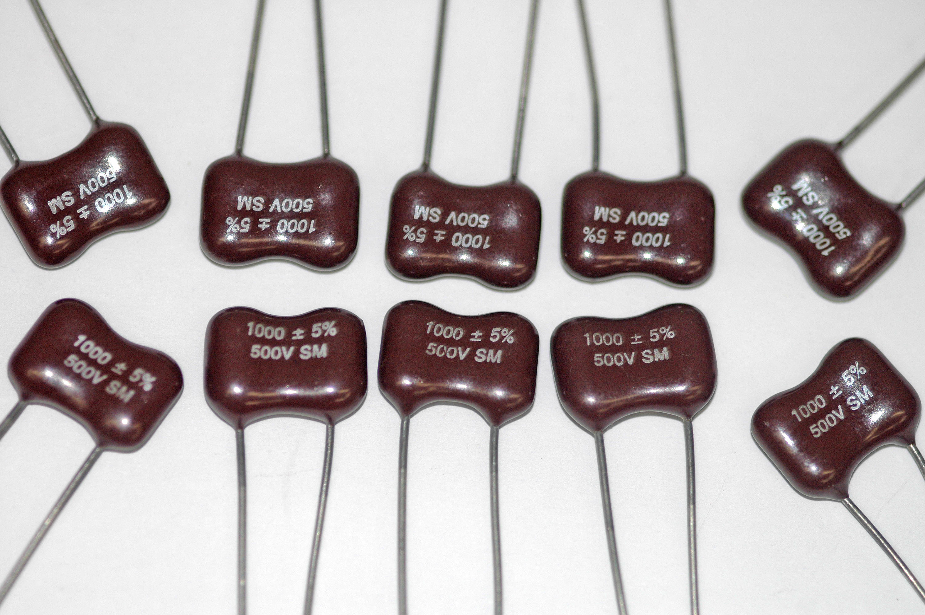
What the reader is buying with all that care is stability, in three separate senses that matter to an RF designer. First, a tight and predictable temperature coefficient: a good silver mica holds a small, positive, well-controlled drift with temperature — on the order of a few tens of parts per million per degree Celsius — where a Class II ceramic of the same value might shift by whole percentage points (the ceramic volume explains why). Second, an extremely low dissipation factor — the fraction of energy lost as heat each cycle, developed at length in the volume on the real, non-ideal capacitor. Silver mica’s DF runs in the neighbourhood of a few parts in ten thousand, giving a very high Q, and it stays low well up into the VHF region. Third, genuine long-term stability: mica does not age, absorb water (once sealed), or shift its value as it sits, and silver micas can be bought to tight tolerances — ±1 % is routine, tighter is available — and trusted to keep them.
That combination is exactly what a tuned circuit wants. Put a silver mica across an inductor to set the frequency of an oscillator, and the oscillator stays put; use one in the coupling or the ladder of a narrow filter, and the passband does not wander; use one in the tank of an RF power amplifier or an antenna matching network, where it must carry real RF current without heating, and its low loss keeps it cool and keeps the match sharp. For decades, if a schematic called for a precise, stable capacitor of a few picofarads to a few nanofarads in a radio circuit, silver mica was the default answer, and in high-end and vintage-restoration work it still is.
The price of admission is the usual one for a specialist. Silver mica is comparatively expensive, because it depends on selected natural mineral and careful hand-ish assembly. It is bulky for its value — the dielectric constant of mica is modest (around 5 to 7), so a silver mica of a given capacitance is far larger than the Class II ceramic that might replace it where stability does not matter. And it is confined to small values: picofarads to a few nanofarads, occasionally into the low tens of nanofarads at the top of the range but rarely beyond. Nobody stores bulk energy in mica. It is a precision instrument, priced and sized like one, and used where precision is worth paying for. Where stability does not matter, a C0G/NP0 ceramic (a Class I ceramic engineered for exactly the same stability virtues, treated in the ceramic volume) now covers much of the same ground more cheaply and in a fraction of the space — but at the very top end of Q and stability, and in the legacy of RF design, mica still holds its corner.
11.3 Glass: mica’s rugged, expensive cousin
Where silver mica reaches its limits — of temperature, of ruggedness, of sheer reliability — the glass capacitor takes over. The dielectric here is exactly what the name says: glass, a specially formulated potash-lead or similar glass drawn into thin ribbon or tube, stacked or wound with metal electrodes, and then fired so that the whole assembly fuses into a single monolithic, hermetically sealed block of glass with the electrodes embedded inside it. There is no organic resin, no trapped air, no seam for moisture to enter — the part is, in effect, a solid lump of glass with a capacitor frozen inside it.
That construction buys extraordinary stability and toughness. A glass capacitor holds a very low, very predictable temperature coefficient over an enormous temperature range — commonly rated to +125 °C and often far beyond, into the +200 °C region and above where organic dielectrics have long since given up. Because it is fused and hermetic it is essentially immune to humidity, and because glass is mechanically hard and chemically inert it shrugs off shock, vibration, and thermal cycling that would crack a lesser part. Its dissipation factor is very low and stable, and its insulation resistance is enormous. In short, a glass capacitor behaves like an idealised, indestructible silver mica.
The consequence is that glass capacitors live almost entirely in aerospace, military, down-hole, and other high-reliability RF work — the places where a capacitor may see wide temperature swings, hard vibration, or a mission where failure is not an option, and where the customer will pay for a part that simply does not drift or die. They share silver mica’s limitations, sharpened: values are small (picofarads to low nanofarads), and the parts are expensive — meaningfully more so than mica — which is precisely why they are reserved for the jobs that justify the cost. A glass capacitor is what a designer specifies when a silver mica would be almost good enough and “almost” is not acceptable.
11.4 Supercapacitors: farads, not microfarads
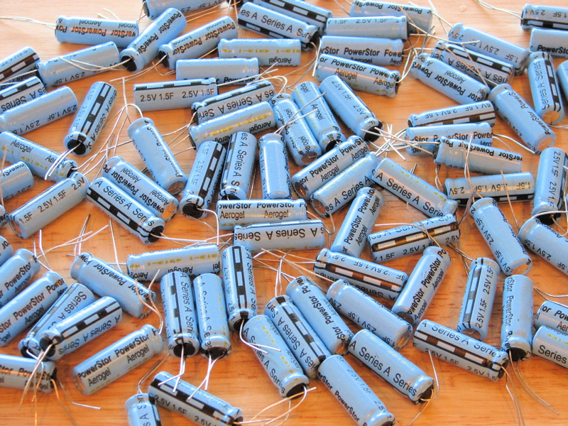
Every capacitor discussed so far in this whole deep dive stores a modest amount of charge in the electric field across a solid dielectric. The supercapacitor — also called an ultracapacitor, or by the technical name electric double-layer capacitor (EDLC) — throws that model out and stores charge by an entirely different physical mechanism, and in doing so it leaves the microfarad behind. Ordinary capacitors are measured in picofarads, nanofarads and microfarads. Supercapacitors are measured in farads, whole farads, tens, hundreds, and now thousands of them, in a single can. A one-farad capacitor is, by the standards of the rest of this deep dive, an almost absurd object; a three-thousand-farad supercapacitor the size of a soda can is routine. Understanding how that is even possible is the whole point of the family.
11.4.1 The double layer, and why the capacitance is enormous
Recall the parallel-plate formula from the foundational volume: capacitance is the permittivity times the plate area, divided by the separation between the plates, C = εA/d. To make capacitance large, a designer wants the biggest possible area A and the smallest possible separation d. The whole history of capacitor technology is a war on those two numbers — thinner dielectrics, more layers, etched and roughened foils to gain area. The supercapacitor wins that war so decisively that it hardly seems to be playing the same game, and it does so by abandoning the solid dielectric entirely.
Inside a supercapacitor there is no dielectric sheet in the ordinary sense. Instead there are two electrodes made of activated carbon — carbon processed into a sponge so riddled with microscopic pores that a single gram of it unfolds to a surface area of one to two thousand square metres. The electrodes sit in a liquid electrolyte full of dissolved positive and negative ions, with a thin porous separator between them that lets ions pass but keeps the electrodes from touching. When a voltage is applied, something subtle and powerful happens at the surface of each electrode: the ions in the electrolyte migrate to the electrode and line up against it, positive ions crowding against the negative electrode and negative ions against the positive one. At each electrode surface a razor-thin sheet of electronic charge on the carbon faces an equally thin sheet of ionic charge in the electrolyte, the two held apart only by the diameter of a solvent molecule — a fraction of a nanometre. This paired sheet of opposite charge is the electric double layer (a structure first described by Helmholtz in the nineteenth century), and it is, in effect, a capacitor whose “plates” are separated not by microns of plastic but by angstroms of nothing much at all.
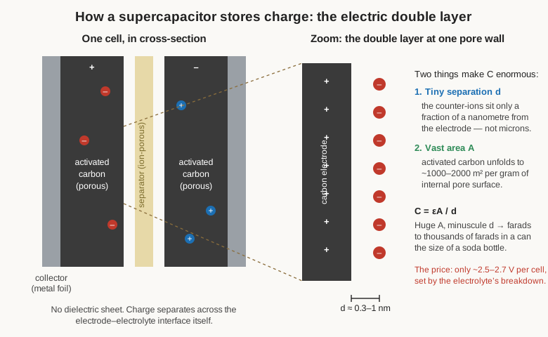
Now put the two multipliers together. The separation d is not the micron of a film capacitor but a fraction of a nanometre — a thousandfold smaller. The area A is not the square centimetres of a wound foil but the thousands of square metres hidden in the carbon’s pores — a millionfold larger. Multiply a thousandfold gain in one factor by a millionfold gain in the other and the capacitance climbs by an almost unbelievable margin. That is why a device the size of an ordinary electrolytic can hold hundreds or thousands of farads: not through any new dielectric, but by storing charge electrostatically across the double layer on an enormous hidden surface at a molecular separation. Some supercapacitors add a second contribution called pseudocapacitance, in which the electrode material (certain metal oxides such as ruthenium or manganese oxide, or conducting polymers) also undergoes fast, shallow, reversible surface reduction–oxidation reactions that store extra charge chemically at the surface — a hybrid of capacitor and battery behaviour that boosts the value further. But the double layer is the heart of it.
11.4.2 The catch: low voltage, and everything that follows
Nothing is free, and the supercapacitor pays for its farads with voltage. The double layer only survives up to the point where the electrolyte itself begins to break down, and for the organic electrolytes used in modern cells that limit sits at roughly 2.5 to 2.7 volts per cell (aqueous-electrolyte cells are limited to about a volt). Push a cell above its rating and the electrolyte decomposes, generating gas, heat, and ruin. Two and a half volts is not much to work with, so real-world supercapacitor modules stack cells in series to reach useful voltages — a 48-volt module is a string of around twenty cells — and that immediately raises a problem the battery world will recognise. Cells in a series string are never perfectly identical, and if they simply share the applied voltage by chance, the weakest cell can find itself over its limit while its neighbours loaf below theirs. Series supercapacitor stacks therefore need voltage balancing — passive bleed resistors across each cell, or active balancing circuits — to keep any one cell from being driven past its rating and cooking itself. A designer who stacks bare cells without balancing them has built a device that will quietly destroy its own weakest member.
Low voltage is only the first of the compromises. A supercapacitor also has notable equivalent series resistance — not disastrous, but far from the milliohms of a good electrolytic — which limits how hard it can be driven and warms it under heavy current. It has high self-discharge and leakage: left charged and disconnected, a supercapacitor sags noticeably over hours and days, where a good film capacitor would hold its charge for a very long time and a battery for months. And for all its farads, its energy density is poor next to a battery — a matter of a few to perhaps ten watt-hours per kilogram, against a hundred and fifty to two hundred and fifty for lithium-ion. The supercapacitor is not a battery replacement for storing energy; measured by energy per kilogram it is roughly an order of magnitude behind.
11.4.3 Energy, power, and the Ragone chart
The clearest way to see where the supercapacitor actually fits is to plot storage technologies on a Ragone chart — energy density on one axis, power density on the other, both logarithmic — because it lays out the fundamental trade in a single picture. A battery stores a great deal of energy but releases it slowly; it lives in the high-energy, low-power corner. An ordinary electrostatic capacitor stores almost no energy but can dump or absorb it in microseconds; it lives in the opposite corner — trivial energy, colossal power. The supercapacitor sits squarely in the gap between them, holding far more energy than any ordinary capacitor while delivering far more power than any battery.
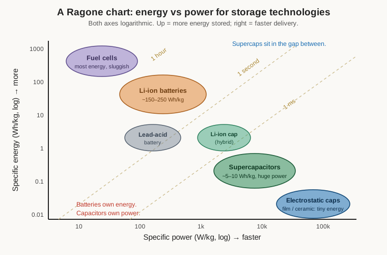
That location on the chart, together with one more virtue, defines every good use of a supercapacitor. The extra virtue is cycle life: because charging a supercapacitor mostly just rearranges ions rather than driving the chemical phase changes that slowly wear out a battery’s electrodes, a supercapacitor can be charged and discharged hundreds of thousands to a million times with little degradation, and it does so happily at temperatures that would harm a battery. So the supercapacitor wins wherever a job needs a lot of power in short bursts, repeated a great many times, and does not need to store energy for long. It is superb for memory backup (holding a clock or volatile RAM alive for minutes to hours through a power interruption), for energy harvesting (soaking up the trickle from a solar cell or vibration harvester and delivering it in usable pulses), for regenerative braking in vehicles and cranes (catching the surge of energy from a stop and handing it back on the next start, a duty cycle that would exhaust a battery), for pulse and peak-power buffering (a camera flash, a car-audio bass transient, a laser, a wireless transmitter’s burst), and for engine-start and cold-crank modules that deliver the brief, brutal current an engine needs while sparing the battery that job.
A middle ground has emerged in the lithium-ion capacitor (LIC), a hybrid that pairs a supercapacitor-style carbon electrode with a lithium-doped battery-style electrode. The result splits the difference: markedly higher energy density and higher working voltage (roughly 2.2 to 3.8 volts per cell) than a plain EDLC, with much lower self-discharge, while keeping a good slice of the supercapacitor’s power and long life. It is the answer when a designer wants most of a supercapacitor’s virtues but cannot stomach its energy density or its leakage. Where the supercapacitor sits versus the aluminium electrolytic it superficially resembles — both are polarised, both are cans, both back up power rails — is a comparison the electrolytics volume takes up in detail; the short version is that the electrolytic wins on voltage, ESR and speed while the supercapacitor wins on sheer stored energy by a wide margin.
11.5 Vacuum and gas-filled high-voltage capacitors
Take the opposite extreme from the supercapacitor. Instead of the largest possible capacitance at the lowest possible voltage, ask for a modest capacitance that will hold off tens of thousands of volts and carry hundreds of amps of radio-frequency current without loss or arc-over. No solid dielectric survives that duty comfortably — under enough voltage every solid eventually punctures, and under enough RF current every lossy dielectric heats and fails. The answer is to use as the dielectric the one insulator that cannot be punctured in the ordinary sense and has essentially no loss: vacuum.
A vacuum capacitor is a set of concentric metal cylinders — nested tubes, one set the fixed electrode and the other the movable or opposing electrode — sealed inside an evacuated glass or ceramic envelope. Vacuum has a relative permittivity of essentially one, so the capacitance per unit area is small and the parts are physically large for their value, but vacuum’s dielectric strength is superb and, crucially, it has no dielectric loss — there is no material to heat — so the capacitor’s Q is extremely high and it can carry enormous RF currents while staying cool. Ratings that would be unthinkable elsewhere are ordinary here: working voltages from a few kilovolts to well over sixty, RF current ratings of tens to hundreds of amps. Some variants replace the vacuum with an inert gas (nitrogen or sulphur hexafluoride) under pressure, trading a little of the vacuum’s perfection for easier manufacture at the highest voltages.
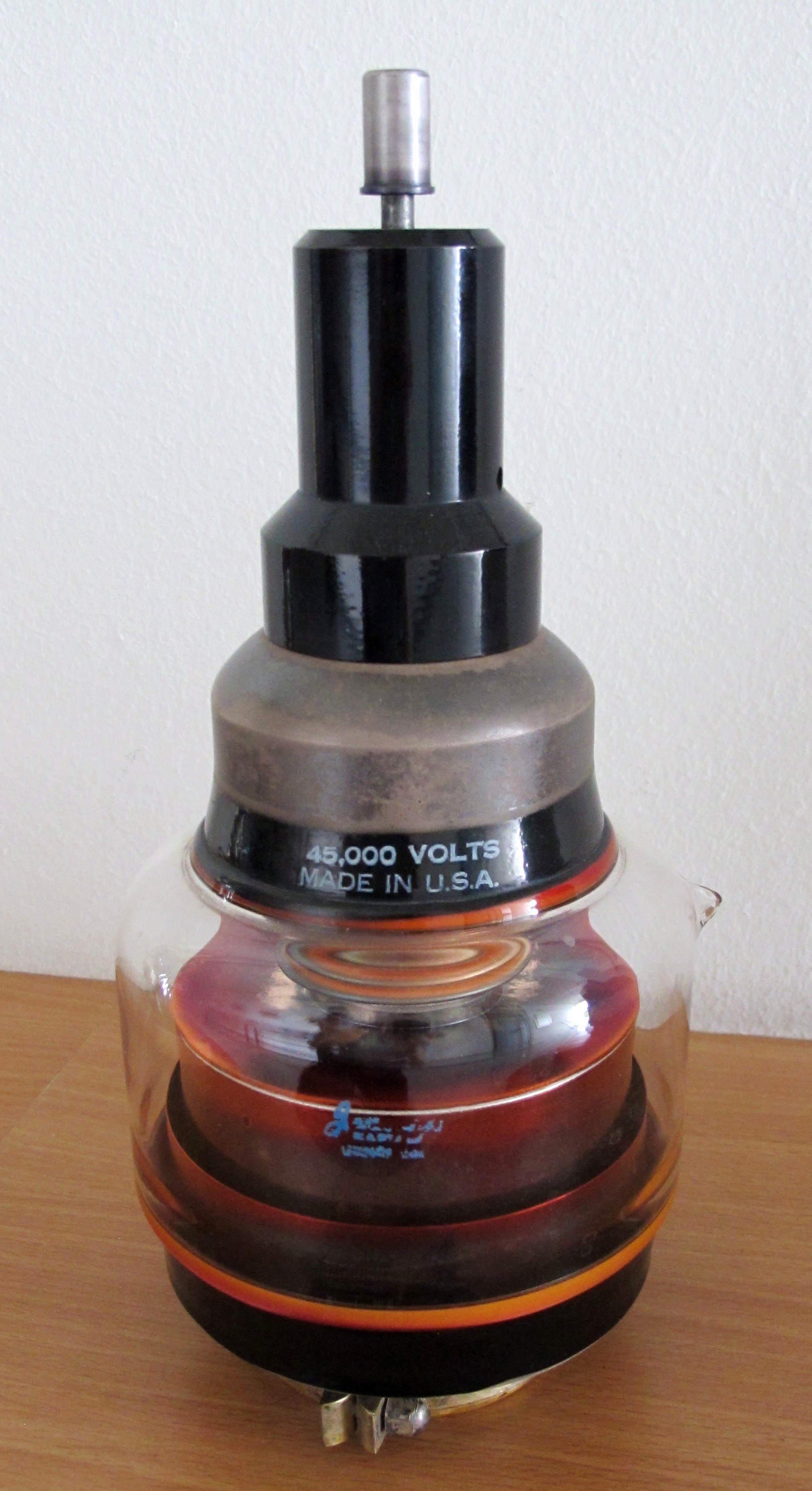
Vacuum capacitors come in fixed and variable forms, and the variable ones hide a lovely piece of mechanical engineering. The two electrode sets must be able to move relative to each other to change the capacitance, yet the envelope must stay sealed against the atmosphere — a moving shaft poking through a vacuum seal would leak. The solution is a metal bellows: one electrode assembly is mounted on a flexible, accordion-pleated metal bellows that forms part of the sealed envelope, and a lead screw outside the vacuum stretches or compresses the bellows, driving the electrodes deeper into or out of mesh while the vacuum seal flexes but never breaks. Turning the knob winds the electrodes in and out like a trombone slide, sealed for life.
These parts are the workhorses of high-power radio frequency. They set the tuning and loading in the antenna tuners and tank circuits of high-power RF transmitters and amateur amplifiers; they form the matching networks of the plasma systems used in semiconductor etching and industrial RF heating, where kilowatts of RF must be matched into a shifting plasma load; they appear in the RF chains of MRI machines and other scientific apparatus. Wherever high voltage and high RF current meet, the vacuum capacitor is usually the only thing that will do the job — and it is priced accordingly, a precision-machined, hand-assembled, evacuated instrument that costs a great deal more than the ceramic doorknob capacitors sometimes used at more modest power.
11.6 Variable capacitors: the tuning knob made physical
Every capacitor family so far has a fixed value. But a radio has to be tuned, an oscillator has to be trimmed onto frequency, a matching network has to be adjusted — and for that a designer needs a capacitor whose value can be changed at will. The variable capacitor is that part, and for most of the twentieth century it was the single most prominent capacitor in any radio, the large air-spaced mechanism directly behind the tuning dial.
The classic air-variable or tuning capacitor works by changing the overlapping area of its plates. A set of stationary metal plates (the stator) is interleaved with a set of plates mounted on a rotating shaft (the rotor); as the shaft turns, the rotor plates swing into or out of mesh with the stator plates, and the overlapping area — and with it the capacitance — rises and falls smoothly. The dielectric between the meshing plates is simply air, chosen for its zero cost, near-zero loss, and the fact that it heals instantly after any flashover. Air’s low permittivity means these capacitors are large for their value, which is exactly why the tuning capacitor is the big shiny mechanical object behind the dial rather than a chip.
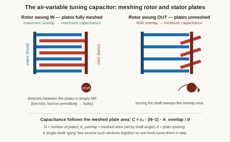
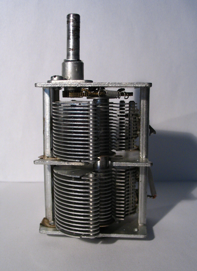
Several practical refinements grew up around this basic mechanism. A single tuning knob often has to adjust two or more circuits at once — the antenna tuned circuit and the local-oscillator tuned circuit of a superheterodyne receiver must track together — so their variable capacitors are built on a common shaft as a “gang” capacitor, two or three (or more) sections turning in step so that one knob tunes them all. Because a small twitch of the fingers must not send the dial flying past the station, a reduction drive (a vernier or planetary gear reducing the knob’s motion, often by five or six to one) gives the fine, smooth control that makes tuning pleasant rather than maddening. And for balanced or push-pull circuits, a split-stator variable puts two stator sections back-to-back around a common rotor, giving two matched, symmetrical variable capacitances at once. A typical AM broadcast-band tuning section runs to a few hundred picofarads at full mesh — 365 pF is the number burned into the memory of anyone who has restored an American radio — down to a handful of picofarads swung fully open.
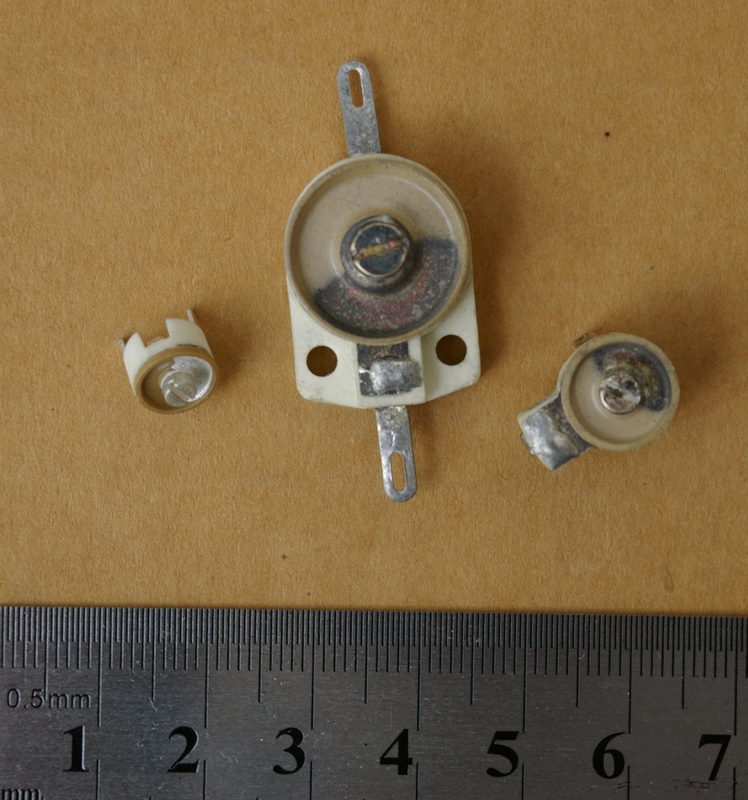
Not every adjustable capacitor needs to be turned every day. Many circuits need a capacitor set once, at the factory or during alignment, and then left alone — the precise value that puts an IF strip exactly on frequency, or trims an oscillator onto its crystal. That is the job of the trimmer (and its larger cousin the padder), a small adjustable capacitor set with a screwdriver. Trimmers come in several constructions, each with its own value range and stability. Ceramic trimmers rotate a shaped metal electrode over a ceramic dielectric disc and cover a few picofarads to a few tens of picofarads cheaply. Compression trimmers — the old “postage-stamp” mica adjusters — use a screw to squeeze a stack of mica sheets, changing the plate spacing and so the value, and were ubiquitous in vintage radios. Air piston trimmers thread a metal piston in and out of a metal tube, varying the overlap; they offer only a small value range (a picofarad or two up to perhaps twenty or thirty) but with excellent stability and Q, which is why they turn up in the most demanding RF alignment. All of them share the trimmer’s defining trait: a small range, set once, meant to nudge a fixed design onto its exact target.
One honourable mention belongs in this section even though it is, strictly, not a capacitor at all. The varactor (or varicap) diode has quietly replaced the mechanical variable capacitor in almost all modern electronic tuning. It is a semiconductor diode run in reverse bias, exploiting the fact that the depletion region of a reverse-biased junction is an insulating gap between two conductors — a capacitor — whose width, and therefore whose capacitance, grows as the reverse voltage is increased. Feed a varactor a control voltage and its capacitance follows, giving voltage-controlled tuning with no moving parts: this is how the phase-locked loops in every modern radio, television and phone tune themselves, and how a voltage-controlled oscillator sweeps. It is worth being clear-eyed about what it is, though. A varactor is a diode, not a true capacitor — it is polarised, nonlinear, leaky, and lossy in ways a real capacitor is not, and it must be biased and isolated with care. It earns its place here only because it does the job the air-variable used to do, electronically; the physics of the two could hardly be more different.
11.7 Feedthrough and EMI-suppression capacitors
Every real capacitor has parasitic series inductance (ESL) — the unavoidable inductance of its own leads and internal current path — and above the part’s self-resonant frequency that inductance, rather than the capacitance, dominates its behaviour, so that a nominally excellent bypass capacitor becomes useless at high enough frequency (the volume on the real capacitor develops self-resonance in full). For most decoupling that is merely a limitation to design around. But for the specific job of stopping high-frequency noise from leaking through the wall of a shielded enclosure, it is fatal — the noise the capacitor is meant to shunt away is precisely the high-frequency energy at which an ordinary capacitor’s inductance has already given up.
The feedthrough capacitor is built specifically to have almost no series inductance, and it does so with a clever three-terminal, coaxial geometry. The conductor whose noise is to be filtered passes straight through the middle of the capacitor — through the axis of a ceramic tube — and the outer surface of that tube is metallised and bonded directly to the metal bulkhead or shield wall it penetrates. The capacitance is formed between the through-conductor and the grounded outer shell, all the way around, so the high-frequency noise on the conductor is shunted to the shield through a short, symmetric, coaxial path with essentially no loop area and therefore essentially no inductance. Because it is a three-terminal device — signal in, signal out, and a ground that is the shield — rather than a two-terminal part hung off to one side, there is no lead stub to resonate, and the capacitor keeps filtering effectively far higher in frequency than any ordinary bypass could.
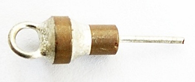
Feedthrough capacitors are the standard tool for taking a wire cleanly through the wall of a screened room, a die-cast RF enclosure, or a filter connector without letting it carry interference across the boundary — filtered connectors are, in effect, rows of tiny feedthrough capacitors, one per pin. They are close kin to the mains X- and Y-class safety-and-suppression capacitors discussed in the film volume, and they lean on exactly the low-ESL thinking developed in the volume on the real capacitor; the family is included here as the specialty answer to the question of getting a conductor through a shield without dragging its noise along.
11.8 Motor-run and motor-start capacitors
A single-phase alternating-current supply has a problem when asked to start a motor: a single sinusoidal current, on its own, produces a magnetic field that pulses back and forth in place rather than rotating, and a pulsing field cannot start a motor turning. The trick a single-phase induction motor uses to solve this is to create a second, phase-shifted current in an auxiliary winding, so that the two windings together produce a field that sweeps around — a rotating field — and drags the rotor into motion. The component that provides that phase shift is a capacitor, and two quite different capacitors do the two halves of the job. Confusing them, or substituting one for the other, is a classic and destructive mistake.
The start capacitor provides the big phase shift needed to wrench a stationary motor into motion. It must be a high capacitance — commonly tens to a few hundred microfarads — to push enough current through the auxiliary winding for good starting torque, and it is needed only for the second or two it takes the motor to come up to speed, after which a centrifugal switch or relay disconnects it. Because it works only intermittently, in brief bursts, it can be built cheaply and compactly as a nonpolar aluminium electrolytic capacitor — the same wet-electrolytic technology covered in the electrolytics volume, arranged in a nonpolar back-to-back form so it can handle AC for those brief starting moments. It absolutely cannot tolerate continuous AC duty; that is not what it is for.
The run capacitor, by contrast, stays in the circuit the whole time the motor runs, continuously trimming the phase of the auxiliary winding to improve efficiency, power factor and smoothness. Because it is energised continuously on the AC line, it must be a genuinely AC-rated, continuous-duty part with very low loss, and it is therefore built as an oil-filled metallised-polypropylene film capacitor (the film volume covers the dielectric) — a smaller value than the start cap, commonly a few to a few tens of microfarads, but rated to sit across hundreds of volts of AC indefinitely without heating.
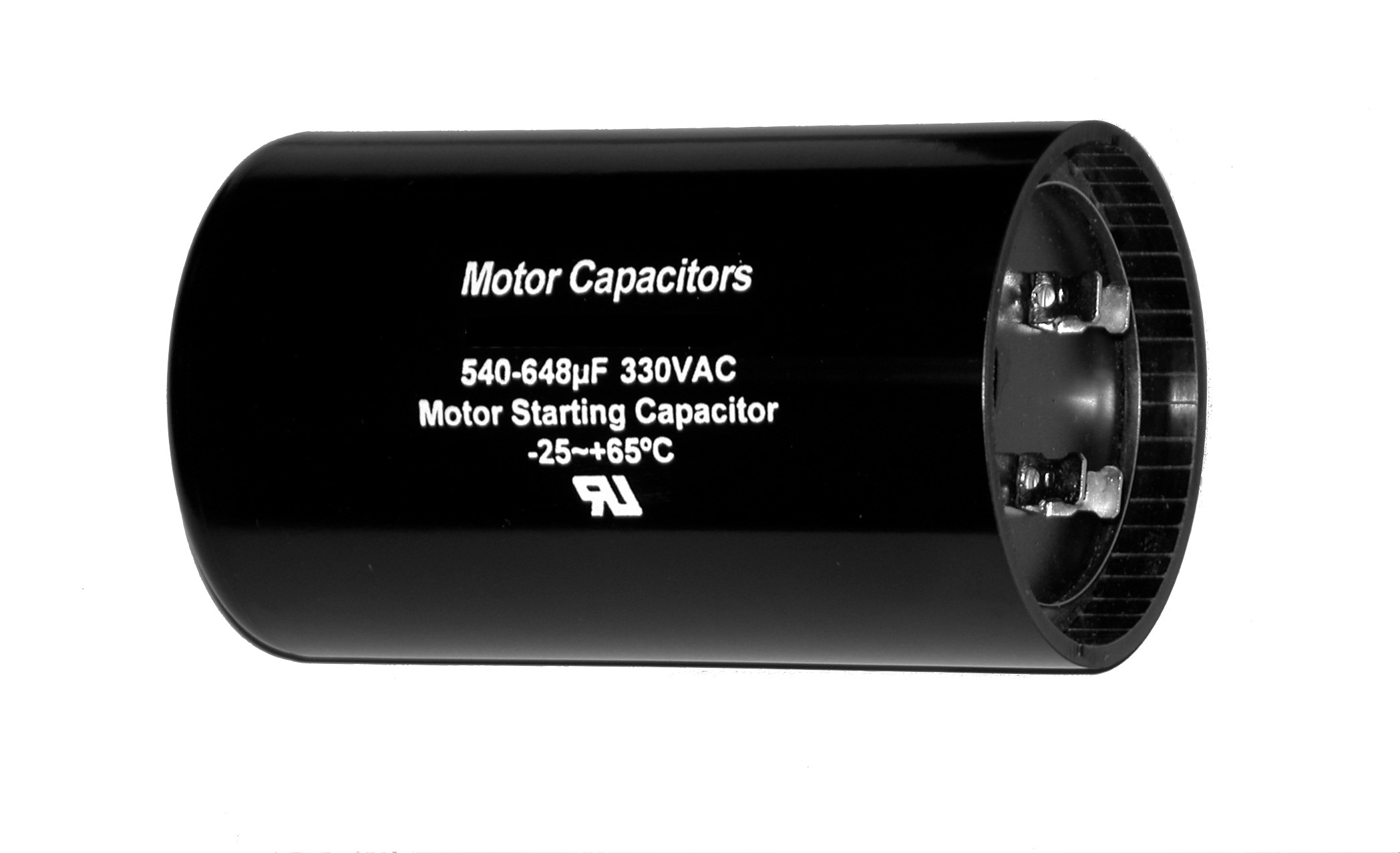
The reason the distinction matters, and the reason the two must never be swapped, follows directly from how each is built. Fit a film run capacitor where a start capacitor belongs and it will provide far too little capacitance to start the motor, which will hum, stall, and overheat without turning. Fit an electrolytic start capacitor where a run capacitor belongs — leaving that intermittent-duty electrolytic energised continuously on the AC line — and it will rapidly overheat, vent, and fail, because it was never built to sit across the mains for more than a couple of seconds at a time. The values differ, the duty ratings differ, and the underlying dielectric technologies differ; the two parts merely happen to share a job title. (The detailed behaviour of the wet-electrolytic construction inside a start capacitor belongs to the electrolytics volume; here the point is only the division of labour between the two.)
11.9 Integrated and on-chip capacitors: the small end of the scale
At the very opposite end of the size scale from a vacuum capacitor or a supercapacitor sit the capacitors built inside integrated circuits, too small to see and never sold as separate parts, yet made by the billion. They matter to this survey because they show how far the same physics stretches, down to structures measured in nanometres.
The commonest on-die capacitor is the MIM — metal–insulator–metal — capacitor, which is exactly what its name says: two metal plates laid down in the chip’s upper interconnect layers with a thin deposited dielectric (silicon dioxide, silicon nitride, or a high-permittivity oxide such as aluminium, hafnium or tantalum oxide) between them. It is a parallel-plate capacitor in the most literal sense, fabricated a few microns above the transistors, and it provides the stable, linear, well-controlled capacitance that on-chip analogue and RF circuits need — the sampling capacitors of an analogue-to-digital converter, the compensation of an amplifier, local decoupling right at the point of use. The MOS capacitor uses the transistor’s own gate-oxide sandwich — gate metal over thin oxide over silicon — as a capacitor, cheap and dense but more voltage-dependent, and widely used for on-die decoupling where linearity does not matter. And to reach the highest capacitance in the least chip area, trench or silicon capacitors etch deep, narrow trenches down into the silicon and line them, multiplying the plate area in the third dimension exactly as DRAM storage cells do; discrete silicon-capacitor products built this way pack surprising value and excellent stability into a bare-die part small enough to sit under another chip. These integrated capacitors are the reason a modern processor can be decoupled at frequencies no discrete part could follow: the capacitor is right there on the die, its inductance almost nil because there are no leads at all.
11.10 The zoo, organized
Stand back from the menagerie and the logic of it resolves into a single sentence per specialist — each is the part that owns one job. Silver mica owns the small, stable, low-loss capacitor for RF oscillators, filters and tuned circuits, where drift is the enemy and cost is acceptable. Glass owns the same territory pushed to military and aerospace extremes of temperature and ruggedness. Supercapacitors own the middle of the Ragone chart — far more energy than any capacitor, far more power than any battery, a million cycles of it — for memory backup, energy harvesting, regenerative braking and pulse power, at the price of low voltage and poor energy density. Vacuum and gas-filled capacitors own high-power RF, holding off tens of kilovolts and carrying hundreds of amps where every solid dielectric would arc or melt. Variable capacitors own adjustment: the air-gang for tuning a radio, the trimmer for aligning it once, the varactor for doing both electronically (while quietly admitting it is really a diode). Feedthrough capacitors own the specific job of getting a conductor through a shield without its noise, by having almost no inductance to spoil the filtering. Motor-run and motor-start capacitors own the phase-shift that lets a single-phase motor turn — one continuous, one intermittent, and never interchangeable. And the integrated capacitors own the smallest end of the scale, decoupling and shaping signals inside the silicon itself.
None of these would make a good general-purpose capacitor, and that is precisely the point. The four big families earn their dominance by being good enough at everything; the specialists earn their existence by being the best, or the only, choice at one thing. Choosing among them — knowing when the job genuinely calls for a specialist and when a mainstream part will do — is the subject of the selection volume, which turns this whole deep dive’s worth of families into a single working decision.
Related volumes: the foundational volume (charge, capacitance, C = εA/d and stored energy — the physics every family here rests on); the film volume (the metallised-polypropylene dielectric of motor-run and snubber capacitors, and the X/Y suppression caps kin to the feedthrough); the aluminium-electrolytic volume (the wet-electrolytic construction inside a motor-start capacitor, and the supercapacitor-versus-electrolytic comparison in full); the ceramic volume (Class I C0G/NP0 as the modern rival to silver mica, and the ceramic dielectric of trimmers and feedthroughs); the real-capacitor volume (ESR, ESL and self-resonance — why the feedthrough’s low inductance matters); the markings volume (decoding the coloured-dot code on vintage postage-stamp micas); and the selection volume (when a job genuinely calls for one of these specialists).
Comments (0)