Capacitors · Volume 14
Reference: Glossary, Tables, and Formulas
14.1 How to use this reference
This closing volume is a lookup desk, not an essay. Where the family volumes argue and explain, this one simply lists — the terms, the numbers, the codes, the equations, and the standards named across the whole dive — so that a definition, a dielectric constant, an EIA code, or a formula can be found in seconds without re-reading a chapter. Every figure here is drawn to match the volume that treats it in full; where a term “gets its real treatment in the ceramic volume” or “the electrolytic volume,” the cross-reference points there rather than repeating the argument. Nothing in this volume is new physics. It is the index to the physics already laid out, arranged for the bench.
Glossary
The definitions below are terse by design; the parenthetical pointer names the volume where each idea is developed properly.
Aging — The slow, logarithmic loss of capacitance in Class II/III ferroelectric ceramics as their crystal domains relax after firing, a roughly constant percentage per decade-hour (about 1–2 % for X7R, 4–6 % for Z5U). Reversible by heating above the Curie point. Class I and film do not age. (ceramic volume)
Anode — The positive electrode of a polarized capacitor; in electrolytics and tantalums it is the metal (aluminum, tantalum) on which the oxide dielectric is grown. (electrolytic, tantalum volumes)
Anodizing (forming) — Growing the oxide dielectric electrochemically on the anode by applying a DC voltage in an electrolyte bath. Oxide thickness is set by the forming voltage — roughly 1.4 nm/V for aluminum oxide, 1.7 nm/V for tantalum pentoxide. (manufacturing volume)
Anti-resonance — An upward impedance spike that appears when a larger (inductive) capacitor is paralleled with a smaller (still-capacitive) one and they form a parallel LC tank. Tamed by keeping value ratios modest and leaning on low-ESR parts. (real-capacitor volume)
Bipolar (non-polar) electrolytic — An electrolytic built with two anode foils back-to-back so it tolerates either polarity, used for loudspeaker crossovers and AC coupling; roughly half the capacitance per volume of the polarized version. (electrolytic volume)
Bleeder resistor — A resistor deliberately wired across a large capacitor so its stored charge drains to a safe level within seconds after power-down. (fundamentals volume)
Breakdown voltage — The voltage at which the dielectric fails and conducts, often destructively; a film or ceramic punches through, an electrolytic vents, a tantalum may ignite. Sits above the surge and working voltages. (real-capacitor volume)
Bulk (reservoir) capacitor — A large capacitor that stores energy to hold a supply rail up between charging peaks; the classic aluminum-electrolytic job. (selection, electrolytic volumes)
Bypass capacitor — A capacitor that shunts high-frequency noise on a rail to ground. Closely related to decoupling and often used interchangeably. (selection volume)
C0G / NP0 — The flagship Class I ceramic: 0 ± 30 ppm/°C temperature coefficient, negligible DC-bias loss, no aging, dissipation factor below ~0.1 %. NP0 (“negative-positive-zero”) is the older name; C0G is the systematic EIA code for the same zero-drift characteristic. (ceramic volume)
Capacitance — The charge a capacitor holds per volt applied, C = Q/V, measured in farads. Set by geometry and dielectric: C = ε₀·εᵣ·A/d. (fundamentals volume)
Cathode — The negative electrode. In an electrolytic the true cathode is the liquid or solid electrolyte that contacts the oxide over its whole area; the “cathode foil” is only a current collector. (electrolytic volume)
Class I / Class II / Class III (ceramic) — The EIA sorting of ceramic dielectrics. Class I (paraelectric, C0G and the P/N temperature-compensating codes) is stable and low-permittivity; Class II (ferroelectric barium titanate, X7R/X5R) is high-permittivity but drifts, ages, and sags under bias; Class III (Y5V/Z5U) pushes permittivity higher still for the worst stability. (ceramic volume)
Clearing — See self-healing.
Condenser — The obsolete word for a capacitor, still found on vintage schematics (“condenser microphone,” the ignition “condenser”). Means exactly the same thing. (fundamentals, history volumes)
Coupling capacitor — A capacitor in series with a signal that passes the AC while blocking the DC offset between two stages. The leaky coupling capacitor is the classic vintage-amplifier killer. (paper volume)
Curie point (Curie temperature) — The transition temperature (around 120–130 °C for barium titanate) above which a ferroelectric ceramic loses its spontaneous polarization; heating past it de-ages a Class II part. (ceramic volume)
CV product — Capacitance multiplied by rated voltage, the figure of merit for how much a given electrolytic or tantalum pellet can do; specific charge is quoted in µF·V per gram. (tantalum volume)
DC bias (capacitance loss) — The collapse of Class II/III ceramic capacitance as a steady DC field saturates the ferroelectric domains; a “10 µF” X5R near rated voltage may deliver 3–4 µF. Worse for smaller cases, higher permittivity, and voltages near the rating. (ceramic volume)
Decoupling capacitor — A small local reservoir beside a chip’s power pin that supplies fast current transients and keeps the rail steady; the single most common capacitor role. (selection volume)
Derating — Operating a capacitor well below its rated voltage (and ripple, temperature) to buy reliability and, for Class II ceramic, to keep capacitance. Tantalum doctrine is 50 % of rated, tighter on stiff rails. (real-capacitor, tantalum volumes)
Dielectric — The insulator between the plates. Its permittivity, loss, breakdown strength, and stability define the whole family a capacitor belongs to. (fundamentals volume)
Dielectric absorption (DA, soakage) — The “returning voltage” that reappears on a capacitor’s terminals after it is charged, briefly shorted, and left open; the time-domain fingerprint of slow polarization. Quantified as DA (%) = 100 × Vᵣ/V₀. Ruins sample-and-hold and precision integrators. (real-capacitor volume)
Dielectric constant — See relative permittivity.
Dissipation factor (DF, tan δ) — The fraction of energy lost per cycle relative to energy stored, equal to ESR/Xc = tan δ. The reciprocal of Q. Quoted with a test frequency. (real-capacitor volume)
EDLC (supercapacitor) — Electric double-layer capacitor: stores charge in the nanometre-thin double layer at a high-surface-area electrode/electrolyte interface, reaching farads to thousands of farads at ~2.5–3.0 V per cell. Bridges capacitor and battery. (specialty volume)
EIA — The Electronic Industries Alliance (successor to RMA/RETMA), whose standards (notably RS-198) define the ceramic class codes, tolerance letters, and value codes used throughout. (markings volume)
Electrolyte — The conductive liquid or solid that serves as the true cathode of an electrolytic or tantalum, penetrating the oxide’s roughened surface. Its drying-out is the wet electrolytic’s wear-out mechanism. (electrolytic volume)
Equivalent circuit — The four-element model of a real capacitor: ideal C in series with ESR and ESL, shunted by insulation resistance (leakage). (real-capacitor volume)
ESL (equivalent series inductance) — The lumped inductance of the electrodes, terminations, leads, and mounting loop; it makes a capacitor behave as an inductor above its self-resonant frequency. Smaller packages have less ESL. (real-capacitor volume)
ESR (equivalent series resistance) — The lumped series resistance — metal plus dielectric loss — that turns ripple current into heat (P = I²·ESR) and sets the floor of a decoupling impedance. Frequency- and temperature-dependent; high and cold-sensitive in wet electrolytics. (real-capacitor volume)
E-series — The preferred-number sequences (E3, E6, E12, E24, E48, E96) that set the standard capacitance and resistance values, spaced logarithmically to match tolerance bands. (this volume, below)
Farad (F) — The SI unit of capacitance, one coulomb per volt. A preposterously large unit; practical values live in µF, nF, and pF. Named for Michael Faraday. (fundamentals volume)
Feedthrough capacitor — A three-terminal capacitor mounted through a shield wall so a signal or supply line passes through it while high-frequency noise is shunted to the wall; near-ideal filtering with minimal ESL. (specialty volume)
Ferroelectric — A material (barium titanate) with domains of spontaneous polarization that can be reoriented by a field, giving enormous permittivity at the price of temperature, voltage, and time dependence, plus piezoelectricity. Underlies all Class II/III ceramics. (ceramic volume)
Field crystallization — The slow, field-driven conversion of amorphous Ta₂O₅ into a poorly-insulating crystalline form at a weak spot; the seed of the tantalum ignition failure. (tantalum volume)
Film/foil — Film construction in which the electrode is a separate metal foil rather than a deposited coating; rugged and high-current, but larger and non-self-healing. (film volume)
Forming — See anodizing. Also the deliberate re-growth of oxide when reforming old electrolytics.
Impedance (Z) — The total AC opposition of a real capacitor: |Z| = √(ESR² + (Xc − XL)²). Falls in the capacitive region, bottoms at ESR at the self-resonant frequency, then rises inductively. (real-capacitor volume)
Insulation resistance — The resistance across the dielectric (the leakage path), often quoted as an RC product in MΩ·µF — which, read as a number, is the self-discharge time constant in seconds. (real-capacitor volume)
Leakage current — The small DC current that crosses a real dielectric under applied voltage; low in film and C0G, high in electrolytics and tantalums (spec’d as a current or K·C·V). (real-capacitor volume)
Loss angle (δ) — The angle by which a real capacitor’s impedance vector tips off the pure-reactance axis; tan δ = DF. (real-capacitor volume)
Metallized film — Film construction in which the electrode is a 20–50 nm metal layer vacuum-deposited onto the plastic; small, cheap, and self-healing, but limited in current. (film volume)
MLCC — Multilayer ceramic (chip) capacitor: dozens to hundreds of thin ceramic layers interleaved with printed electrodes and co-fired into a monolithic block. The most-manufactured component in history. (ceramic, manufacturing volumes)
Motor-run / motor-start capacitor — AC-rated capacitors (run: continuous, usually polypropylene; start: intermittent, often non-polar electrolytic) used to phase-shift current in single-phase motors. (specialty, film volumes)
Niobium oxide capacitor — An electrolytic built on a niobium-monoxide (NbO) anode with an Nb₂O₅ dielectric (εᵣ ≈ 41); inherently fire-resistant, cheaper metal, but lower voltage and higher leakage than tantalum. (tantalum volume)
Non-polarized — Having no required orientation; ceramic, film, mica, and glass parts may be fitted either way round. (fundamentals volume)
Oxide dielectric — A dielectric grown as a metal-oxide skin (Al₂O₃, Ta₂O₅, Nb₂O₅) directly on the anode, only nanometres thick — the reason electrolytics reach such capacitance density. (electrolytic, tantalum volumes)
Paraelectric — A dielectric (the titanates of Class I) with no ferroelectric domains, hence low permittivity but excellent stability. (ceramic volume)
Permittivity (ε) — A material’s ability to permit an electric field to store charge, ε = ε₀·εᵣ. Properly complex, ε = ε′ − jε″, where ε″ is the loss part. (fundamentals, real-capacitor volumes)
Permittivity of free space (ε₀) — The vacuum baseline, ≈ 8.85 × 10⁻¹² F/m. (fundamentals volume)
Piezoelectricity (“singing capacitor”) — The mechanical strain a ferroelectric Class II ceramic develops under applied voltage; driven by SMPS ripple it flexes the board audibly, and works in reverse as a microphonic. Absent in C0G. (ceramic volume)
Polarization — The slight internal charge separation a dielectric develops in a field (electronic, ionic, dipolar, interfacial), which is what raises capacitance; its lag with frequency causes loss and dielectric absorption. (real-capacitor volume)
Polarity — The required orientation of an electrolytic or tantalum. Aluminum marks the negative lead; tantalum marks the positive — opposite conventions. Longer lead is positive on fresh radial parts. (fundamentals, markings volumes)
Pseudocapacitance — Charge storage via fast, reversible surface redox reactions (as in some supercapacitor electrodes), supplementing pure double-layer capacitance. (specialty volume)
Q (quality factor) — The reciprocal of DF, Q = Xc/ESR = 1/tan δ. High Q means low loss; a C0G or silver mica can reach thousands. (real-capacitor volume)
Reactance, capacitive (Xc) — The idealized frequency-dependent opposition of a capacitor, Xc = 1/(2πfC); falls as frequency rises. (fundamentals volume)
Reforming — Slowly re-growing the oxide of a long-stored electrolytic by ramping voltage with the current limited, healing storage degradation. Does not cure genuine dry-out. (electrolytic volume)
Reservoir capacitor — See bulk capacitor.
Ripple current — The RMS AC current a capacitor carries in a power supply; a hard published rating because I²·ESR heat governs electrolytic life. Rises with frequency as ESR falls. (real-capacitor, electrolytic volumes)
RC time constant (τ) — τ = R·C, the natural clock of charge/discharge: 63 % of the way in one τ, essentially complete after five. (fundamentals volume)
Schoopage (end spray) — The molten-metal spray that contacts every turn of an extended-foil wound element at once, slashing ESR and ESL; named for Max Schoop. (manufacturing volume)
Self-healing (clearing) — In metallized film (and MnO₂ tantalum, mildly), the local vaporization of the thin electrode around a breakdown, isolating the fault and letting the part survive with a tiny capacitance loss. Makes safety capacitors fail open. (film volume)
Self-resonant frequency (SRF) — The frequency where Xc = XL and impedance bottoms out at ESR: SRF = 1/(2π√(L·C)). Above it the part is inductive. (real-capacitor volume)
Sintering — Fusing pressed powder grains at high temperature without fully melting them, producing the porous tantalum sponge (or densifying an MLCC’s ceramic). (manufacturing volume)
Snubber — A capacitor (usually film/foil polypropylene) placed across a switching device to absorb voltage spikes and damp ringing, chosen for high dV/dt capability. (selection, film volumes)
Surge voltage — A transient voltage limit above the working voltage that a part may tolerate briefly (electrolytics rate it ~10–15 % over working). (real-capacitor volume)
Tan δ — See dissipation factor.
Temperature coefficient (tempco) — How much capacitance drifts with temperature, in ppm/°C for stable dielectrics or as a ±% band for Class II. Distinct from the survival temperature rating. (real-capacitor, ceramic volumes)
Tolerance — The allowed spread of the actual value from the marked value, coded by a letter (J = ±5 %, K = ±10 %, M = ±20 %, Z = +80/−20 %, and absolute-pF codes below 10 pF). (markings volume)
Varactor (varicap) — A diode operated in reverse bias as a voltage-controlled variable capacitor, used for electronic tuning. (specialty volume)
Working voltage (rated voltage) — The maximum continuous DC a capacitor is designed to sustain; a ceiling, not an operating point. (real-capacitor volume)
X capacitor / Y capacitor (safety) — Mains-rated film capacitors under IEC 60384-14. Class X sits line-to-line (must not catch fire; X1/X2/X3 by surge); Class Y bridges line-to-ground (must fail open; Y1/Y2 by surge and insulation). Never interchangeable with ordinary parts. (film volume)
14.2 Master dielectric and family comparison
One table, every major family, for side-by-side comparison. Numbers are representative ballparks consistent with the family volumes and manufacturer literature; specific parts vary. εᵣ is the dielectric constant; “DA” is dielectric absorption; ESR and cost are relative orders of magnitude. Value and voltage ranges are the practical commercial spread, not absolute limits. The table scrolls sideways on narrow screens.
Table 1 — Master dielectric and family comparison
| Family | Dielectric | εᵣ | Typical value range | Voltage range | Tolerance | Tempco / stability | ESR | Polarity | DA | Rel. cost | Signature uses |
|---|---|---|---|---|---|---|---|---|---|---|---|
| C0G / NP0 ceramic | paraelectric titanate | ~6–90 | 0.5 pF – 0.1 µF | 16 V – 5 kV+ | ±0.1 pF … ±5 % (B–J) | 0 ± 30 ppm/°C | very low (mΩ) | none | < 0.1 % | low–med | timing, RF resonators, precision analog |
| X7R ceramic | ferroelectric BaTiO₃ | ~2000–4000 | 100 pF – 100 µF | 6.3 V – 1 kV | ±10–20 % (K/M) | ±15 %, −55/+125 °C | low (mΩ) | none | ~1–2.5 % | low | general decoupling / bypass |
| Y5V ceramic (Class III) | high-εᵣ BaTiO₃ | up to ~15 000 | 1 nF – 100 µF | 6.3 – 50 V | +80/−20 % (Z) | +22/−82 %, −30/+85 °C | low (mΩ) | none | high | lowest | non-critical bulk bypass |
| Polyester / PET film | plastic film | ~3.3 | 1 nF – 10 µF | 50 V – 1 kV | ±5–10 % (J/K) | ~±5 %, mild + | low (mΩ–0.1 Ω) | none | 0.2–0.5 % | low–med | general coupling, bypass, timing |
| Polypropylene / PP film | plastic film | ~2.2 | 100 pF – ~10 µF | 100 V – 2 kV+ | ±1–5 % | small, ~−200 ppm/°C | very low | none | 0.01–0.1 % | med | snubbers, AC, pulse, resonant, audio |
| Polystyrene film | plastic film | ~2.5 | 10 pF – 0.1 µF | 30 – 630 V | ±1–2 % | −125 ppm/°C | low | none | < 0.05 % | med–high | precision timing/filters (obsolescent) |
| PPS film | plastic film | ~3.0 | 100 pF – ~1 µF | 16 – 100 V | ±1.5–5 % | flat, small | low | none | ~0.05–0.1 % | med | SMD precision, temp-stable |
| Silver mica | natural mica | ~5–7 | 1 pF – 10 nF | 100 V – kV | ±1 pF … ±5 % | +20 to +100 ppm/°C | very low (high Q) | none | < 0.1 % | high | precision & HV RF, filters |
| Glass | fused/borosilicate glass | ~5–10 | 0.1 pF – ~10 nF | 100 – 500 V+ | ±1–5 % | ~+140 ppm/°C, very stable | very low (high Q) | none | very low | high | extreme-reliability RF, high-temp, mil/space |
| Aluminum electrolytic (wet) | grown Al₂O₃ | ~8–10 | 0.1 µF – 1 F+ | 6.3 – 550 V | ±20 % (−10/+50 older) | value loose; ESR temp-sensitive | high (0.01–several Ω) | polarized (stripe = −) | ~10 %+ | lowest per µF | bulk storage, smoothing, reservoir |
| Aluminum polymer | grown Al₂O₃ | ~8–10 | 1 – ~2200 µF | 2.5 – 100 V | ±20 % | stable; low temp drift | very low (mΩ) | polarized | high | med–high | low-ESR bulk, VRM, post-Plague boards |
| Tantalum (MnO₂ solid) | grown Ta₂O₅ | ~27 | 0.1 – ~1000 µF | 2.5 – 50 V (derate 50 %) | ±10–20 % | flat vs V and T | moderate (0.1–few Ω) | polarized (bar = +) | few % | high | dense stable bulk (ignition risk) |
| Tantalum (polymer) | grown Ta₂O₅ | ~27 | 1 – ~1000 µF | 2.5 – 25 V | ±20 % | flat vs V and T | low (mΩ) | polarized (bar = +) | few % | high | low-ESR point-of-load bulk, benign failure |
| Wet tantalum | grown Ta₂O₅ | ~27 | 1 – ~2200 µF | to ~125 V | ±20 % | very stable, sealed | low–moderate | polarized (strict) | few % | highest | mil / aerospace / implantable high-rel |
| Niobium oxide | grown Nb₂O₅ | ~41 | ~1 – 470 µF | 2.5 – 10 V | ±20 % | flat vs V and T | moderate | polarized | high | med | fire-safe low-voltage bulk |
| Supercapacitor (EDLC) | electric double layer | n/a | 0.01 – 3000 F+ | 2.5 – 3.0 V / cell | −20/+80 % | large drift; high self-discharge | mΩ – several Ω | polarized (marked) | very high | high per part | memory backup, energy buffer, ride-through |
| Paper (vintage) | wax/oil-impregnated kraft | ~2–4 | 100 pF – several µF | 100 V – 1 kV+ | ±10–20 % | poor, drifts | moderate | none | moderate | obsolete | historical coupling/bypass — replace on sight |
The single most useful pattern in the table: capacitance density and stability trade against each other. The rows near the top (C0G, film, mica, glass) hold their value and cost board space; the rows near the bottom (high-K ceramic, electrolytic, tantalum, supercapacitor) pack in the microfarads and pay in DC-bias loss, drift, leakage, polarity, or a limited life.
14.3 EIA code tables
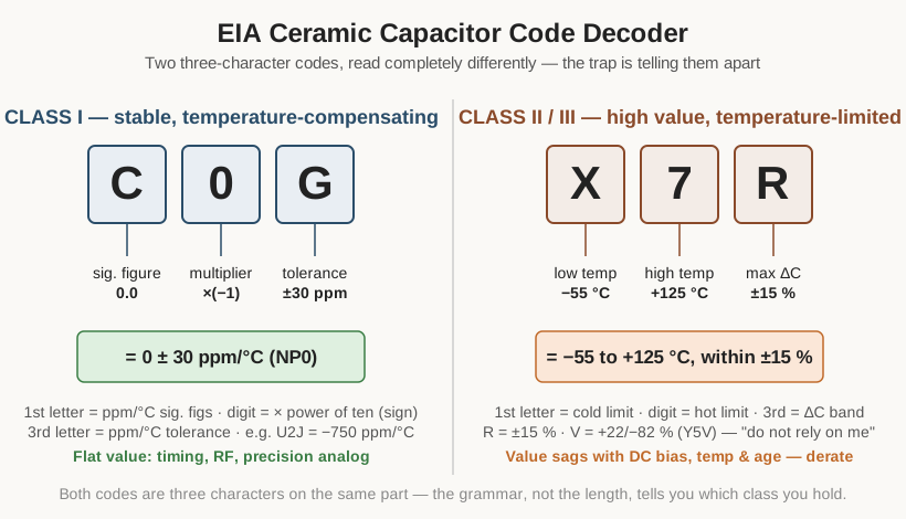
14.3.1 Class I temperature-coefficient code (the C0G family)
A Class I code is three characters: a significant-figure letter for the temperature coefficient in ppm/°C, a multiplier digit (which also carries the sign), and a tolerance letter in ppm/°C. Work C0G through it — C = 0.0, 0 = ×(−1), G = ±30 — and the answer is 0 ppm/°C held to ±30. (ceramic volume)
Table 2 — Class I temperature-coefficient code (the C0G family)
| 1st char — significant figures (ppm/°C) | 2nd char — multiplier | 3rd char — tolerance (ppm/°C) |
|---|---|---|
| C = 0.0 · B = 0.3 · L = 0.8 · A = 0.9 | 0 = ×(−1) · 1 = ×(−10) | G = ±30 · H = ±60 |
| M = 1.0 · P = 1.5 · R = 2.2 · S = 3.3 | 2 = ×(−100) · 3 = ×(−1000) | J = ±120 · K = ±250 |
| T = 4.7 · V = 5.6 · U = 7.5 | 5 = ×(+1) · 6 = ×(+10) | L = ±500 · M = ±1000 |
| 7 = ×(+100) · 8 = ×(+1000) | N = ±2500 |
The common temperature-compensating designations (the “P/N” numbers used to cancel drift in LC circuits) and their EIA codes:
Table 3 — The common temperature-compensating designations (the "P/N" numbers used to cancel drift in LC circuits) and their EIA codes
| Industrial name | Tempco (ppm/°C) | Tolerance | EIA code |
|---|---|---|---|
| P100 | +100 | ±30 | M7G |
| C0G / NP0 | 0 | ±30 | C0G |
| N075 | −75 | ±30 | U1G |
| N150 | −150 | ±60 | P2H |
| N220 | −220 | ±60 | R2H |
| N330 | −330 | ±60 | S2H |
| N470 | −470 | ±60 | T2H |
| N750 | −750 | ±120 | U2J |
| N1500 | −1500 | ±250 | P3K |
14.3.2 Class II / III code (X7R, Y5V, and kin)
A Class II/III code describes a box, not a slope: a low-temperature limit, a high-temperature limit, and the maximum capacitance change across that range (measured at low signal, no DC bias). It is read completely differently from the Class I triplet — a trap, since both are three characters on ceramic. So X7R = −55 °C to +125 °C, within ±15 %. (ceramic volume)
Table 4 — Class II / III code (X7R, Y5V, and kin)
| 1st char — low-temp limit | 2nd char — high-temp limit | 3rd char — max ΔC over range |
|---|---|---|
| X = −55 °C | 2 = +45 °C · 4 = +65 °C | A = ±1.0 % · B = ±1.5 % · C = ±2.2 % |
| Y = −30 °C | 5 = +85 °C · 6 = +105 °C | D = ±3.3 % · E = ±4.7 % · F = ±7.5 % |
| Z = +10 °C | 7 = +125 °C · 8 = +150 °C | P = ±10 % · R = ±15 % · S = ±22 % |
| 9 = +200 °C | T = +22/−33 % · U = +22/−56 % · V = +22/−82 % |
Common decodes: X7R (−55/+125, ±15 %), X5R (−55/+85, ±15 %), X8R (−55/+150, ±15 %), Y5V (−30/+85, +22/−82 %), Z5U (+10/+85, +22/−56 %). The third letter is the character reference — R is trustworthy, V means “do not rely on me.”
14.3.3 Tolerance letter code
The trailing letter after a value. Above 10 pF the letters mean a percentage; below 10 pF (where a percentage is meaningless) B/C/D/F/G mean an absolute picofarad window. (markings volume)
Table 5 — Tolerance letter code
| Letter | Tolerance (≥ 10 pF) | Letter | Tolerance (< 10 pF, absolute) |
|---|---|---|---|
| F | ±1 % | B | ±0.1 pF |
| G | ±2 % | C | ±0.25 pF |
| H | ±3 % | D | ±0.5 pF |
| J | ±5 % | F | ±1 pF |
| K | ±10 % | G | ±2 pF |
| M | ±20 % | — | — |
| Z | +80 / −20 % | P | +100 / −0 % |
14.3.4 The three-digit numeric code
Two significant figures followed by a power-of-ten multiplier (a count of zeros), always in picofarads. A multiplier of 8 or 9 means ×0.01 or ×0.1; the letter R serves as a decimal point below 10 pF (4R7 = 4.7 pF). (markings volume)
Table 6 — The three-digit numeric code
| Code | Reads as | Picofarads | Convenient form |
|---|---|---|---|
| 100 | 10 × 10⁰ | 10 pF | 10 pF |
| 101 | 10 × 10¹ | 100 pF | 100 pF |
| 221 | 22 × 10¹ | 220 pF | 220 pF |
| 471 | 47 × 10¹ | 470 pF | 470 pF |
| 102 | 10 × 10² | 1 000 pF | 1 nF |
| 223 | 22 × 10³ | 22 000 pF | 22 nF |
| 104 | 10 × 10⁴ | 100 000 pF | 0.1 µF |
| 474 | 47 × 10⁴ | 470 000 pF | 0.47 µF |
| 105 | 10 × 10⁵ | 1 000 000 pF | 1 µF |
| 475 | 47 × 10⁵ | 4 700 000 pF | 4.7 µF |
14.3.5 EIA voltage code
A mantissa letter and a multiplier digit (number of zeros), used on small chips and in coded part numbers. (markings volume)
Table 7 — EIA voltage code
| Mantissa letter | A | C | E | G | H | J |
|---|---|---|---|---|---|---|
| Value | 1.0 | 1.6 | 2.5 | 4.0 | 5.0 | 6.3 |
Table 8 — EIA voltage code
| Code | Value | Code | Value |
|---|---|---|---|
| 1A | 10 V | 2A | 100 V |
| 1C | 16 V | 2D | 200 V |
| 1E | 25 V | 2G | 400 V |
| 1H | 50 V | 2J | 630 V |
| 1J | 63 V | 3A | 1000 V |
14.3.6 Color code (vintage mica and ceramic caps)
For reading painted dots and bands on pre-1960s parts. The digit legend is shared with resistors; multipliers are powers of ten in picofarads. Tolerance assignments drifted between makers and eras (mica six-dot systems in particular), so treat a fifty-year-old paint job as a starting value and measure to confirm. (markings volume)
Table 9 — Color code (vintage mica and ceramic caps)
| Color | Digit | Multiplier (pF) | Tolerance |
|---|---|---|---|
| Black | 0 | × 1 | ±20 % |
| Brown | 1 | × 10 | ±1 % |
| Red | 2 | × 100 | ±2 % |
| Orange | 3 | × 1 000 | ±3 % |
| Yellow | 4 | × 10 000 | — |
| Green | 5 | × 100 000 | ±5 % |
| Blue | 6 | × 1 000 000 | — |
| Violet | 7 | — | — |
| Grey | 8 | — | — |
| White | 9 | — | ±10 % |
| Gold | — | × 0.1 | ±5 % |
| Silver | — | × 0.01 | ±10 % |
14.4 Standard values: the E-series
Capacitance and resistance values are not arbitrary. They follow the E-series of preferred numbers, spaced logarithmically so that each value’s tolerance band just reaches its neighbours, covering every decade with the fewest parts. The series number is the count of steps per decade. Multiply any listed value by any power of ten to get the real value (2.2 → 22, 220, 0.022 µF, and so on).
Table 10 — Standard values: the E-series
| Series | Tolerance it suits | Values per decade |
|---|---|---|
| E3 | ±20 %+ | 1.0, 2.2, 4.7 |
| E6 | ±20 % | 1.0, 1.5, 2.2, 3.3, 4.7, 6.8 |
| E12 | ±10 % | 1.0, 1.2, 1.5, 1.8, 2.2, 2.7, 3.3, 3.9, 4.7, 5.6, 6.8, 8.2 |
| E24 | ±5 % | 1.0, 1.1, 1.2, 1.3, 1.5, 1.6, 1.8, 2.0, 2.2, 2.4, 2.7, 3.0, 3.3, 3.6, 3.9, 4.3, 4.7, 5.1, 5.6, 6.2, 6.8, 7.5, 8.2, 9.1 |
Tighter series exist — E48 (±2 %) and E96 (±1 %) — and are used for precision film and C0G parts, but capacitors, whose tolerances are usually looser than resistors’, overwhelmingly stock the E3, E6, and E12 values. This is why the parts bin is full of 0.1, 0.22, 0.47, 1.0, 2.2, 4.7 µF and 10, 22, 47, 100 pF, and why an oddball like 3.9 nF signals a design that genuinely needed an E12 step. Loose-tolerance electrolytics rarely stray beyond E6.
Common decade values the bench actually stocks: in picofarads, 10, 22, 47, 100, 220, 470; in nanofarads, 1, 2.2, 4.7, 10, 22, 47, 100 (the ubiquitous “104” = 0.1 µF decoupler); in microfarads, 1, 2.2, 4.7, 10, 22, 47, 100, 220, 470, 1000, 2200, 4700.
Standard voltage ratings cluster on their own rough series — 6.3, 10, 16, 25, 35, 50, 63, 100, 160, 200, 250, 400, 450, 500, 630, 1000 V and up — with 450 V the classic mains-reservoir electrolytic rating and 630 V the common film-cap rating for line-adjacent duty.
14.5 Formula cheat-sheet
The load-bearing equations, with variables and SI units. Each is developed in the fundamentals or real-capacitor volume.
Charge stored: Q = C · V — coulombs = farads × volts. The defining law of the ideal capacitor.
Parallel-plate capacitance: C = ε₀ · εᵣ · A / d — farads, with A the overlapping plate area (m²), d the gap (m), ε₀ ≈ 8.85 × 10⁻¹² F/m, εᵣ the dielectric constant (unitless). More area or higher εᵣ raises C; a thicker gap lowers it.
Energy stored: E = ½ · C · V² — joules. Note the square on voltage: doubling V quadruples the energy. This is what makes a charged capacitor dangerous.
Capacitive reactance: Xc = 1 / (2π f C) — ohms. Falls as frequency f (Hz) rises; infinite at DC (blocks), small at high frequency (passes).
Inductive reactance (of the ESL): XL = 2π f L — ohms. Rises with frequency; dominates above self-resonance.
RC time constant: τ = R · C — seconds. 63 % charged in one τ, ~99.3 % (practically complete) after five.
Charge / discharge (exponentials): charging V(t) = V_f · (1 − e^(−t/τ)); discharging V(t) = V₀ · e^(−t/τ). The universal shape behind timing and smoothing.
Series combination (values add as reciprocals): 1/C_total = 1/C₁ + 1/C₂ + … — total is smaller than the smallest. Parallel combination (values add directly): C_total = C₁ + C₂ + … — total is larger than the largest.
Impedance magnitude: |Z| = √( ESR² + (Xc − XL)² ) — ohms. Bottoms out at ESR where Xc = XL.
Self-resonant frequency: SRF = 1 / (2π √(L · C)) — Hz, with L the ESL. Above it, the part is an inductor.
ESR from dissipation factor: ESR = DF / (2π f C), with DF = tan δ measured at frequency f. And Q = 1 / DF = Xc / ESR.
Ripple self-heating: P = I_rms² · ESR — watts dissipated inside the part; the number that cooks electrolytics.
Arrhenius life rule (electrolytics): L = L₀ · 2^((T₀ − T) / 10) — life roughly doubles for every 10 °C the core runs below its rating T₀, and halves for every 10 °C above.
Insulation-resistance shortcut: 1 MΩ·µF = 1 second. The datasheet’s RC-product spec, read as a plain number, is the self-discharge time constant in seconds.
14.5.1 The one that trips people up: series and parallel are backwards from resistors
Because a capacitor’s opposition (reactance) is inversely proportional to its value, capacitors combine the opposite way to resistors. Capacitors in parallel add (like resistors in series) — paralleling gives more capacitance, because it is the same as enlarging the plate area. Capacitors in series add as reciprocals (like resistors in parallel) — series gives less capacitance, because it is the same as widening the gap, and the voltage divides across the string (which is exactly how caps are stacked to reach higher voltage ratings). Whenever the resistor reflex says “series adds,” reverse it for capacitors.
14.6 Unit conversion
14.6.1 The prefix ladder
Each step is a factor of 1000. The nanofarad is a European and hobbyist favourite; classic American practice skipped it, writing 10 nF as “0.01 µF” or “10 000 pF.”
Table 11 — The prefix ladder
| Unit | Symbol | Farads | In pF | In µF |
|---|---|---|---|---|
| picofarad | pF | 10⁻¹² | 1 | 0.000001 |
| nanofarad | nF | 10⁻⁹ | 1 000 | 0.001 |
| microfarad | µF | 10⁻⁶ | 1 000 000 | 1 |
| millifarad | mF | 10⁻³ | 10⁹ | 1 000 |
| farad | F | 1 | 10¹² | 1 000 000 |
So 1 µF = 1 000 nF = 1 000 000 pF, and one part appears as “10 nF,” “0.01 µF,” and “10 000 pF” depending on who drew the schematic — all identical.
14.6.2 The vintage mfd / mmfd decoder
Before SI prefixes were standard, the microfarad and picofarad were written a dozen ways, and a doubled prefix means picofarad. The single most important rule for reading old gear: mfd = microfarad, mmfd = picofarad. (fundamentals, markings volumes)
Table 12 — The vintage mfd / mmfd decoder
| Written as | Means | Modern |
|---|---|---|
| µF, uF, mf, MF, MFD, mfd | microfarad | 10⁻⁶ F |
| mmf, mmfd, µµF, MMFD, uuf | picofarad (micro-microfarad) | 10⁻¹² F |
| mF (strict SI) | millifarad | 10⁻³ F |
The traps: a modern strict “mF” is a millifarad, but on vintage parts “mf” almost always meant microfarad; and “mmfd” (micro-microfarad) is a picofarad, a value one million times smaller than the microfarad it superficially resembles. When a value looks absurd by a factor of a million, the notation is the reason — and when in doubt, measure it.
14.7 Further reading and standards index
The standards and references named across this dive, given accurately so they can be looked up. These are the primary documents and the manufacturer literature an engineer actually consults; they are named, not summarized, and none are invented.
14.7.1 Standards
- EIA RS-198 / EIA-198 (now maintained through ECIA) — Ceramic Dielectric Capacitors, Classes I, II, III and IV. Defines the ceramic temperature-characteristic class codes (C0G, X7R, Y5V and the rest), tolerance letters, and value coding used throughout the ceramic and markings volumes.
- IEC 60384 family — Fixed capacitors for use in electronic equipment. The international sectional standards, by dielectric: IEC 60384-14 (fixed capacitors for EMI suppression and connection to the mains — the X- and Y-class safety-capacitor standard), plus parts covering film, ceramic Class 1 and Class 2, aluminum electrolytic, and tantalum types.
- MIL-PRF-39014 / MIL-PRF-20 — U.S. military performance specifications for fixed ceramic capacitors (the lineage from which the “NP0” characteristic notation descends).
- MIL-PRF-39001 / MIL-PRF-87164 — military specifications for fixed mica dielectric capacitors.
- MIL-PRF-55365 / MIL-PRF-49137 — military specifications for tantalum (solid and wet) capacitors, the source of much surge-current and derating doctrine.
- MIL-PRF-39006 — military specification for aluminum and wet-slug electrolytic capacitors.
- UL 60384-14 / IEC 60384-14, and agency marks (VDE, ENEC, UL, CQC) — the certifications a genuine safety capacitor must carry.
- AEC-Q200 — the automotive qualification standard applied to passive components, including capacitors, for under-hood reliability.
14.7.2 Manufacturer and institutional references
- Murata — application notes on MLCC DC-bias and temperature behaviour, and the SimSurfing tool that plots capacitance-versus-bias for specific part numbers.
- KEMET / YAGEO — application notes on tantalum derating and surge testing, MLCC flex-crack mitigation and flexible terminations, polymer electrolytics, and the KEMET Spice / K-SIM modelling tools; also the originator of the niobium-oxide (OxiCap) alternative.
- TDK / EPCOS — film and ceramic capacitor application notes, including AC voltage and dV/dt derating for film types.
- Vishay — broad capacitor application notes across film, ceramic, tantalum, and wet aluminum, and single-layer ceramic general-information documents.
- Nichicon, Nippon Chemi-Con (United Chemi-Con), Panasonic, Rubycon — aluminum electrolytic endurance, ESR-versus-temperature, and ripple-current application notes underpinning the Arrhenius life model and the low-ESR series discussion.
- WIMA — film-capacitor construction and dielectric-selection literature.
- Maxwell (Tecate, Eaton) and other EDLC makers — supercapacitor datasheets and application notes on cell voltage, ESR, and self-discharge.
For the deeper physics of permittivity, polarization mechanisms, and the equivalent circuit, the standard engineering texts on dielectrics and passive components carry the derivations that this dive has stated as results; the family volumes above cite the specific manufacturer curves wherever a number is load-bearing. The rule that governs this entire reference is the one the dive has repeated throughout: the marking, the code, and the datasheet describe what a capacitor was built to be — the bench, the LCR meter, and these tables together tell what it has become.
Comments (0)