Coils and Coil Winding · Volume 1
What a Coil Is: Inductance and the Magnetic Field
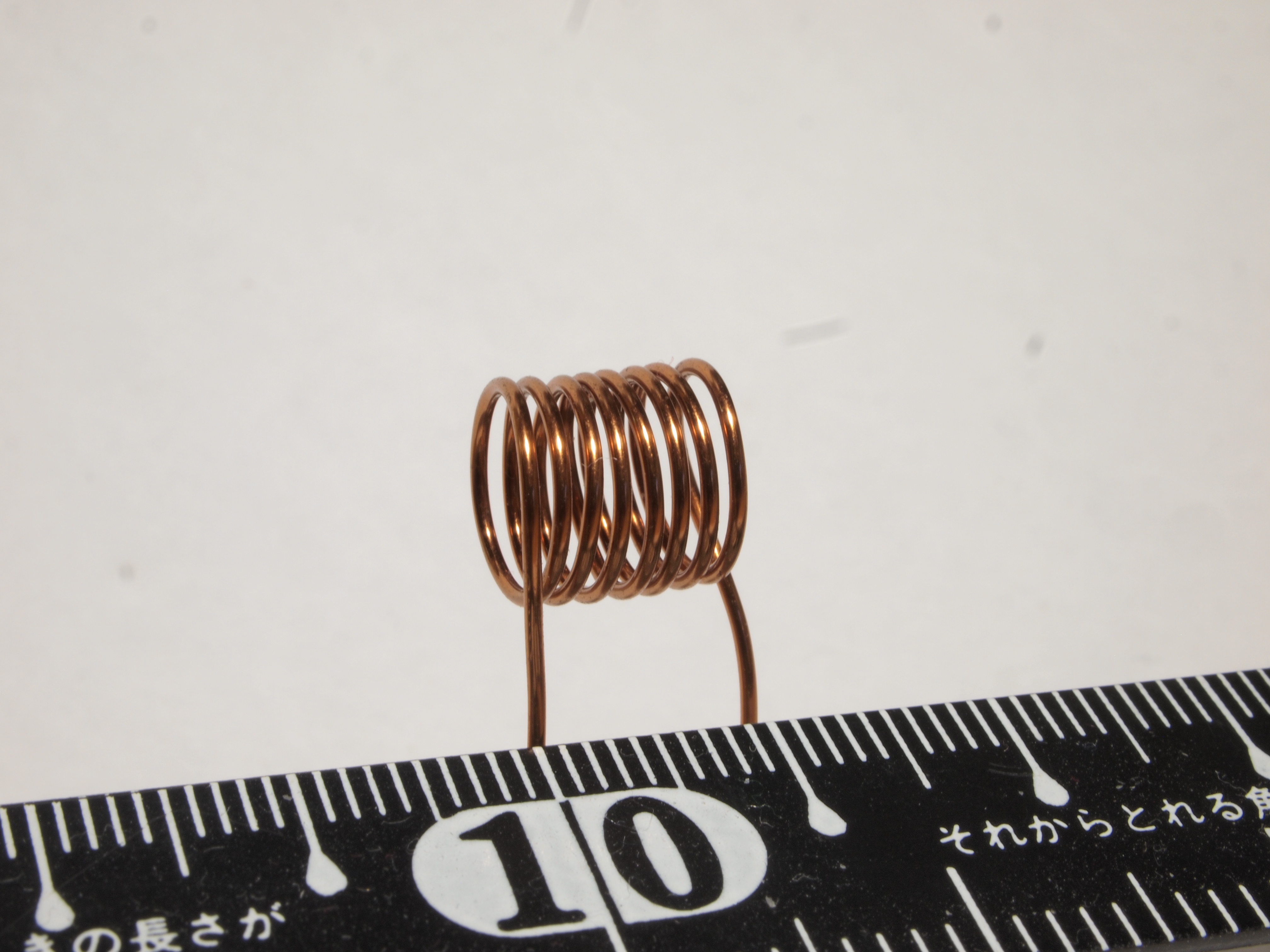
1.1 The One-Sentence Answer, and Then the Everyday One
An inductor is a device that stores energy in the magnetic field created by an electric current flowing through a winding of wire. That is the sentence to carry away if only one sentence survives. Everything else in this volume — and, arguably, in the thirteen that follow — is an unpacking of it: what “stores energy in a magnetic field” actually means, why the wire has to be coiled rather than run straight, why coiling it turns a nearly-inert length of copper into a component with a personality, and why a part whose whole job is to resist change is nonetheless found in almost every radio, power supply, and motor ever built.
The everyday physical reality is simpler than the sentence. Take a length of insulated wire and wind it into a series of loops — a coil, a helix, a spring of copper — and pass a current through it. That is an inductor. Often the coil is wound on a core: a rod, ring, or shaped block of iron, powdered iron, or ferrite (a hard, dark ceramic full of iron oxide) that concentrates the magnetic field and multiplies the effect. Sometimes there is no core at all, just wire and air. Either way the object is doing something quietly remarkable: the moving charge in the wire throws a magnetic field into the space around and through the coil, that field holds energy, and — this is the interesting part — the coil fights any attempt to change the current, because changing the current means changing the field, and the field does not like to be shoved around.
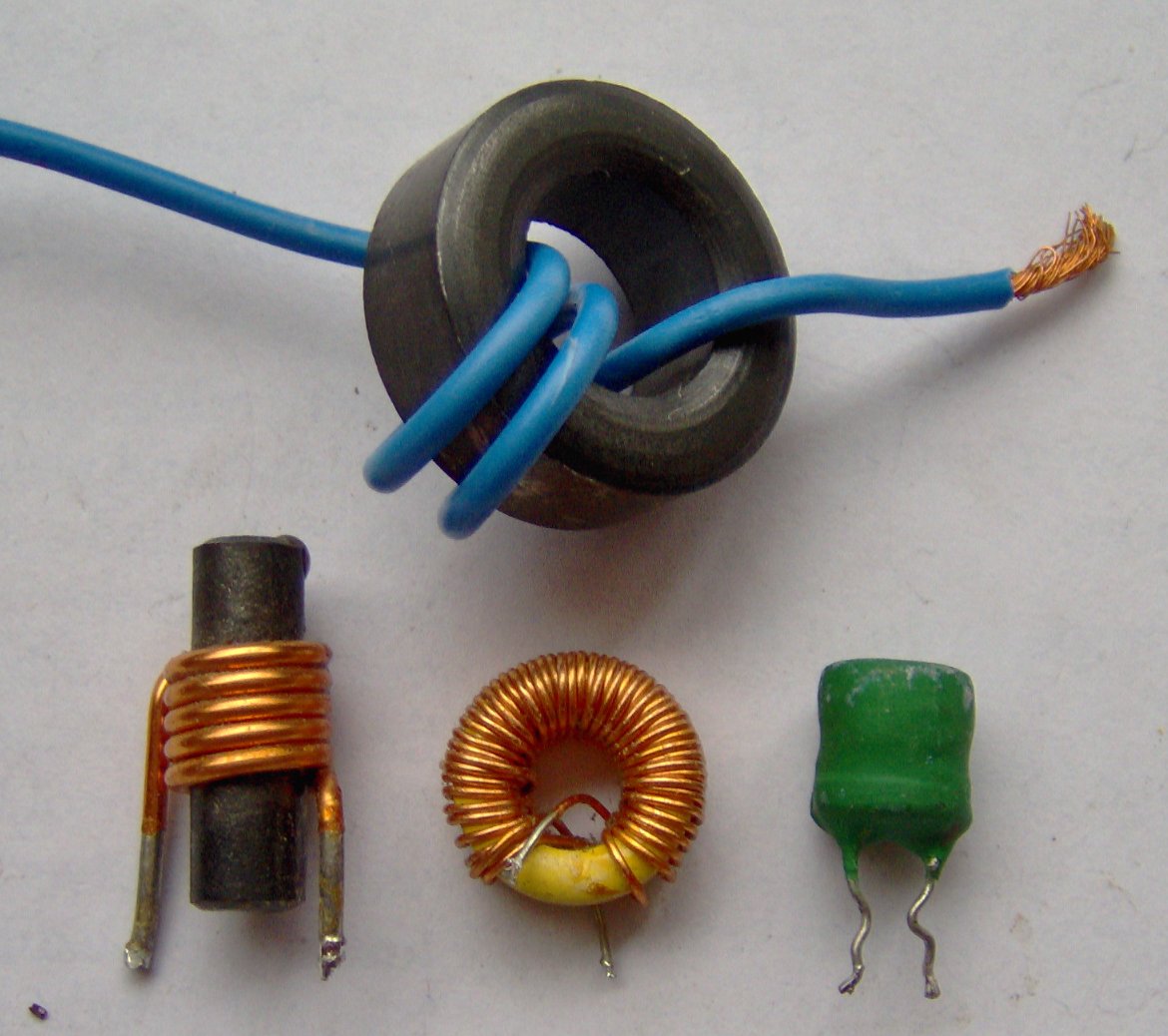
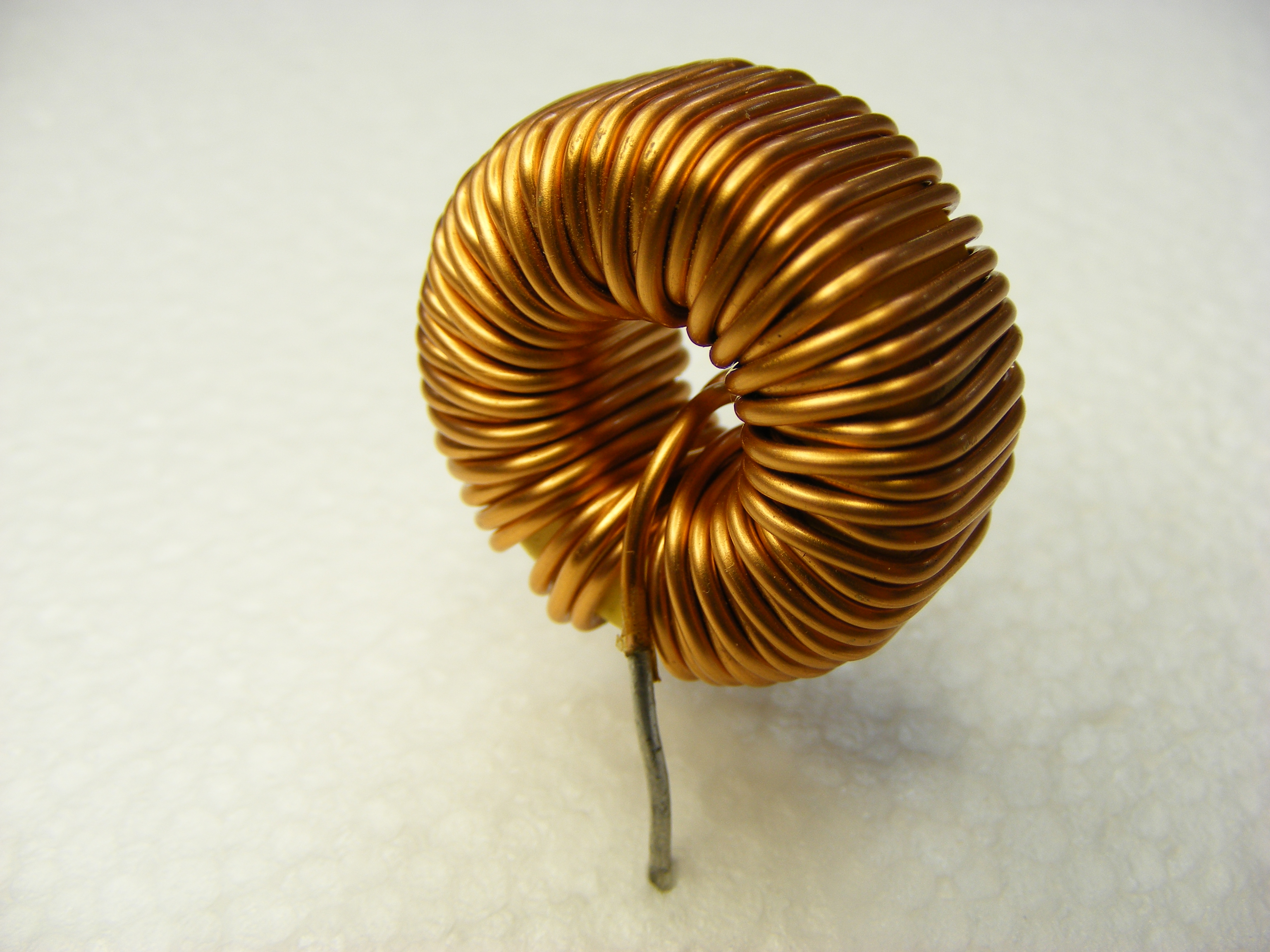
The photograph is a fair warning about how much variety hides behind that one idea. The fat ferrite ring, the little rod with a few turns on it, the doughnut wound tight with enamelled copper, the anonymous green blob — these are all inductors, and they range in value across more than nine orders of magnitude, from a fraction of a nanohenry up to hundreds of henries. A designer picks between them for reasons this series exists to explain. But every one of them is, at heart, a coil of wire, and every one obeys the same short handful of equations introduced below. Get those into the bones and the rest of the field becomes a story of engineering trade-offs rather than a bag of unrelated parts.
This is the companion piece to a parallel dive on the capacitor, and the two components are close relatives worth holding side by side. A capacitor stores energy in an electric field, in the gap between two conductors, and it resists a change in voltage. An inductor stores energy in a magnetic field, around a current-carrying coil, and it resists a change in current. They are mirror images — duals, in the language of circuit theory — and much of what one learns about the one illuminates the other. Where the capacitor volume reached for a stretched rubber membrane, the coil’s analogy is a spinning flywheel. Keep the pairing in the back of the mind; it pays dividends all the way through.
A note on an old word before proceeding. A coil used specifically to block or smooth alternating current has, for a century, been called a choke — because it “chokes off” the AC while letting DC pass. The term survives everywhere: the “choke” in a tube amplifier’s power supply, the “RF choke” that keeps radio-frequency signal out of a DC feed, the “common-mode choke” on a USB cable. It is not a different component; it is an inductor doing a particular job, and the reason it can do that job is the whole subject of the section on reactance below.
1.2 The Magnetic Field of a Current
To understand why coiling the wire matters, one has to start with the plain fact that started the whole science: an electric current produces a magnetic field. This was not obvious and was not predicted; the Danish physicist Hans Christian Ørsted noticed in 1820 that a compass needle twitched when he switched a nearby current on and off, and the magnetic and electric worlds — until then separate — were suddenly one subject. Every inductor is a machine built on Ørsted’s twitch.
1.2.1 A Straight Wire
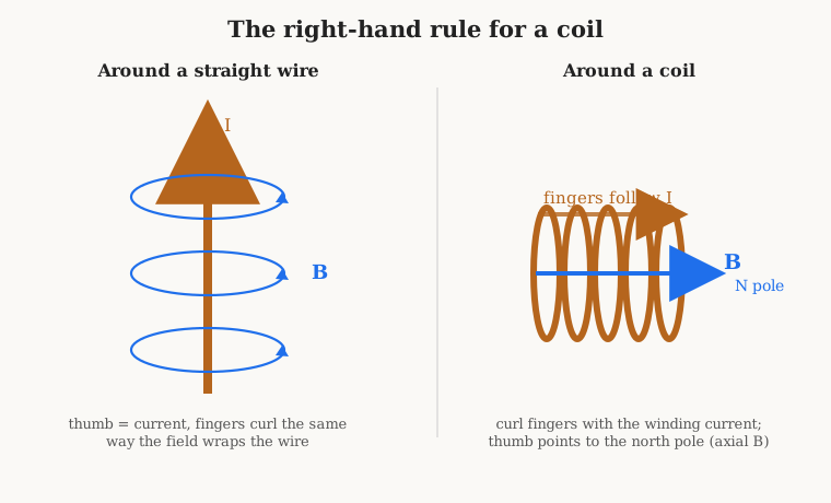
Run a steady current down a single straight wire and a magnetic field appears, wrapped around the wire in concentric circles, like the growth rings of a tree seen end-on. The field has a direction, given by the right-hand rule: point the thumb of the right hand along the direction of current flow, and the curled fingers show the way the magnetic field circulates around the wire. Reverse the current and the field reverses with it. The field is strongest right at the wire’s surface and weakens with distance — it falls off in proportion to one over the distance from the wire — so a single straight conductor is a feeble magnet. Useful as a starting point, useless as a component. The field is there, but it is smeared thinly through all the space around the wire and mostly points in unhelpful directions.
1.2.2 Coiling Concentrates It: the Turns Add
Here is the trick that makes the component. Bend that straight wire into a loop, and the circulating field from every part of the loop now points the same way through the middle of the loop — the contributions that were scattered around a straight wire are gathered and aimed through the loop’s centre. One loop makes a modest field through its own middle. Now stack a second loop beside the first, carrying the same current, and its field adds to the first’s. Stack a hundred loops into a tight helix and the fields of all hundred turns pile up along the common axis. This is the meaning of the phrase “the turns add.” The field down the axis of a coil is, to good approximation, proportional to the number of turns times the current — the quantity N·I, which engineers call the ampere-turns and treat as the true “magnetic drive” of the coil. Twenty turns carrying one amp and one turn carrying twenty amps produce the same magnetic push. That equivalence is exactly why we wind coils: turns are a cheap way to buy magnetic effect without paying for more current.
1.2.3 The Solenoid, Field Lines, and the North Pole
A long, straight, uniformly wound coil is called a solenoid — from the Greek for “pipe-shaped” — and it is the archetype every inductor formula is built on. Inside a solenoid the piled-up fields of all the turns produce a magnetic field that is strong, nearly uniform, and aligned neatly along the axis. Outside, the field spreads out, loops around from one end of the coil to the other, and returns — exactly the pattern a bar magnet makes, which is no coincidence, because a current-carrying solenoid is a magnet, an electromagnet, with a north pole at one end and a south pole at the other. Switch the current off and the magnetism vanishes; that on-demand magnetism is what makes the solenoid the workhorse of relays, valves, and door latches.
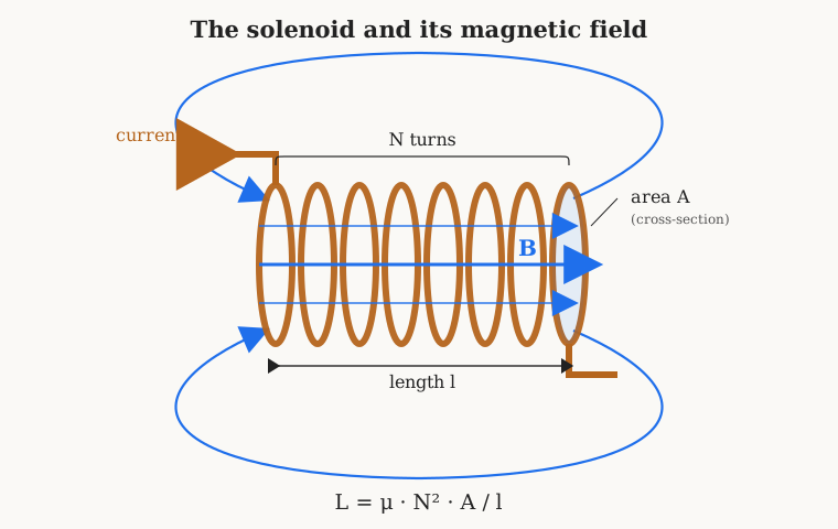
The looping lines drawn in the figure are field lines (or flux lines), and it is worth being clear about what they are and are not. They are a bookkeeping device invented by Michael Faraday to make an invisible field visible on paper. The direction of a line at any point is the direction a tiny compass would point there; the density of the lines — how crowded they are — represents the strength of the field, symbol B, measured in teslas (T). Crowded lines inside the solenoid mean a strong field; sparse lines out in the room mean a weak one. The total number of lines threading through the coil — the field strength B multiplied by the area A it passes through — is the magnetic flux, symbol Φ (the Greek letter phi), measured in webers (Wb). Flux is the quantity that matters most for an inductor, because, as the next section shows, it is changing flux that gives the component its entire character. One weber, one tesla, one henry: these three units are wired together, and the wire between them is Faraday’s law.
1.3 Faraday, Lenz, and Why Current Has Inertia
Everything so far has been static — a steady current making a steady field. The moment the current changes, the inductor comes alive, and it does so through the single most consequential law in this subject.
1.3.1 Faraday’s Law: a Changing Field Makes a Voltage
Faraday discovered in 1831 that a changing magnetic flux through a loop of wire creates a voltage — an electromotive force, or EMF — around that loop. Not a steady field; a changing one. Hold a magnet still inside a coil and nothing happens; move it, and a voltage appears at the coil’s ends for exactly as long as it is moving. The faster the flux changes, the bigger the voltage. In symbols, the induced EMF equals the rate of change of flux, multiplied by the number of turns the flux threads:
EMF = −N · (dΦ/dt)
The N is there because each turn of the coil feels the changing flux, and the turns are in series, so their voltages add — turns multiply the effect here just as they did for the field. The dΦ/dt is calculus shorthand for “how fast the flux is changing”; if the reader has not touched a derivative in decades, read it simply as the rate of change of the flux, in webers per second. A weber per second is, by definition, one volt. That is the whole content of Faraday’s law: shove the flux hard and fast, get a big voltage.
Now comes the twist that makes an inductor an inductor rather than a mere sensor. In a coil, the flux is being made by the coil’s own current. So if the current through the coil changes, its own flux changes, and by Faraday’s law the coil induces a voltage in itself. This is self-induction, and the voltage it produces is called the back-EMF. The coil is reacting to its own change of mind.
1.3.2 Lenz’s Law: the Coil Always Fights the Change
Which way does the back-EMF point? The answer is a law all its own, stated by Heinrich Lenz in 1834, and it is the source of the minus sign in Faraday’s equation: the induced voltage always opposes the change that produced it. If the current is rising, the back-EMF pushes against the rise, trying to hold the current down. If the current is falling, the back-EMF pushes to keep it flowing, propping the current up. The coil is a contrarian. Whatever the circuit tries to do to the current, the inductor pushes back the other way — not permanently, but for as long as the change is under way.
This is not a small technicality; it is the entire personality of the component, and it is worth restating in plain words: an inductor resists changes in the current through it. You cannot make the current in an ideal inductor jump instantly, because an instant jump would be an infinitely fast change of flux, which by Faraday’s law would demand an infinite voltage to drive it, and infinite voltages are not on offer. Current in an inductor is therefore smooth — it can rise and fall, but only at a rate the available voltage allows. This is the exact dual of the capacitor, whose voltage cannot jump instantly; in the inductor it is the current that has continuity.
1.3.3 The Flywheel Analogy, Done Properly
The cleanest intuition for this behaviour is mechanical: an inductor is to current what mass is to velocity. Current has inertia. A heavy flywheel resists being sped up or slowed down; you have to push on it (apply a force) for a while to get it spinning, and once it is spinning it wants to keep going and will resist being stopped. An inductor does exactly the same thing to current. The correspondences are precise enough to be useful:
Table 1 — The cleanest intuition for this behaviour is mechanical: an inductor is to current what mass is to velocity. Current has inertia. A heavy flywheel resists being sped up or slowed down; you have to push on it (apply a force) for a while to get it spinning, and once it is spinning it wants to keep going and will resist being stopped. An inductor does exactly the same thing to current. The correspondences are precise enough to be useful
| Mechanical (flywheel) | Electrical (inductor) |
|---|---|
| Mass / moment of inertia, m | Inductance, L |
| Velocity, v | Current, I |
| Force, F | Voltage, v |
| Kinetic energy, ½·m·v² | Stored energy, ½·L·I² |
| F = m·(dv/dt) (Newton) | v = L·(di/dt) |
Read down that table and the physics falls out. Just as a force is needed to accelerate a mass (F = m·dv/dt), a voltage is needed to change the current in an inductor (v = L·di/dt). Just as a spinning flywheel stores kinetic energy ½·m·v², a current-carrying inductor stores energy ½·L·I². Just as a heavy flywheel takes longer to spin up for a given push, a large inductance takes longer for the current to build for a given voltage. A layman who has ever pushed a stalled car — hard to get moving, then hard to stop — already has a working feel for inductance in the muscles.
Where does the analogy break? In three honest places, each worth naming. First, a real flywheel loses energy to friction and bearing drag; the analogous “friction” in a real inductor is the resistance of its own copper wire, which is not part of the ideal picture and gets a volume of its own later in this series. Second, and more subtly, the analogy hides where the energy actually lives. It is tempting to say the energy is “in the coil,” the way the kinetic energy is “in the flywheel,” but the electrical truth is stranger: an inductor’s energy is stored in the magnetic field in the space around and through the coil, not in the copper and not in the moving electrons. Cut the field’s path — put a gap in the core, or unwind the coil — and the energy has nowhere to sit. Third, mass is a fixed property of an object, but inductance is a property of geometry and material, and in a coil with an iron core it is not even constant: drive the core hard enough and it saturates, the inductance collapses, and the “mass” of the current suddenly drops out from under the circuit. That failure mode — saturation — is a recurring villain in later volumes. For now, the flywheel is the right picture, provided one remembers it is a picture.
1.4 Inductance and the Henry
The flywheel table already smuggled in the defining equation, so let us make it official. Inductance, symbol L, is the constant of proportionality between the voltage across a coil and the rate of change of the current through it:
v = L · (di/dt)
In words: the voltage an inductor develops is its inductance times how fast its current is changing. Push the current to change quickly (large di/dt) and a large voltage appears; hold the current steady (di/dt = 0) and the inductor develops no voltage at all — a steady current sees an ideal inductor as a plain piece of wire. Inductance L is the number that says how strongly a given coil converts a rate-of-change-of-current into a voltage. A big L is a coil that reacts violently to any attempt to change its current; a small L barely notices.
1.4.1 The Henry, and Why It Is Large
The unit of inductance is the henry (H), named for the American physicist Joseph Henry, who discovered self-induction independently of and around the same time as Faraday. From the defining equation, one henry is one volt-second per amp: 1 H = 1 V·s/A. Put concretely, a one-henry inductor develops one volt across itself when its current changes at a rate of one amp per second. Equivalently, in flux terms, one henry is one weber of flux linkage per amp of current — the two definitions are the same law seen from two ends.
The henry, like the capacitor’s farad, is a large unit for everyday electronics. A whole henry is a serious lump of iron and copper — the kind of thing found as a filter choke in a vintage tube amplifier’s power supply, physically the size of a small transformer. The inductors on a typical circuit board live far below that, and fluency in the prefixes is the first bench skill:
Table 2 — The henry, like the capacitor's farad, is a large unit for everyday electronics. A whole henry is a serious lump of iron and copper — the kind of thing found as a filter choke in a vintage tube amplifier's power supply, physically the size of a small transformer. The inductors on a typical circuit board live far below that, and fluency in the prefixes is the first bench skill
| Prefix | Symbol | Fraction of a henry | Typical home |
|---|---|---|---|
| millihenry | mH | 10⁻³ (one thousandth) | power-supply chokes, audio inductors, larger RF coils |
| microhenry | µH | 10⁻⁶ (one millionth) | switching-regulator inductors, RF tuning coils |
| nanohenry | nH | 10⁻⁹ (one billionth) | VHF/UHF coils, PCB-trace and bead inductance, parasitics |
Each step is a factor of a thousand: 1 mH = 1000 µH = 1 000 000 nH. A switching power supply might use a 10 µH inductor; the tuned circuit in an AM radio, a few hundred µH; the tiny coil setting the frequency of a VHF oscillator, perhaps 100 nH. And at the very bottom, the nanohenry stops being a component value and becomes a parasite: a straight length of wire has an inductance of very roughly a nanohenry per millimetre, which sounds negligible until one is working at hundreds of megahertz, where a centimetre of lead wire is a real inductor whether anyone wanted it or not. The volume on the real, non-ideal inductor returns to that unwelcome guest.
1.4.2 What Determines L: the N-Squared Surprise
Inductance is not adjusted by turning a knob; it is built in by the coil’s shape and material. For the archetypal solenoid — the long uniform coil of Figure 3 — the inductance is captured by a compact and famous formula:
L = µ · N² · A / l
Each term earns its place, and each has a plain-English meaning:
- N is the number of turns of wire. Note it appears squared — the single most important and least intuitive feature of the whole formula, worth its own paragraph below.
- A is the cross-sectional area enclosed by the turns, in square metres — how much room the field has to fill inside the coil. Fatter coil, more inductance.
- l is the length of the winding, in metres. A longer coil (turns spread out) has less inductance, because the field is diluted along a greater length; packing the same turns into a shorter coil raises L.
- µ (the Greek letter mu) is the permeability of whatever fills the coil’s core — a measure of how readily that material carries magnetic flux. It splits into two factors, µ = µ₀ · µᵣ. The first, µ₀, is the permeability of free space, a fixed constant of nature (about 1.257 × 10⁻⁶ henries per metre) that sets the baseline for a vacuum or, near enough, air. The second, µᵣ, is the relative permeability of the core material: a pure number saying how many times better than air that material carries flux. Air is µᵣ = 1; a ferrite might be a few hundred to a few thousand; a good iron or permalloy alloy, tens of thousands. Slide an iron core into an air coil and the inductance leaps by that factor, which is precisely why so many inductors have cores. The volume on core materials is devoted to this one term.
Now the surprise. Why is N squared? Doubling the turns does not double the inductance; it quadruples it. The reason is that turns do double duty, and each duty contributes one factor of N. First, more turns make a proportionally stronger field for a given current — that is the ampere-turns from earlier, one factor of N. Second, more turns means more loops of wire for that field to thread through, so each unit of field is linked more times — a second factor of N, from the same N in Faraday’s law. Field strength scales with N, and flux linkage scales with N again; multiply them and inductance scales with N². This is the single most useful fact a coil-winder can hold: if a coil measures a bit low, adding 10% more turns raises the inductance by about 21%, not 10%; halving the turns quarters the inductance. Every turns-for-a-target-value calculation in the design volume, and every trimming decision at the winding machine, runs on that squared relationship.
Two cautions keep the formula honest. It is the ideal long-solenoid result, and it over-estimates real coils, because the field bulges and weakens at the ends of any finite coil; a short, fat coil can be off by a large margin, and the design volume replaces this expression with Wheeler’s corrected formulas for practical work. And it treats µ as a constant, which for an air core it is, but for an iron or ferrite core it emphatically is not — µ sags as the core saturates and varies with temperature and frequency. As an intuition-builder, though, L = µN²A/l is exactly right: inductance goes up with permeability, up with area, up with the square of the turns, and down with length. Those four levers are the only ones a coil designer has, and the entire craft is a matter of pulling on them cleverly.
1.5 Energy in the Field, and the Spark on the Switch
An inductor carrying a current I is holding energy, and the amount is the electrical twin of the flywheel’s kinetic energy:
E = ½ · L · I²
with E in joules when L is in henries and I in amps. As with the flywheel, the energy scales with the square of the “speed” — double the current and the stored energy quadruples. And, to hammer the point made earlier, that energy is not sitting in the copper or in the electrons; it is stored in the magnetic field occupying the space in and around the coil. The copper is merely the scaffolding that shapes the field. This is not a philosophical nicety. It has a consequence so practical, and occasionally so painful, that every engineer meets it early — usually the hard way.
Consider a switch feeding an inductor. Close the switch and current builds smoothly, the field grows, energy accumulates in it. Now open the switch. The current, which was flowing happily, is suddenly ordered to stop — to drop to zero in the near-zero time it takes the contacts to part. But Lenz’s law forbids an instantaneous change in inductor current: the coil will do whatever it takes to keep its current flowing. What it takes, by v = L·di/dt, is voltage — and because di/dt is enormous (a large current vanishing in a tiny time), the voltage the coil generates is enormous too, far larger than the supply that was driving it. This is the inductive kick, or flyback: the collapsing field dumps its stored energy into a brief, savage voltage spike. If there is an air gap in the circuit — the opening switch contacts — the spike will happily rip across it as a spark, and the energy ½LI² discharges as a tiny lightning bolt.
That spark is not always a fault; sometimes it is the entire point. The ignition coil in a petrol engine is an inductor (strictly, a transformer, treated in the coming transformers dive) whose primary current is deliberately interrupted so that the flyback produces tens of thousands of volts, enough to jump the spark plug gap and light the fuel. The same physics runs every boost and flyback switching power supply, where a transistor chops the current in an inductor thousands of times a second and the flyback voltage is harvested to step a voltage up. Inductive kick is a tool.
But uncontrolled, it is a menace, and this is the load-bearing safety note of the volume. The spike from an interrupted inductor can be hundreds or thousands of volts even in a circuit running from a few volts, and it will cheerfully destroy the transistor or contact that tried to switch it, arc across relay points and erode them, or inject a burst of interference into everything nearby. The standard defence is a flyback diode (also called a freewheeling or catch diode) wired across the inductor, backwards to the normal current so it does nothing in ordinary operation. The instant the switch opens and the coil’s voltage reverses to keep its current flowing, the diode becomes forward-biased and offers that current a harmless path, letting it circulate and decay gently through the diode instead of arcing across the switch. Any relay or solenoid driven by a transistor wants one; leaving it out is a classic way to kill a microcontroller’s output pin. The blunt rule for the bench: an inductor with current in it is a loaded spring, and opening its circuit lets the spring go. Respect it, and give the energy a door to leave by.
1.6 Reactance and Frequency: Why a Coil Is a “Choke”
So far the inductor has been described in the time domain — currents rising and falling, sparks on switches. But a great deal of electronics runs on alternating current, signals that swing up and down continuously, and there the inductor’s behaviour is best described by a single frequency-dependent number. Because an inductor develops voltage in proportion to how fast its current changes, and because a faster alternating current (a higher frequency) changes faster, an inductor opposes AC more and more strongly as the frequency climbs. This frequency-dependent opposition is called inductive reactance, symbol XL, measured in ohms like a resistance, and it is given by a clean and much-used formula:
XL = 2 · π · f · L
where f is the frequency in hertz and L the inductance in henries. The 2π converts from cycles per second to the “radians per second” the underlying calculus prefers; treat it as a fixed part of the recipe. The message of the formula is that reactance rises in direct proportion to frequency: double the frequency and an inductor opposes the current twice as hard. Worked through for a small 25 µH coil, its reactance is only about 16 ohms at 100 kHz but climbs to roughly 160 ohms at 1 MHz and 1600 ohms at 10 MHz. The same coil that is nearly a dead short to a low-frequency signal becomes a substantial obstacle to a high-frequency one.
The two extremes are worth stating plainly because they are the source of the word “choke.” At DC — zero frequency — the reactance XL is exactly zero. A steady current changes not at all, the inductor develops no voltage, and the coil looks like what it physically is: a length of wire, opposing the current only by the modest resistance of its own copper (its DC resistance, or DCR). An inductor passes DC freely. At high frequency, by contrast, the reactance grows without limit, and the inductor increasingly blocks the current. Put those two facts together and the component sorts a mixed signal by frequency: it waves the DC and low frequencies through while choking off the high frequencies. That is exactly the job of a choke — a power-supply choke passes the DC the circuit needs while blocking the AC ripple one wants to keep out; an RF choke feeds DC to a transistor while stopping the radio-frequency signal from leaking away down the supply line.
This is the precise opposite of a capacitor’s behaviour, and the contrast is the fastest way to remember both. A capacitor blocks DC and passes high frequencies (its reactance falls with frequency); an inductor passes DC and blocks high frequencies (its reactance rises with frequency). One is the frequency mirror of the other — the duality again. It is no accident that filters are built by pairing them: an inductor in series with a load and a capacitor across it makes a low-pass filter almost by inspection, the inductor blocking high-frequency series current while the capacitor shunts away whatever gets through. The volume on where inductors are used builds real filters on exactly this seesaw. And when an inductor and capacitor are placed together in a loop, their opposite reactances cancel at one special frequency, producing resonance — the sharply selective tuned circuit that lets a radio pick one station out of the air. That resonance is the reason coils and radios grew up together, and it earns its own extended treatment later.
1.7 DC vs AC and the L/R Time Constant
Return from the steady hum of AC to the moment a DC circuit is switched on, because it exposes the inductor’s inertia most vividly and introduces a number the engineer uses constantly. Connect a battery of voltage V through a resistor R to an inductor L, and close the switch. In a purely resistive circuit the current would snap instantly to V/R. With the inductor present it cannot: Lenz’s law forbids the jump, so the current rises smoothly from zero, fast at first and then ever more gently, easing up to its final value V/R as if reluctant to arrive. Open the switch (with a path for the current to keep flowing, such as a flyback diode) and the current decays along the same kind of curve, quickly at first and then trailing off toward zero.
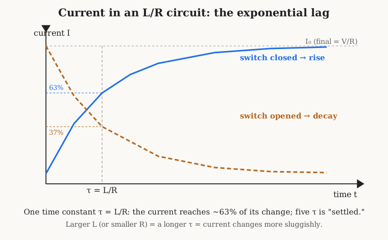
The shape of that curve is a mathematical exponential, and its pace is set by a single quantity, the time constant, symbol τ (the Greek letter tau):
τ = L / R
with τ in seconds when L is in henries and R in ohms. The time constant is the natural clock of the circuit. In one time constant the current covers about 63% of its total change (rising from zero, it reaches 63% of V/R; decaying, it falls to 37% of where it started). After two time constants it has covered about 86%, after three about 95%, and by five time constants it is within a fraction of a percent of its final value — the engineer’s practical definition of “settled.” A large inductance or a small resistance makes τ long and the current sluggish; a small inductance or a large resistance makes τ short and the current nimble. This is the direct dual of the capacitor’s RC time constant, which sets how fast a capacitor charges through a resistor; the two share the same exponential curve and the same 63%/37% landmarks, with L/R standing in for RC. An engineer who has the RC time constant in the fingers already has this one — it is the same idea wearing the other component’s clothes.
1.8 Reading the Symbols
An inductor announces itself on a schematic by a distinctive squiggle: a short series of loops or humps drawn along the wire, a stylised side-view of the coil itself. Learning to read the small marks around that squiggle lets one tell at a glance what kind of coil a designer intended and, often, what job it is doing.
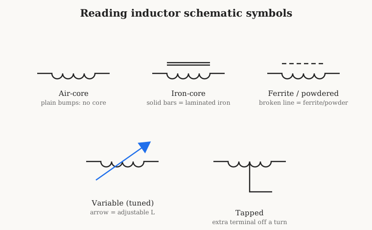
The bare series of loops, with nothing beside it, is an air-core inductor — no magnetic core, just wire and air, the choice for radio-frequency work where core losses would be intolerable. Two solid parallel bars drawn alongside the loops signify a solid magnetic core, conventionally laminated iron, the mark of a heavy low-frequency choke or an audio inductor. A broken or dashed line beside the loops means a ferrite or powdered-iron core — the near-universal choice for the switching-supply and RF inductors on a modern board, the dashes hinting at the granular, non-solid nature of the material. A diagonal arrow drawn through the symbol marks a variable inductor, one whose value can be adjusted — classically by screwing a threaded ferrite slug in and out of the coil to tune it. And an extra terminal brought out from a point partway along the winding makes a tapped inductor, letting a circuit access a fraction of the turns, common in impedance-matching networks and older radios.
The practical eye learns two quick reads. A coil drawn with many loops and a core mark, sitting between a supply and a load or across a power rail, is almost certainly a choke, there to block AC or smooth ripple. A coil drawn near a capacitor, often air-core or slug-tuned, forming a loop with it, is almost certainly part of a tuned circuit, there to select a frequency. Same squiggle, opposite jobs — and telling them apart from context is a skill that comes fast once the two archetypes are in mind.
1.9 Why Coils Matter — and Why We Still Wind Them
Having built the inductor up from the magnetic field, it is worth stepping back to survey what the component does, because the applications are the reason the following thirteen volumes exist. Inductors are the beating heart of every tuned circuit and filter: paired with capacitors, they select frequencies, which is how every radio, television, and wireless device ever built picks its signal out of the ether. They serve as chokes, passing DC and wanted signals while blocking AC and interference, cleaning up power supplies and isolating stages. They are the energy-storage element in every switching power supply, the little coils that let a laptop charger or a phone convert one DC voltage efficiently to another by repeatedly storing energy in a magnetic field and releasing it. They are the core of EMI suppression — the ferrite beads clamped on cables and the common-mode chokes on power leads that soak up electrical noise. They sense position and current, they transfer power across an air gap in a wireless charger, and, wound as a pair on a shared core, they become the transformer that steps voltages up and down across the entire electrical grid — the subject of the companion dive to come.
And here is the fact that shapes this entire deep dive, and separates it from its sister volume on the capacitor. The capacitor, for the most part, is a triumph of mass production: the tiny multilayer ceramic chip capacitor is made by the trillion, stacked and fired by machines no human hand touches, and one simply buys the value one needs. Many inductors are not like that. Because inductance is a matter of turns and geometry and core, an enormous number of inductors — the RF coil in a transmitter, the choke in a tube amplifier, the toroid in a ham-radio antenna tuner, the custom transformer in a piece of test gear — are still wound, turn by turn, sometimes on a machine and sometimes by hand. The value one wants may not exist as a stock part, or the core one has demands a particular number of turns, or the job is a one-off repair of something built decades ago. Winding a coil is a craft with real technique — tension, turns-counting, layering, the geometry of a toroid, the choice of wire — and it is a craft the builder can actually practise on a bench with a hand winder or a motorised one.
That is why this series spends real time on the coil-winding machines and the technique of winding — the hand and geared winders, the traverse and tensioning mechanisms, the bobbins and formers and mandrels, and worked projects wound on the actual machines. The volumes ahead build outward from the foundation laid here: the real, non-ideal inductor and its parasitic resistance, capacitance, and self-resonance; the history from Faraday and Henry through the induction coil and the Tesla coil to the modern magnetics industry; core materials and magnetics in depth; magnet wire and its gauges and insulations; the geometries of coils and the machines that wind them; the technique of winding; designing a coil for a target value; where inductors are used; the specialty and variable types; how to measure and test a finished coil; and a set of build-your-own projects. Every one of them rests on the one sentence this volume began with. An inductor stores energy in a magnetic field, and it resists a change in current — and from that single stubborn habit, the whole rich behaviour of the coil unfolds.
Comments (0)