Coils and Coil Winding · Volume 5
Magnet Wire and Conductors
5.1 The wire is the coil
Every earlier volume treated the winding as an abstraction: N turns, a certain inductance, a certain DC resistance. This volume is about the physical stuff those turns are actually made of — the thin, varnish-brown, faintly aromatic copper that comes off a spool and, wound onto a former, becomes the inductor. Get the wire wrong and nothing downstream is right: the coil runs too hot, does not fit the window, shorts turn-to-turn, refuses to solder, or throws away its Q the moment the frequency climbs. The winder who understands wire chooses gauge, insulation class, and (occasionally) Litz construction on purpose, and the coil comes out the size, temperature, and Q that the design asked for.
5.1.1 What magnet wire actually is
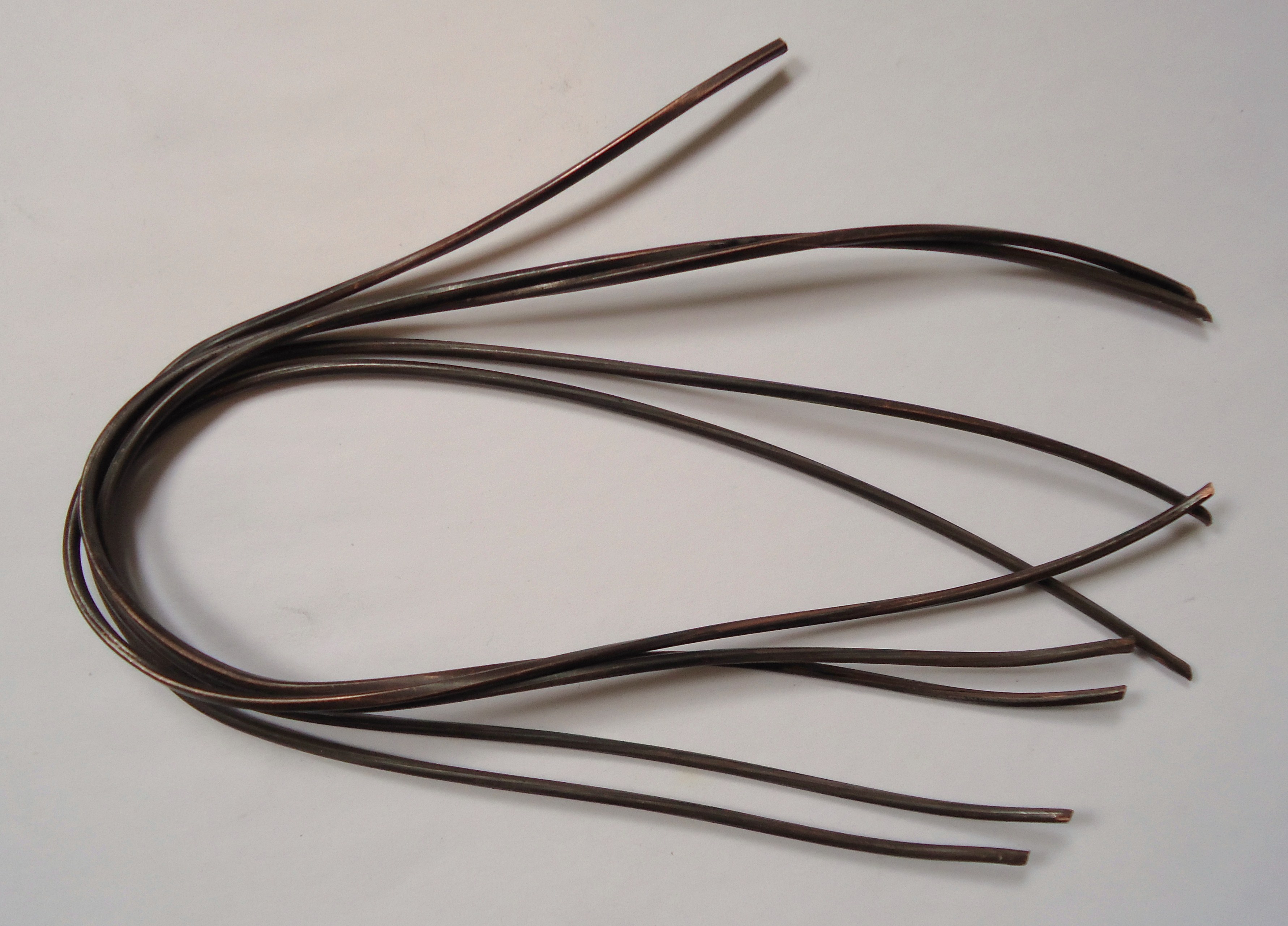
Magnet wire — also called enamelled wire, winding wire, or coil wire — is a solid metal conductor, almost always copper, coated with a thin, cured polymer film that serves as the turn-to-turn insulation. The word “enamel” is a historical holdover: the earliest films were oleoresinous varnishes baked onto the wire, and the name stuck even though every modern film is a synthetic polymer. What matters is the thinness. A piece of hook-up wire carries perhaps half a millimetre of extruded PVC or silicone on each side; magnet-wire film is measured in microns — tens of microns even on the heavier grades. That difference is the whole point. A coil is a race to get as much copper as possible into a fixed winding window, and every micron of insulation is copper you did not fit. The thin baked film lets adjacent turns sit essentially copper-to-copper-spacing apart, which is what makes a 1000-turn bobbin or a tightly coupled transformer physically possible. Thick plastic insulation would blow the turns count and the coupling out of reach.
The film has to do a real electrical job despite its thinness: it must withstand the voltage between adjacent turns. In most coils that inter-turn voltage is small — the supply divided across many turns — so a few microns of a good dielectric is plenty. It is only in high-voltage secondaries, flyback windings, and the first few turns of a switch-mode transformer (where the whole step edge lands across a handful of turns) that the film’s voltage rating and the build grade start to matter, a point the winding-technique volume returns to when it discusses interleaving and layer insulation.
Copper is the near-universal conductor because it combines high conductivity (the International Annealed Copper Standard, 100% IACS, is literally defined by it) with solderability, ductility for winding, and reasonable cost. Aluminium magnet wire exists and is used in large motors, some line-frequency transformers, and cost-driven mass production. Aluminium has roughly 61% of copper’s conductivity, so for the same resistance it needs about 1.6 times the cross-sectional area — a bigger, bulkier winding. Its trump card is weight and price: aluminium is about a third of copper’s density, so an aluminium winding of equal resistance weighs roughly half as much and, historically, costs far less per unit conductance. It is also harder to terminate — the tenacious oxide skin means aluminium does not solder happily and is usually welded, crimped, or joined with special techniques. For a hand or bench winder building coils, copper is the default and aluminium is a curiosity; the volume assumes copper unless it says otherwise.
5.2 AWG: the wire-gauge system
American Wire Gauge (AWG), also called Brown & Sharpe gauge, is the numbering system that names round copper wire in North America. Its one counter-intuitive rule trips up every newcomer: the bigger the number, the thinner the wire. AWG 10 is a sturdy 2.6 mm conductor you could wind a power choke with; AWG 40 is a gossamer 0.08 mm hair you can barely see. The numbering runs backwards because it originally counted the number of draws through progressively smaller dies — more draws, thinner wire, higher number.
Underneath the backwards counting is a clean geometric progression. AWG is defined so that the diameter changes by a fixed ratio per gauge step. Going from the largest practical size (4/0) down to AWG 36 spans 39 steps and a diameter ratio of 92, so each single gauge step multiplies the diameter by the 39th root of 92 — about 1.123. Two consequences fall straight out of that and are worth memorising because they let a winder do gauge arithmetic in their head:
- Every 6 gauges, the diameter changes by 2× (1.123 to the 6th power ≈ 2.0). So AWG 10 is twice the diameter of AWG 16, which is twice AWG 22, and so on.
- Every 3 gauges, the cross-sectional area changes by 2×, and therefore every 3 gauges the DC resistance changes by 2× as well (area up, resistance down). Ten gauges is close to a factor of 10 in area and resistance — AWG 10 has roughly ten times the copper and one-tenth the resistance of AWG 20.
Cross-sectional area in the American system is traditionally quoted in circular mils (a circular mil is the area of a circle one mil — one thousandth of an inch — in diameter). The convenience is that the area in circular mils is simply the diameter in mils squared, no π required. AWG 10 is about 101.9 mils in diameter, hence about 10,380 circular mils. That unit reappears below in the current rule of thumb.
A word on the rest of the world. Outside North America, magnet wire is very often sized directly by its bare diameter in millimetres — “0.5 mm wire,” “0.315 mm wire” — which sidesteps the gauge numbering entirely and is arguably more honest. Britain and the Commonwealth historically used SWG (Standard/Imperial Wire Gauge), a different progression from AWG: an SWG number does not equal the same-numbered AWG size, so a data sheet or a coil recipe must state which gauge system it means. When following a vintage British radio winding recipe, treat the gauge column as SWG until proven otherwise, or the turns count will be off.
5.2.1 The AWG reference table
The table below covers the sizes a coil winder actually reaches for, AWG 10 through 44. Diameter and area are the bare copper conductor (before enamel); the overall diameter with film is larger and depends on the build grade (discussed next). DC resistance is for annealed copper at 20 °C. The “current at 700 CM/A” column is not an ampacity rating — it is the current at a single, deliberately conservative rule-of-thumb loading of 700 circular mils per ampere, included only to give a feel for scale; the section after it explains why there is no honest single ampacity for magnet wire.
Table 1 — The AWG reference table
| AWG | Bare dia (mm) | Area (mm²) | Area (cmil) | Ω / 1000 ft | Ω / km | Current @ 700 CM/A |
|---|---|---|---|---|---|---|
| 10 | 2.588 | 5.26 | 10,380 | 0.999 | 3.28 | 15 A |
| 12 | 2.052 | 3.31 | 6,530 | 1.588 | 5.21 | 9.3 A |
| 14 | 1.628 | 2.08 | 4,110 | 2.525 | 8.28 | 5.9 A |
| 16 | 1.290 | 1.31 | 2,580 | 4.016 | 13.17 | 3.7 A |
| 18 | 1.024 | 0.823 | 1,620 | 6.385 | 20.9 | 2.3 A |
| 20 | 0.813 | 0.518 | 1,020 | 10.15 | 33.3 | 1.5 A |
| 22 | 0.645 | 0.326 | 640 | 16.14 | 52.9 | 0.92 A |
| 24 | 0.511 | 0.205 | 405 | 25.67 | 84.2 | 0.58 A |
| 26 | 0.404 | 0.129 | 255 | 40.81 | 133.9 | 0.36 A |
| 28 | 0.320 | 0.081 | 160 | 64.90 | 212.9 | 0.23 A |
| 30 | 0.254 | 0.0507 | 100 | 103.2 | 338.5 | 0.14 A |
| 32 | 0.203 | 0.0324 | 63 | 164.1 | 538.3 | 91 mA |
| 34 | 0.160 | 0.0201 | 40 | 260.9 | 855.8 | 56 mA |
| 36 | 0.127 | 0.0127 | 25 | 414.8 | 1360 | 35 mA |
| 38 | 0.102 | 0.0081 | 16 | 659.6 | 2163 | 23 mA |
| 40 | 0.0787 | 0.0050 | 9.9 | 1049 | 3440 | 14 mA |
| 42 | 0.0635 | 0.0032 | 6.3 | 1652 | 5421 | 8.9 mA |
| 44 | 0.0508 | 0.0020 | 4.0 | 2589 | 8495 | 5.7 mA |
Source: Remington Industries solid-copper / magnet-wire AWG data (bare diameter, area, DC resistance at 20 °C; current column at 700 circular mils per ampere). Values are nominal; consult the specific manufacturer’s data sheet for guaranteed figures. The full standard runs from 4/0 down past AWG 50.
Two sanity checks confirm the geometric rules. AWG 10 → 20 is ten gauges: area falls from 5.26 to 0.518 mm² (≈ 10×) and resistance rises from 1.0 to 10.15 Ω/1000 ft (≈ 10×). AWG 20 → 26 is six gauges: diameter halves, 0.813 → 0.404 mm. The mental model holds across the whole table.
5.3 Current capacity and heating: there is no single “amps per gauge”
Newcomers want a table that says “AWG 24 is good for X amps.” For magnet wire in a coil, that table does not exist, and the reason is physics, not laziness. Ampacity is set by allowable temperature rise, and the temperature a winding reaches depends on how well it can shed heat — which for a coil is terrible. A single wire in free air convects and radiates from its whole surface. The same wire buried in the middle of a multi-layer winding, surrounded by other current-carrying turns and wrapped in varnish and a bobbin, sits at the bottom of a thermal well: the heat from every turn has to conduct out through layers of copper, film, and impregnant before it reaches air. A gauge that runs cool as a single strand can cook in the centre of a fat winding.
So the winder sizes wire from I²R heating and window fit, not from a fixed ampacity. The starting tool is the circular-mils-per-ampere rule of thumb. Pick a current density expressed as circular mils of copper per ampere:
- ~1000 CM/A — conservative; a winding that must run cool, poorly ventilated, or continuously loaded. (Higher CM/A = fatter wire = lower density = cooler.)
- ~500 CM/A — a typical, moderately loaded transformer or choke winding.
- ~300 CM/A or below — aggressive; short duty cycle, good cooling, or a design that tolerates a hot winding.
For a transformer the classic working range is roughly 500–1000 CM/A. To use it, multiply the current by the chosen CM/A figure and pick the gauge whose circular-mil area (from the table) meets or exceeds the result. Two amps at 500 CM/A wants 1000 circular mils — AWG 20 (1020 cmil) fits almost exactly. The rule is deliberately crude; it bakes in an assumed temperature rise and average cooling, and it is only a starting gauge to be checked against the real design.
That check is a thermal one. Compute the winding’s DC resistance from the total wire length and the Ω/km column, compute I²R, and ask whether the winding can dissipate that power at the allowed temperature rise given its surface area and mounting. If the winding runs too hot, either the wire goes up a gauge or two (more copper, less loss, but it may no longer fit the window), the current comes down, or the cooling improves. This is the tension every power-magnetics design lives in — loss versus window fit — and the core-materials volume’s discussion of the winding window is the other half of the same trade. The DC resistance itself, and how it combines with core loss to set the overall dissipation, was introduced in the real-inductor volume.
At the very top end sits the fusing current — the current at which the wire heats so fast it melts, essentially adiabatically, before it can shed any heat. Fusing current (estimated by Preece’s or Onderdonk’s relations) is far above any continuous rating; it is the absolute physical ceiling, relevant to fault and surge survival, not to normal operation. A winding sized anywhere near its fusing current has already failed thermally many times over.
5.4 Insulation (enamel) classes
The film is not an afterthought — it sets the coil’s maximum temperature, its solderability, its abrasion resistance during winding, and its voltage withstand. Modern magnet wire is classified by thermal class, a temperature (in °C) at which the insulation is rated for long service life, standardised in North America under NEMA MW 1000 (with matching IEC 60317 designations). The common films, roughly in ascending temperature order:
- Plain enamel / oleoresinous (Class 105). The original baked varnish. Largely obsolete except in niches — notably guitar and instrument pickup coils, where its particular feel and the tradition around it keep it alive. Made only in fine gauges.
- Formvar — polyvinyl acetal (Class 105). A tough early synthetic with excellent abrasion resistance and solvent compatibility; a favourite for hand-wound coils and older transformers because it survives rough winding. It is not solderable — the film must be stripped mechanically or with a stripping compound before terminating.
- Polyurethane (Class 155 or 180). The workhorse of fine-wire and RF coil winding, and the single most useful trait for a bench winder: it is solderable. Held in a hot solder pot (around 380–400 °C), the polyurethane film simply decomposes and floats off, tinning the copper underneath with no separate stripping step. That makes it the natural choice for coils with many fine leads to terminate — RF coils, small transformers, relays, meter movements. Straight polyurethane is offered in a 155 °C class and a higher-temperature 180 °C class.
- Polyurethane-nylon (Class 155 or 180). Polyurethane with a nylon (polyamide) overcoat that adds abrasion resistance and lubricity for high-speed and severe winding, while keeping much of the solderability. Common on appliance-motor and toroid windings.
- Polyester and polyester-imide (Class 155–180). Tougher, more heat- and moisture-resistant films for motors and transformers. Generally not directly solderable in their standard form (solderable polyester variants exist); the polyester-imide chemistry with an isocyanurate/THEIC modification reaches Class 180 and beyond.
- Polyester with polyamide-imide topcoat (Class 200). A dual coat: a polyester(imide) base overcoated with polyamide-imide (PAI), the go-to for demanding motors, transformers, and anything running hot. The PAI top layer is exceptionally tough, chemical- and heat-resistant, and gives the wire its high thermal class. Not solderable — terminated by stripping.
- Polyimide — “ML” / Kapton-type (Class 220–240). The extreme-temperature film: aerospace, downhole, magnet, and high-reliability windings. Outstanding thermal, chemical, and radiation resistance; correspondingly expensive and unforgiving to work (no soldering; the film is nearly inert). For the hottest and harshest coils a polyimide tape (Kapton) served over the conductor pushes the ceiling even higher.
The one distinction a winder uses constantly is solderable versus strip-to-terminate. Polyurethane and its nylon-topped cousins let a fine lead be tinned in seconds in the solder pot; Formvar, polyester, PAI, and polyimide demand that the film be removed first by scraping, abrasion, a chemical stripper, or a mechanical stripping wheel. Choosing a non-solderable film on a coil with dozens of fine taps to bring out is a self-inflicted wound — a point the winding-technique volume returns to under terminating.
5.4.1 Build grades: single, heavy, and beyond
Independent of the chemistry, the film comes in graded thicknesses, called build. NEMA names them Grade 1 through Grade 4; the trade usually says single, heavy, triple, quad. Heavier build is not a different polymer — it is more of the same film, applied in additional passes, doubling (heavy) or trebling (triple) the wall.
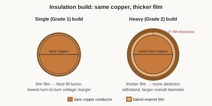
The trade-off is direct. Heavier build buys voltage withstand and abrasion resistance — more dielectric between turns, more film to survive the tension and scraping of winding — at the cost of fill factor. The overall diameter grows, so fewer turns fit a layer and fewer layers fit the window; a heavy-build wire needs a bigger window for the same turns. Single build maximises copper packing and is fine where inter-turn voltage is low and winding is gentle; heavy build is the sensible default for anything with meaningful inter-turn stress or rough handling; triple and quad are reserved for genuinely high-voltage windings. The bare-diameter table above plus the manufacturer’s build-diameter columns give the actual overall diameter that sets how many turns fit — the number the winding-window arithmetic actually needs.
5.4.2 Bondable (self-bonding) and coloured wire
Two specialty finishes deserve mention. Bondable or self-bonding wire carries, over its normal insulation, an extra thermoplastic bonding coat — a polyvinyl butyral or epoxy-type overcoat that is solid at room temperature but softens and flows when heated (by an oven, a current pulse through the finished coil, or a hot-air gun) or when wetted with a solvent such as denatured alcohol. As it cools or dries it fuses the turns into a single rigid mass. This is how a freestanding air-core coil — a self-supporting solenoid or voice coil with no bobbin or former left inside it — is made: wind it on a temporary mandrel, bond it, and slide the mandrel out. For anyone winding air-core RF coils, deflection yokes, or loudspeaker voice coils, self-bonding wire turns a floppy heap of turns into a solid component. Coloured enamel — pigment added to the film — is cosmetic and organisational: it lets a winder tell gauges or windings apart at a glance, or matches a manufacturer’s colour convention. The colour does not change the electrical or thermal behaviour.
5.5 Stripping and terminating
A coil is only as good as its two end connections, and the enamelled joint is a classic place for a coil to fail. The failure mode is the cold enamel joint: solder that has wetted the film but not the copper underneath, because the insulation was never fully removed. It looks connected, tests connected when new, and then goes intermittent or open under vibration and thermal cycling. Two honest approaches avoid it.
With solderable film (polyurethane family), the enamel is meant to be removed by the solder itself. Dip the lead into a solder pot hot enough (around 380–400 °C for polyurethane) and hold it a couple of seconds; the film decomposes, boils off, and the copper tins cleanly. A cool or brief dip leaves film behind and produces exactly the cold joint above — hence the pot must be genuinely hot and the dwell long enough, and very fine wire must not be left in so long that it dissolves. With non-solderable film (Formvar, polyester, PAI, polyimide), the film must be physically or chemically removed first: scraped with a blade, abraded with fine sandpaper or a fibreglass pencil, taken down on a rotating stripping wheel, burned/floated in a hotter pot, or dissolved with a proprietary stripping compound — then soldered like bare copper. Whichever the film, the rule is the same: verify that bright copper is exposed and wetted, not brown film. The mechanics of anchoring the start and finish turns, bringing out taps, and strain-relieving the leads belong to the winding-technique volume; this volume’s contribution is the warning that the film is engineered either to strip in the pot or to demand stripping — and mixing the two up is how coils go intermittent.
5.6 Skin effect and proximity effect
At DC and low frequency, current spreads uniformly across the conductor and the coil’s resistance is simply the DC resistance from the table. As frequency rises, that stops being true, and the effective AC resistance climbs — often dramatically — through two related mechanisms that between them govern why RF coils look the way they do and why Q collapses if the wire is chosen carelessly.
Skin effect is the tendency of alternating current to crowd toward the conductor’s surface. The changing magnetic field inside the wire induces eddy currents that oppose the flow in the centre and reinforce it near the surface, so the current density decays from the surface inward. The characteristic decay distance is the skin depth, δ — the depth at which the current density has fallen to 1/e (about 37%) of its surface value. Skin depth follows
δ = √( ρ / (π · f · μ) )
where ρ is resistivity, f frequency, and μ permeability. For copper the useful number to carry is δ ≈ 66 µm at 1 MHz, and because δ scales as 1/√f, it is ≈ 2.1 mm at 1 kHz, ≈ 0.66 mm at 10 kHz, ≈ 0.21 mm at 100 kHz, ≈ 21 µm at 10 MHz, and ≈ 6.6 µm at 100 MHz. (The Remington table’s “maximum frequency” column is the same idea from the other side: the frequency above which a given gauge’s radius exceeds a skin depth and skin effect begins to bite.)
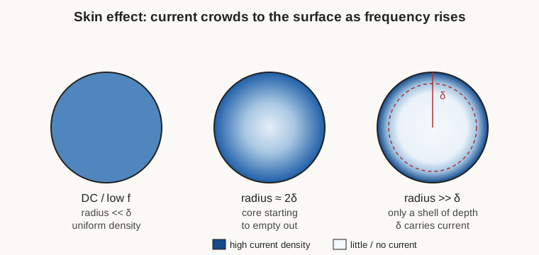
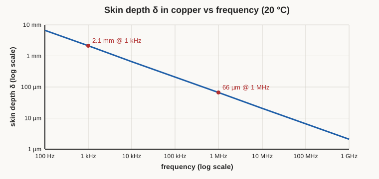
The practical rule that falls out of this: once the conductor radius exceeds a couple of skin depths, making the wire thicker barely lowers its AC resistance, because the extra copper sits in the dead centre where no current flows. A fat solid conductor at RF is mostly dead weight; the AC resistance is set by the surface area, not the volume. This is why RF work favours large-surface conductors — silver-plated tubing, flat strap, litz — over solid rod, and why simply “using thicker wire” for a high-Q RF coil is a beginner’s mistake.
Proximity effect is the second, sneakier mechanism, and it is the one that actually dominates in a multi-layer winding. Every turn sits in the magnetic field of its neighbours, and that external alternating field drives its own eddy currents in the conductor, crowding the current into a fraction of the wire’s cross-section — often worse than skin effect alone, and worst in the inner layers where the field from all the surrounding turns is strongest. Proximity effect is why a tightly packed multi-layer RF coil can have an AC resistance many times its DC value, and why RF coil geometries (spaced single layers, basket and honeycomb weaves — the subject of the coil-geometries volume) go to such lengths to keep turns out of one another’s fields. Skin effect and proximity effect together were introduced in the real-inductor volume as the reason a coil’s Q peaks and then falls with frequency; this volume supplies the wire-level cause and the numbers.
5.7 Litz wire
If the problem at high frequency is that current will only use a thin surface shell, the cure is obvious in hindsight: make the whole conductor out of surface. That is Litz wire — from the German Litzendraht, “braided wire.” Instead of one solid conductor, Litz is a bundle of many fine, individually enamel-insulated strands, twisted or woven together so that each strand, over the length of the cable, spends equal time on the outside and the inside of the bundle. Because each strand is thinner than a skin depth at the operating frequency, current fills it uniformly; and because the twisting transposes the strands, no strand is permanently buried where proximity effect would starve it. The bundle behaves, to a good approximation, as though its whole cross-section were surface — restoring a low AC resistance and a high Q that a solid wire of the same copper area could not touch.
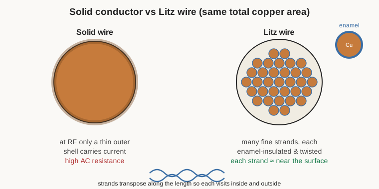
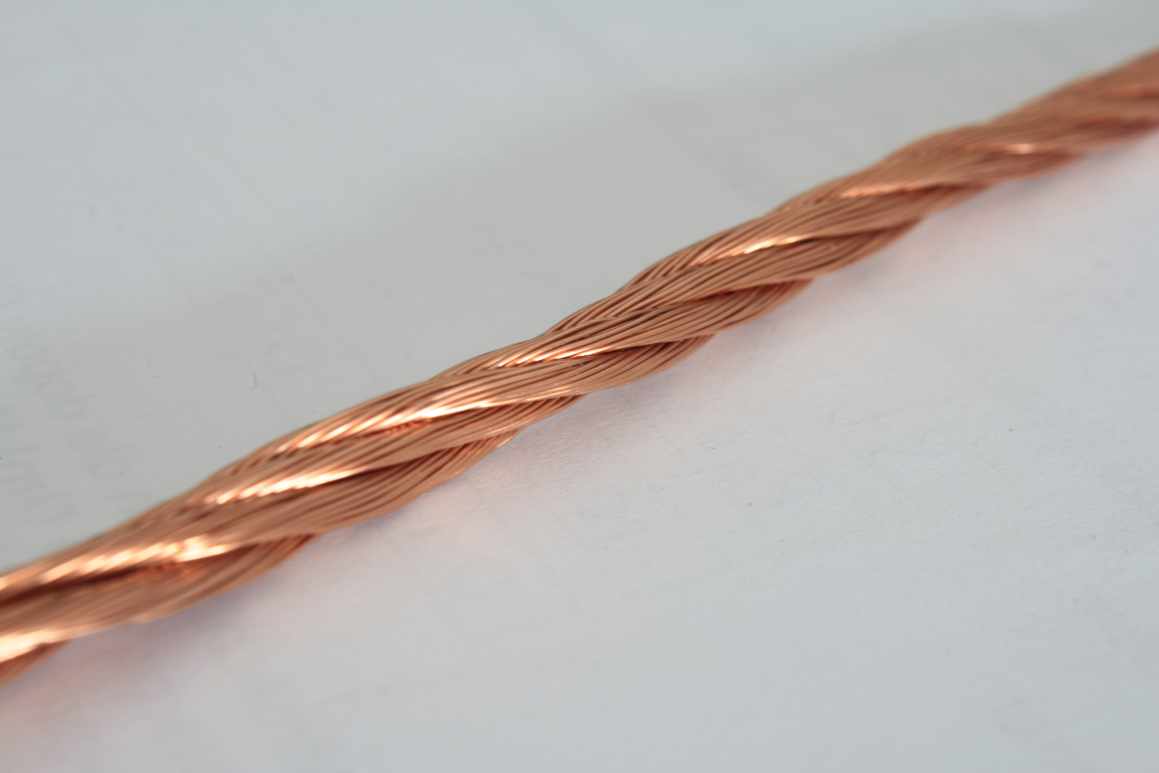
Litz is specified by strand count and strand gauge — “175 strands of AWG 40,” for example — with the strand gauge chosen fine enough (commonly AWG 30 to 48) that each strand is comfortably below a skin depth at the design frequency. The bundle may be bare (just the twisted strands, to be terminated by the user) or served — wrapped in a textile or film serving that holds it together and adds mechanical and voltage protection. Terminating Litz is its own small craft: every strand must be tinned, or the few strands that happen to reach the terminal carry all the current and the benefit evaporates — for solderable-enamel Litz this means a good hot solder pot; for non-solderable strands it means proper stripping.
The crucial engineering judgement is when Litz pays and when it is a waste of money and window. Litz earns its keep in the band roughly from tens of kilohertz up to a few megahertz — switch-mode and resonant power converters, induction heating, wireless-power coils, RFID, IF and antenna coils, and high-Q inductors and transformers in that range — where solid-wire skin and proximity losses are severe but the strands can still be made finer than a skin depth economically. Outside that window Litz is the wrong answer:
- At DC and low audio frequencies, there is no skin effect to fight. Litz just adds the insulation of hundreds of strands into the window (worse fill factor) and the cost of a complex cable, for no benefit. Solid wire wins.
- At high RF and VHF (well above a few megahertz), the required strand diameter drops below what is practical, the enamel between hundreds of strands adds capacitance and its own losses, and the bundle-level proximity effect and termination problems overwhelm the gain. Above roughly the low-MHz range, silver-plated solid wire or tubing, flat strap, or simply a well-spaced single-layer coil outperforms Litz.
In short, reach for Litz only when the skin/proximity loss at the actual operating frequency is bad enough to justify it — which is a real and common situation in power and RF magnetics from tens of kHz to a few MHz, and a beginner’s over-purchase almost everywhere else.
5.8 Fill factor and the winding window
The last wire-level reality every design collides with is that round wire cannot fill a rectangular window. Circles leave gaps. Even perfectly stacked, round conductors in square rows fill only about 78% of the area; nested in the tighter hexagonal (orthocyclic) arrangement they reach about 90% — and both figures are of the copper plus film, before the film, the interlayer insulation, the bobbin walls, and ordinary winding slack are subtracted.
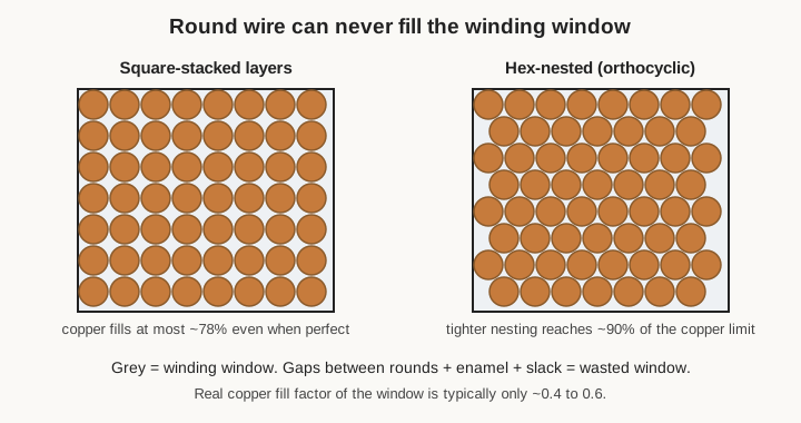
Engineers fold all of this into a single fill factor (or copper space factor): the fraction of the winding-window area that ends up as copper. For a real hand- or machine-wound coil that number is typically only 0.4 to 0.6 — a neat, careful machine winding of round enamelled wire pushes the top of that range; a hand-wound toroid or a coil with heavy build, thick layer insulation, and generous slack sits near the bottom. The consequences are concrete: the turns that fit a window are the bare-copper turns count times the fill factor, and the choices that raise voltage withstand — heavier build, interleaving insulation — cost fill factor and therefore turns. Gauge, build, and winding neatness together set how many turns fit and, with the core, the finished size of the component. The core-materials volume frames the window as a geometric budget; this volume supplies the exchange rate — copper area to turns — and the winding-technique volume supplies the skill that pushes a real winding toward the good end of the fill-factor range.
5.9 Choosing the wire, in one paragraph
Pulling the threads together, the winder’s decision procedure is short and repeatable. Pick the gauge from current and window fit: start from the circular-mils-per-ampere rule (roughly 500–1000 CM/A for a transformer), then check the resulting winding against its I²R heating and its allowed temperature rise, and against whether the required turns actually fit the window at a realistic fill factor — nudging the gauge up for cooler running or down to fit, and iterating. Pick the enamel class from temperature and solderability: a thermal class comfortably above the hottest the winding will run (Class 155/180 for ordinary work, 200 for hot motors and transformers, 220-plus for extreme service), and a solderable polyurethane-family film if the coil has many fine leads to terminate, accepting a stripped polyester/PAI/polyimide film only where the temperature or toughness demands it. Pick the build heavy by default, single only where fill factor is precious and inter-turn voltage is low, triple/quad only for genuine high-voltage windings. Reach for Litz only when skin and proximity effect at the operating frequency actually justify it — the tens-of-kHz-to-a-few-MHz band of power and RF magnetics — and never for DC, audio, or VHF-and-above work where it merely wastes copper, window, and money. And consider self-bonding wire whenever the goal is a freestanding air-core coil with no former left inside. Every one of these choices is a lever the later volumes — the winding machines, the winding technique, the design calculations, and the build-your-own projects — assume the reader now knows how to pull.
Comments (0)