Coils and Coil Winding · Volume 11
Specialty and Variable Inductors
11.1 When the plain coil is the wrong tool
Most of this deep dive has treated the inductor as a component that a designer wants to be as ideal as possible: high inductance for its size, low resistance, low loss, a self-resonance safely above the operating band. But a surprising number of the most useful magnetic parts in a modern circuit are the ones that break one of those rules on purpose. Some are meant to be lossy. Some are meant to change their inductance while the circuit runs. Some carry the working current in a way that lets its magnetic field cancel itself out. And some abandon the wound coil altogether and print the turns as copper on a board or a silicon die.
This volume is a tour of those specialists. Each earns its place by doing one job better than a general-purpose coil ever could, and each has a construction and a behaviour worth understanding before reaching for it. The through-line is that “inductor” is a broad word, and the parts bin marked L holds a menagerie. Where the geometry of the underlying windings is treated in full — the toroid, the common-mode winding, the air-cored solenoid — that is the province of the geometries volume; where these parts do their work in real filters, tuners, and supplies, that is the applications volume; the ferrite and powder materials they lean on are catalogued in the core-materials volume. Here the concern is the part itself: what it is, how it behaves, and where it wins.
11.2 The ferrite bead: an inductor that wants to be lossy
Start with the humblest and most misunderstood of the lot. A ferrite bead is nothing more than a small sleeve of lossy ferrite slipped over a wire, so that the wire passes once through the hole. It has no separate winding — the conductor is the single “turn” — and yet it is one of the most-placed components in consumer electronics, sitting on power rails, data lines, and connector pins by the billion.
The confusion starts with how it is specified. An ordinary inductor is rated in henries, because its job is to store energy in a magnetic field and give it back — to be reactive and low-loss. A ferrite bead is rated in ohms of impedance at a stated frequency, most commonly 100 MHz, because its job is the opposite: to dissipate high-frequency energy as heat rather than store it. A typical small chip bead might be specified as, say, 600 Ω at 100 MHz; a Fair-Rite material-43 bead of modest size sits nearer 50 Ω at that frequency. Quoting a bead in henries would be almost meaningless, because across the band where it does its work its behaviour is dominated not by reactance but by resistance.
11.2.1 The lossy region is the whole point
To see why, follow the bead’s impedance across frequency. At low frequencies the ferrite behaves like an ordinary small inductor: its impedance is mostly reactance, X = 2πfL, rising with frequency, and any energy it presents to a signal it largely reflects rather than absorbs. But ferrite is a lossy magnetic material, and as frequency climbs the material’s permeability becomes increasingly complex — it develops a large imaginary part that shows up in the circuit as a series resistance, R. Somewhere in the tens of megahertz the resistive term overtakes the reactive one; above that crossover the bead’s impedance is mostly R, and R stays high and broad well into the hundreds of megahertz.
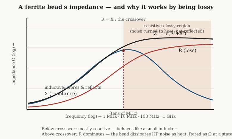
That resistive region is exactly what an EMI engineer wants. A reactive impedance reflects unwanted energy, which merely bounces it somewhere else in the system to cause trouble; a resistive impedance turns it into a trickle of heat and makes it go away. This is the fundamental distinction between a bead and an inductor. An inductor is designed to be low-loss — to have a high Q, to store and release energy cleanly. A bead is designed to be lossy — to have a low Q on purpose, so that a burst of high-frequency noise riding on a wire is damped rather than resonated. Placing a low-loss inductor where a bead belongs is a classic way to build an accidental resonant circuit that rings worse than the noise it was meant to cure.
11.2.2 Choosing and derating a bead
Because a bead is bought by its impedance curve, the selection is a matter of matching the curve to the problem. The engineer identifies the frequency band of the offending noise and picks a bead whose impedance peaks there. Different ferrite mixes place that peak in different places — a manganese-zinc-flavoured mix for tens of megahertz, a nickel-zinc mix for the hundreds — and the datasheet plots R, X, and total |Z| against frequency so the choice can be made by eye. Two numbers on the curve matter most: how high the impedance rises, and how broad the resistive hump is.
There is one derating that catches the unwary. The impedance curve on the datasheet is measured at essentially zero DC current. Run a real supply current through the bead and the ferrite is partially magnetised toward saturation, its permeability drops, and its impedance falls — often dramatically, so that a bead rated at 600 Ω might deliver only a fraction of that when carrying its rated DC bias. Manufacturers publish DC-bias derating curves for exactly this reason, and a bead chosen from its zero-current spec but installed on a heavily loaded rail may filter far less than the designer expected.
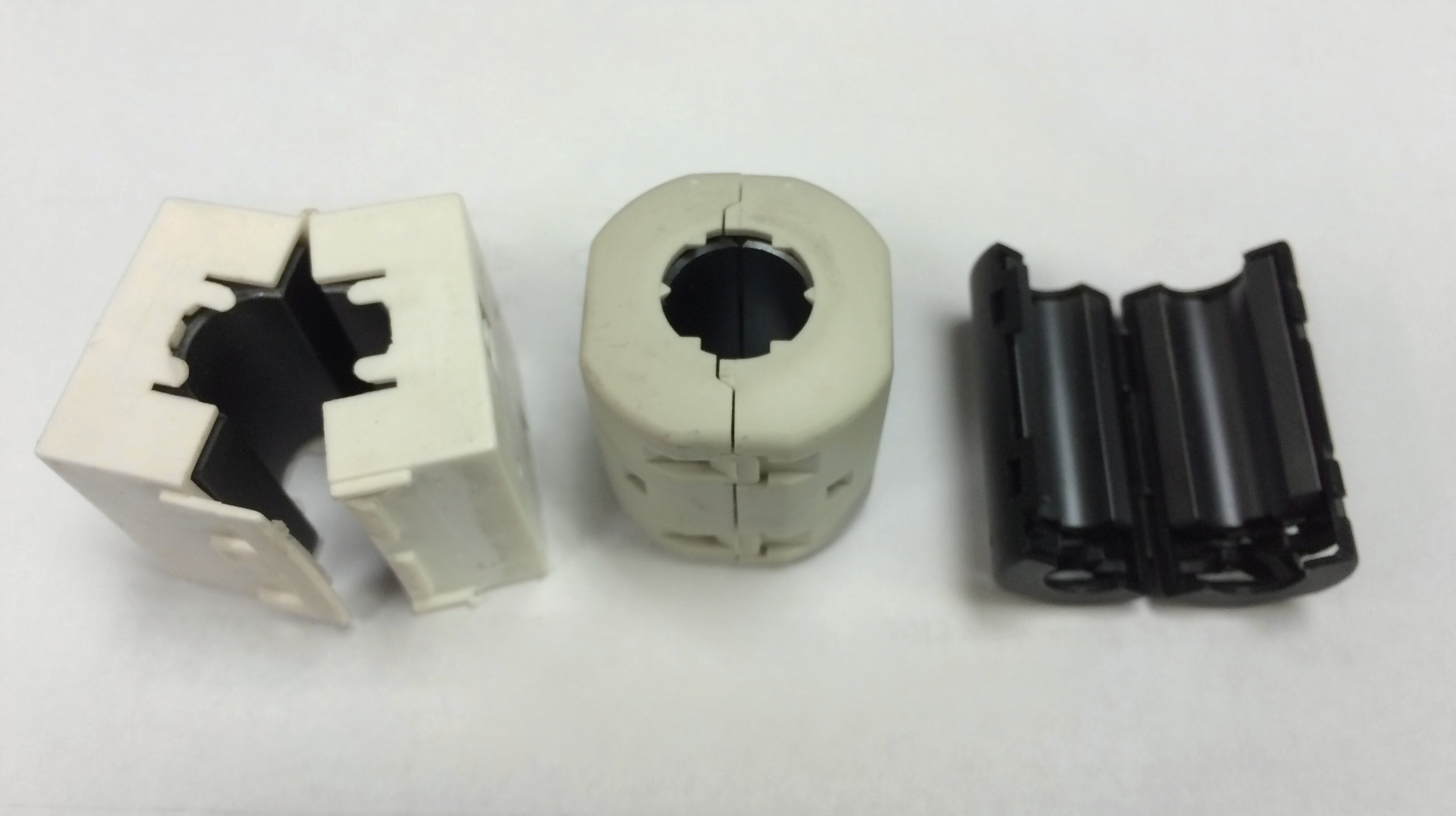
Beads come in three physical forms that share the same physics. Through-hole beads are a ferrite cylinder threaded on a component lead — the oldest style, still common on power pins. Chip beads are the surface-mount version, a monolithic block with metallised end terminations, indistinguishable at a glance from a chip resistor or capacitor and placed the same way by the same machines. And clamp-on cores are split ferrite sleeves in a hinged plastic shell that snap around a finished cable — the grey lump moulded onto a monitor or USB lead — letting an engineer add suppression after the fact without cutting the wire. Passing the cable through the core two or three times multiplies the low-frequency impedance, a cheap trick when a single pass is not enough. The use of beads and clamp-on cores in real EMI work belongs to the applications volume; the ferrite mixes that set their curves belong to the core-materials volume.
11.3 Common-mode chokes: filtering what both wires share
If the ferrite bead is the specialist for noise on a single wire, the common-mode choke is the specialist for noise shared across a pair of them. Its construction was set out with the other geometries — two identical windings on one core, wound so that the wanted signal or power current, flowing out on one wire and back on the other, drives the two windings in opposition — but the behaviour is worth restating here because it is where the part’s magic lives.
Split any current on a two-wire line into two components. The differential-mode current is the intended one: equal and opposite in the two conductors, the signal or the load current doing its job. The common-mode current is the parasite: equal currents flowing the same direction on both conductors, returning through ground and the surrounding structure, and it is common-mode current that radiates and couples as interference. A common-mode choke is built to be nearly invisible to the first and a brick wall to the second.
It manages this through flux cancellation. Wind the two conductors so their fields oppose for differential current, and the flux from the outbound wire cancels the flux from the returning wire almost perfectly. The core sees essentially no net flux from the differential current, which means two things at once: the choke presents almost no impedance to the wanted signal, and — crucially — the differential current does not magnetise the core, so it cannot saturate it. A single choke carrying the full load current would need a core big enough not to saturate on that current; a current-compensated common-mode choke sidesteps the problem entirely, because as far as the core is concerned the load current is not there. Its current rating is set by the wire gauge — how much copper it takes to carry the load without overheating — not by any saturation limit. This is why the same small core can handle a startling amount of line current.
For common-mode current the trick runs backward. Both windings push flux the same way around the core, the fluxes add, and the choke presents its full common-mode inductance — a high impedance that chokes the interference. On power lines these are the current-compensated chokes in the mains filter, tens of amps of load current passing untouched while common-mode trash is blocked; on data lines they are the small chokes on USB, Ethernet, and HDMI pairs, sized to peak where those interfaces radiate.
Selection follows the same logic as the bead: pick the choke whose common-mode impedance peaks where the emissions are worst — tens of megahertz for a long power harness, a hundred megahertz or more for a fast data port. And the same saturation caveat applies in reverse: while the differential current cannot saturate the core, any imbalance in the line — a real common-mode current, or an asymmetry in the load — does drive net flux, so a choke pushed past its common-mode rating saturates, loses impedance, and quietly stops filtering. The geometry that makes all this work, including the bifilar and sectioned winding styles, is detailed in the geometries volume.
11.4 Saturable reactors and magnetic amplifiers: controlling power with a whisper of DC
The next specialist turns the inductor’s greatest weakness into a control mechanism. Every core has a saturation ceiling; drive it toward that ceiling and its permeability collapses, taking the inductance of any winding on it down with it. A saturable reactor exploits this deliberately. It carries two windings on one core: a main (AC) winding in series with the load, and a separate control winding fed with direct current. The DC control current sets how far the core is already biased toward saturation, and that bias sets the AC inductance the main winding presents.
With no control current the core is unsaturated, the main winding shows a high inductance, its reactance is large, and it chokes the AC — little power reaches the load. Push DC through the control winding and the core moves toward saturation; the main winding’s incremental permeability, and with it its inductance, falls; its reactance drops; and more AC power flows. Drive the core hard into saturation and the main winding is nearly a short length of wire, passing the AC almost unimpeded. A small, low-power DC signal in the control winding thus governs a large flow of AC power in the main winding — the reactor is, in effect, a variable inductor commanded by a knob made of current. Because the control winding does its work by magnetising the core rather than by carrying the load, it commonly has many more turns than the main winding, trading current for the ampere-turns needed to bias the core.
Wire the control action to amplify, and the same device becomes a magnetic amplifier, or “mag amp”: a small change in DC control power produces a large change in delivered AC power, with power gain and no moving parts, no tubes, and no semiconductors. This is not a historical curiosity dressed up as one. In the mid-twentieth century, before power transistors, mag amps regulated everything from ship steering gear to aircraft electrics and welding sets, prized for a ruggedness that vacuum tubes could not match — they shrugged off overloads, vibration, radiation, and temperature swings that would kill anything more delicate, and some of that gear is still running.
The principle did not retire when transistors arrived; it migrated. In modern switched-mode power supplies, a mag-amp post-regulator is a standard way to tightly regulate a secondary output on a multi-output transformer. A small saturable core in series with the secondary is driven each switching cycle from a saturated (conducting) state, and a control circuit adjusts a DC bias to delay when it saturates, effectively chopping each pulse to the width that holds the output in regulation — a fast, efficient magnetic switch doing the fine trimming that a shared primary controller cannot. The core material for a mag amp is chosen for a very square hysteresis loop, so the transition from blocking to conducting is sharp; those square-loop materials are surveyed in the core-materials volume.
11.5 The tuning family: variable inductors
Where the saturable reactor varies inductance electrically, the classic variable inductors vary it mechanically — a slug that screws in, a coil that rotates, a contact that rolls. All three exist to tune a circuit, and each dominates a different corner of the tuning problem.
11.5.1 Slug and permeability tuning
The most common adjustable inductor hides inside almost every old radio: a coil with a threaded magnetic or metallic slug that screws in and out of its bore. Moving the slug changes the effective permeability seen by the winding, and so changes the inductance, without touching a single turn. It is the working mechanism of the adjustable RF coil, the alignment “can,” and the intermediate-frequency (IF) transformer.
The direction of the change depends entirely on what the slug is made of, and the two cases are worth getting straight because they are exact opposites.
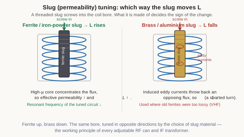
A ferrite or iron-powder slug is a magnetic material with permeability well above that of air. Screwing it into the bore adds high-permeability material to the coil’s magnetic path, concentrates the flux, raises the effective permeability, and so raises the inductance — moving the slug in lowers the resonant frequency of the tuned circuit it sits in. This is the usual arrangement, because ferrite slugs are efficient, stable, and give a large, smooth tuning range.
A brass or aluminium slug does the reverse. These metals are non-magnetic, so they add no permeability; instead the coil’s alternating field induces circulating eddy currents in the metal, and those currents, by Lenz’s law, set up a flux that opposes the coil’s own. The slug behaves like a shorted single turn coupled into the coil, and its back-reaction lowers the inductance — moving a brass slug in raises the resonant frequency. Brass tuning was the tool of choice at VHF and above in the era when the available ferrite and iron-powder mixes were simply too lossy to use at those frequencies; the small eddy-current loss of a good conductor beat the magnetic loss of a poor ferrite. The mnemonic is worth memorising: ferrite up, brass down.
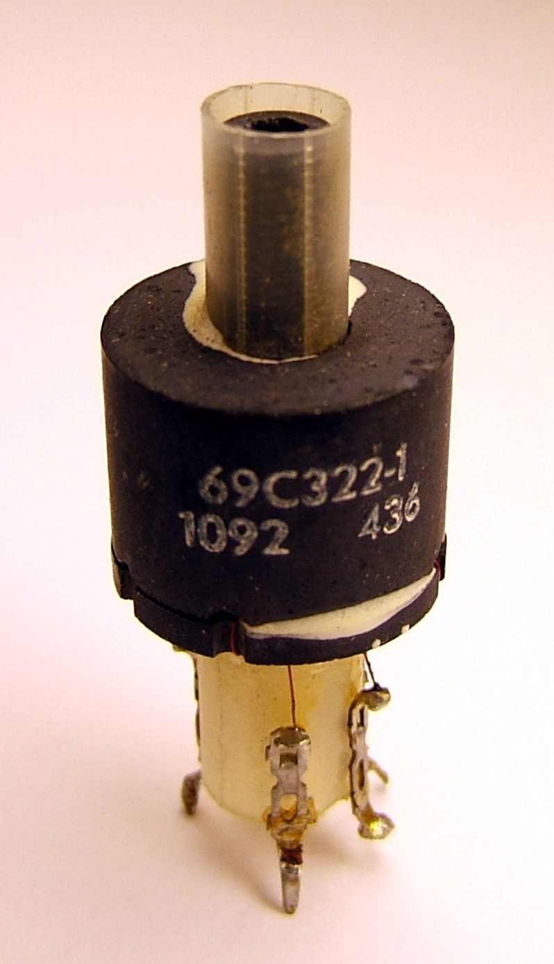
Two practical notes follow from the mechanism. First, the slug must be adjusted with a non-metallic trimming tool — a metal screwdriver left in the bore is itself an eddy-current slug and detunes the very thing being set, and can snap the brittle ferrite besides. Second, because the slug’s position sets a critical alignment, production IF transformers use a wax or thread-locking compound to keep the slug from wandering with vibration and age; freeing a seized decades-old slug without cracking it is a familiar restorer’s ordeal. Measuring a slug-tuned coil’s inductance versus slug position is a job for the methods in the measurement volume.
11.5.2 The variometer
Where a slug tunes by permeability, a variometer tunes by mutual coupling. It is two coils wired in series, one nested inside the other, with the inner coil mounted on a pivot so it can rotate relative to the fixed outer one. Total inductance of two series-connected coupled coils is Ltotal = L₁ + L₂ ± 2M, where M is the mutual inductance between them — and M depends on their relative orientation. Rotate the inner coil so its field aligns with the outer coil’s and the mutual term adds at full strength, giving maximum inductance; rotate it the other way and M subtracts, dropping the inductance to a minimum. Everything in between is available continuously by turning the shaft.
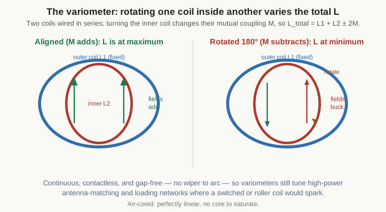
The variometer’s virtues are that it is continuous, contactless, and gap-free. There is no sliding contact to wear, pit, or arc, and no switched taps to jump between values, so the adjustment is smooth and the part can handle real power. It was the tuning element of choice in early-twentieth-century radio — spark transmitters and crystal-set receivers alike — and it never fully left: variometers still tune antenna-matching and loading networks, and turn up in the loading coils of physically short transmitting antennas where the required inductance must be trimmed to resonance under high circulating current. Being air-cored, a variometer is perfectly linear and has nothing to saturate, which is exactly why it survives in high-power service where a ferrite would cook. Its role in tuning and matching is developed in the applications volume.
11.5.3 Roller inductors and tapped coils
For the highest-power tuning of all — the antenna tuner behind a kilowatt transmitter — the tool is the roller inductor. It is a large air-cored solenoid with a conductive wheel or roller riding against the bare wire of the winding, carried on a rail that runs the length of the coil. Turning the coil’s shaft screws the roller along the helix like a nut on a thread, and the roller taps off the winding at a continuously variable number of turns, so the inductance can be set anywhere from a fraction of the whole down toward zero. A representative high-power roller might range from a couple of hundred nanohenries up to some tens of microhenries with a quality factor in the many hundreds, and tuners built around them handle several kilowatts.
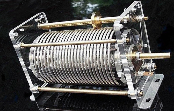
The roller’s advantage over a switched, tapped coil is that its adjustment is continuous: it can find the exact inductance for a perfect match, where a tapped coil can only offer the discrete values at its taps. The trade is mechanical complexity and a sliding contact that must carry RF current without arcing — the reason high-current tuners specify silver-plated wire and a firmly sprung roller. The simpler alternative, the tapped coil, brings out connections at chosen turns and selects among them with a switch. It gives up fine resolution but is rugged, cheap, and perfectly suited to band switching, where a circuit needs to jump between a handful of known inductances rather than sweep continuously — the band switch on a transmitter or a tube-amplifier tank circuit is exactly this. Winding a coil with clean, mechanically sound taps is a technique covered in the winding-practice volume.
11.6 Chip, molded, and shielded inductors: the surface-mount families
Everything so far has been either exotic or adjustable. The workhorses of modern assembly are neither: they are small, fixed, surface-mount inductors picked and placed by the reel. But even here the choices are real, because “SMD inductor” spans parts optimised for utterly different jobs.
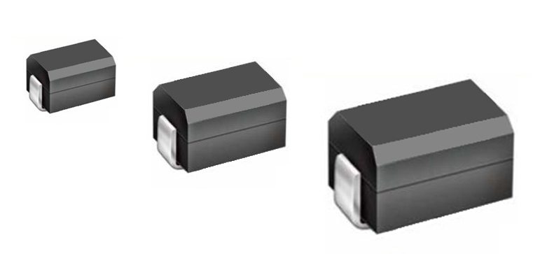
The wire-wound chip inductor is the most literal miniaturisation of a coil: fine wire wound on a tiny ceramic or ferrite core, terminated at the ends for reflow soldering. A ceramic (air-cored) core gives a low but extremely stable and low-loss inductance for RF work; a ferrite core gives more inductance in the same footprint at the cost of some loss and a saturation limit. Because the conductor can be relatively thick copper, wire-wound chips reach the highest Q of the small fixed inductors, which is why they populate matching networks, filters, and oscillator tanks where loss directly costs performance.
For power — the inductor in a buck or boost converter — the priorities shift from Q to current handling, and the field splits between two constructions. Shielded drum (or “drum-core”) inductors wind the coil on a ferrite bobbin, then cap it with a ferrite sleeve or plate that closes the magnetic path and contains the stray field, keeping it from coupling into neighbouring circuitry. Molded metal-composite inductors take a different route: the coil is embedded in a pressed slurry of insulated soft-magnetic metal powder and moulded into a solid block, so the winding and its magnetically shielding “core” are one piece.
The two behave differently at the edge of their rating, and the difference is instructive. A ferrite core saturates hard: below its saturation current the inductance is nearly constant, then it collapses over a narrow current range, and a transient that crosses that knee can drop the inductance almost instantly and let current run away. A metal-composite core saturates soft: because its permeability comes from a distributed gap between insulated grains, its inductance rolls off gradually and continuously as current rises, giving warning and graceful degradation rather than a cliff. The composite’s higher saturation flux density also lets it carry a higher saturation current in a smaller package. The price is that composite material has lower permeability than ferrite, so a target inductance needs more turns, which raises the DC resistance somewhat, and its core loss can be higher — the ferrite-versus-powder trade-offs surveyed in the core-materials volume, here decided in favour of ruggedness and size. The two numbers that arbitrate a power-inductor choice are its DCR — the DC winding resistance, which sets the conduction loss — and its Isat — the saturation current, which must sit comfortably above the peak current the converter ever demands. Shielded parts are preferred wherever a stray field would misbehave; the closed magnetic path is what makes them quiet neighbours.
11.7 Multilayer and thin-film chip inductors
Below the wire-wound chip in size and cost sits a family with no wire at all. A multilayer chip inductor is built the way a multilayer ceramic capacitor is built: alternating printed layers of conductor and ceramic, co-fired into a monolithic block, with the conductor traces stacked and interconnected so that they spiral into a coil buried inside the part. There is no winding to wind and no core to insert; the inductor is grown as a solid ceramic brick.
The virtues are miniaturisation, low cost, and mechanical toughness — the same reasons multilayer ceramic capacitors dominate their category. The catch is Q: a multilayer chip’s printed conductors are thin and its ceramic is lossy compared with a wound coil’s copper and air, so its quality factor is lower than a wire-wound chip of the same value, and its current handling is modest. That is often an acceptable trade, because a multilayer part balances inductance tolerance, size, rated current, and price well enough for the great mass of RF bypass, bias-feed, and coupling duties where a merely adequate inductor is fine. It is the wire-wound chip’s cheaper, humbler sibling: reach for wire-wound when Q or current matters, multilayer when size, cost, and count dominate.
At the top of the frequency range, precision passes to the thin-film chip inductor. Here the spiral is patterned by photolithography — sputtered or plated metal traces defined to micron tolerances on a smooth ceramic substrate — the same toolset that makes integrated circuits. The photolithographic precision buys extremely tight inductance tolerance and very repeatable, well-controlled behaviour up into the microwave region, which is why thin-film parts populate the front ends of cellular, Wi-Fi, and radar hardware where a matching network’s inductance must be exact and its self-resonance far away. The values are small — thin-film shines at the low-nanohenry to sub-nanohenry inductances that microwave circuits actually use — but within that range nothing else is as precise. Verifying such small inductances and their high self-resonant frequencies is a measurement challenge in its own right, addressed in the measurement volume.
11.8 Planar, PCB, and integrated inductors
The last step in the progression is to stop making a separate component at all and print the inductor into the board or the chip. A planar inductor replaces the wound coil with a flat spiral of copper — a trace that spirals inward on one layer, with the inner end brought out on a second layer through a via that passes under the spiral. The turns are conductor width and spacing on a substrate rather than wire on a former, and the whole “coil” is etched at the same time as everything else around it.
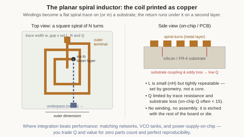
This appears at two very different scales. On a printed circuit board, planar magnetics build high-density power components: the spiral windings of a converter’s transformer or inductor are etched into the copper layers of a multilayer PCB, sometimes with a ferrite core clamped through a slot in the board, giving a flat, manufacturable, repeatable magnetic part with no hand-winding. The technique trades winding freedom for reproducibility and low profile, and it dominates dense, high-frequency power supplies where a wound transformer would be too tall and too variable. Smaller PCB spiral inductors — just a spiral trace, no core — serve as RF inductors and matching elements where a few tens of nanohenries etched into the board is cheaper and more repeatable than a placed part.
At the smallest scale, the same spiral is fabricated on the silicon die itself: the on-chip spiral inductor of a radio-frequency integrated circuit, patterned in the chip’s top metal layers alongside the transistors it resonates with. These are the tuning elements of on-chip oscillators, low-noise amplifiers, and matching networks, and their appeal is total integration — no external part, no bond wire, no placement, and geometry-defined values that repeat perfectly from die to die.
What they give up is performance, and honestly so. An on-chip spiral’s inductance is small and its footprint large: a ten-nanohenry spiral can occupy a few hundred microns on a side, an enormous area by IC standards. Worse, it sits close over a conductive silicon substrate that steals energy through capacitive coupling and induced eddy currents, so its Q is low — often below fifteen, sometimes single digits — where a discrete coil would offer hundreds, and its self-resonant frequency, though high, is finite. The designer accepts a mediocre inductor because it is free in parts and placement and perfectly reproducible, and then designs the circuit around its limits. The predictability is the selling point: the inductance is set by geometry a photomask controls exactly, even if the Q is set by physics the designer cannot escape. The low but calculable L and the Q ceiling of these integrated coils are precisely the parameters the measurement volume shows how to extract.
11.9 When to reach for a specialty part
The menagerie sorts cleanly once each animal’s one job is clear. For high-frequency noise on a single wire, reach for a ferrite bead — bought in ohms, prized for being lossy, sized by matching its impedance hump to the offending band and derated for DC bias. For noise shared across a pair of conductors, reach for a common-mode choke, which passes the load current untouched because that current’s flux cancels in the core, and blocks common-mode trash where its impedance peaks. To control large AC power with a small DC signal and no moving parts, reach for a saturable reactor or magnetic amplifier, still trimming secondary rails inside switched-mode supplies long after it left the machine room.
To tune, choose by power and resolution: a slug for compact, low-power RF alignment (ferrite up, brass down); a variometer for continuous, contact-free, high-power tuning that cannot arc; a roller inductor for continuously variable inductance in a kilowatt antenna tuner; a tapped coil and switch for jumping between a few known bands. For compact fixed inductance, let the job decide: a wire-wound chip when Q or current is precious, a multilayer chip when size, cost, and count rule, a thin-film chip when microwave precision is the point, and a molded or shielded power inductor — soft-saturating composite or quiet shielded drum — for the converter, chosen on DCR and Isat. And when the goal is integration above all, print the coil: a planar spiral on the board for dense power or repeatable RF, an on-chip spiral on the die for a matching network that must cost nothing and repeat forever, accepting the low Q as the toll for having no part to place at all.
The plain coil of the first volumes remains the default. But a designer who knows this catalogue rarely fights a general-purpose inductor into a job it was never meant for — there is almost always a specialist that was.
Comments (0)