Coils and Coil Winding · Volume 10
Where Inductors Are Used
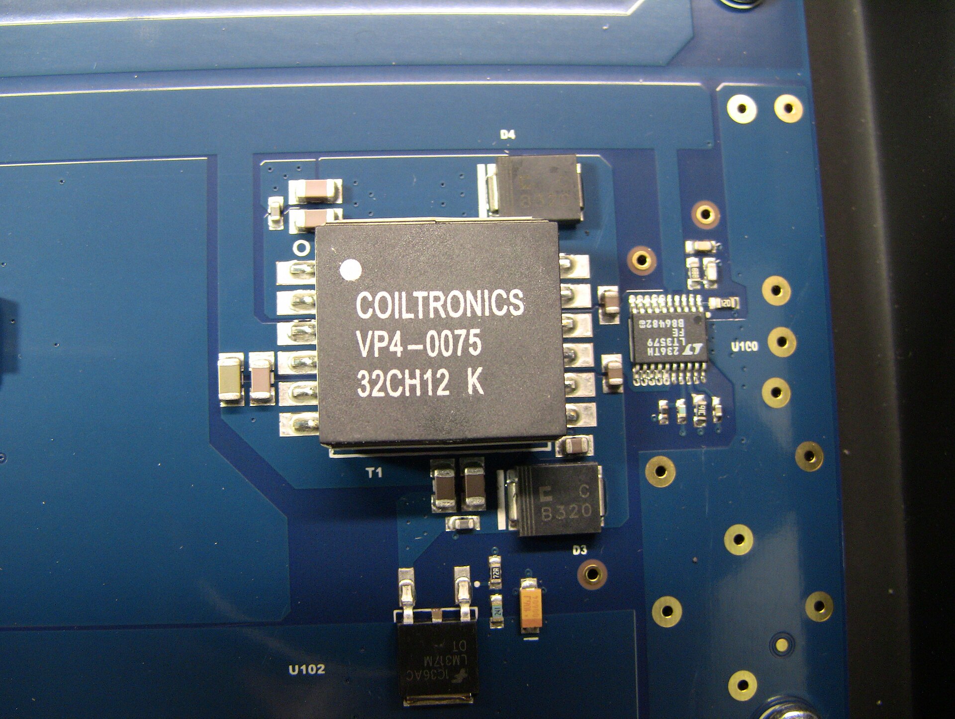
10.1 The same lump of wire, a dozen different jobs
Every previous volume has treated the inductor as an object to be understood — a field wound onto a former, a set of parasitics, a core material, a target value to be calculated. This volume turns the telescope around and asks the only question a working engineer actually cares about: what is the thing for? The answer is unusually broad. A resistor dissipates, a capacitor stores charge in a field between plates, and each does essentially one thing in a dozen dressings. An inductor stores energy in a magnetic field, opposes changes in current, and presents a reactance that climbs with frequency — three plain facts — and out of those three facts fall a startling range of jobs, from picking one radio station out of the ether to keeping a laptop charger from spraying hash across the FM band.
What follows is a tour of those jobs, one application domain at a time. Each section answers three questions in order: what circuit role the inductor plays, why an inductor and not some cheaper or smaller alternative, and what the part actually looks like — the value it takes, whether it is a hand-wound coil or a mass-produced chip, and which of its non-ideal traits from the earlier volumes suddenly becomes the thing that matters. The physics is all behind us; this is where it earns its keep.
10.2 Resonant and tuned circuits: the heart of radio
Pair an inductor with a capacitor and something new appears that neither has alone: a resonant frequency, a single frequency at which the two reactances cancel and the pair behaves in a way that defines an entire discipline. This is the LC tank circuit, and it is the reason radio exists in a recognisable form.
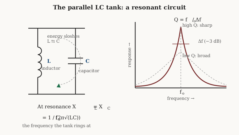
The mechanism is a slow-motion oscillation. Charge the capacitor and let it discharge through the coil; the current builds a magnetic field, and when the capacitor is empty the collapsing field drives the current on, recharging the capacitor with the opposite polarity. Energy sloshes between the electric field of the capacitor and the magnetic field of the coil, back and forth, at a rate set entirely by the two values. That rate is the resonant frequency, and it comes straight from setting the inductive reactance equal to the capacitive one:
f₀ = 1 / (2π√(LC))
The relationship between reactance and frequency was the foundational fact of the opening volume; here it does real work. At resonance the circuit’s response peaks sharply, and how sharply is governed by the Q factor — the ratio of energy stored to energy lost per cycle. A parallel tank’s selectivity follows directly: the −3 dB bandwidth is Δf = f₀*/Q*, so a Q of 100 at 1 MHz gives a bandwidth of 10 kHz, tight enough to separate adjacent stations, while a Q of 10 smears across 100 kHz and lets neighbours bleed through. Selectivity — the ability to accept one frequency and reject its neighbours — is Q made audible.
This is precisely why coil quality matters more in RF work than anywhere else in electronics. The capacitor in a tank is nearly lossless; the coil is not, and the coil’s losses — DC resistance swollen by skin effect, core loss, radiation, dielectric loss in the former — set the Q and therefore the selectivity of the whole circuit. An engineer who wants a sharp filter cannot buy it from a chip inductor with a Q of 20; the tuned front end of a good receiver wants a Q of 100 to 200 or better, and that comes only from a properly built coil. Hence the RF coil-maker’s whole toolkit, unpacked in the geometries and wire volumes: single-layer solenoids wound on low-loss formers to keep self-capacitance and dielectric loss down, Litz wire to beat skin effect at frequencies below a few megahertz, and honeycomb or basket weaves that space the turns to suppress the proximity effect and self-capacitance that would otherwise wreck Q. The reason those winding crafts survive is that no printed or moulded part matches a well-wound air-core coil for Q.
10.2.1 Tuning, oscillators, filters, and matching
The tank is the seed of four RF sub-jobs. Tuning a receiver means moving f₀ across a band, done historically by a variable capacitor swinging against a fixed coil, or by a fixed capacitor against a slug-tuned coil whose ferrite core screws in and out to vary the inductance — the mechanism the specialty volume takes up in detail. Oscillators hang an amplifier around a tank so that the circuit sustains its own ringing at f₀; the LC pair is the frequency-determining element, and the coil’s stability with temperature decides how far the transmitter drifts. Filters cascade tanks to pass or reject bands with skirts far steeper than any single RC stage — the intermediate-frequency strip of a superheterodyne receiver is a chain of coupled LC resonators, and every one of them is a wound coil paired with a capacitor.
The fourth job is impedance matching. An antenna, a power amplifier, and the cable between them each present their own impedance, and power transfers cleanly only when they are matched. L-networks, pi-networks and T-networks built from a coil and one or two capacitors transform one impedance to another at a chosen frequency, and the antenna tuner in every transmitter is exactly this — a variable coil and variable capacitor juggled until the amplifier sees the load it wants. A close cousin is the trap: a parallel LC tuned to one specific frequency, which at that frequency presents a very high impedance and blocks it while passing everything else. Traps let a multi-band antenna behave as several antennas in one, and let a receiver notch out a single interfering carrier. In all four jobs the coil is a wound part chosen for Q and stability, not a commodity chip.
10.2.2 Antenna loading coils
A short antenna is an electrically awkward thing: shorter than the natural resonant length for its frequency, it looks capacitive to the transmitter and radiates poorly. The fix is to add the missing inductance with a loading coil, wound into the base or the middle of the whip, which cancels the antenna’s capacitive reactance and brings it back to resonance.
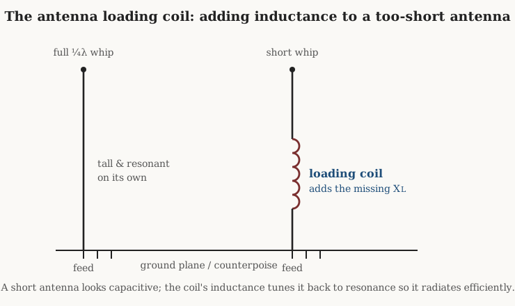
This is the fat coil at the base of a mobile HF whip, the reason a 2-metre handheld’s rubber-duck antenna works at all despite being a fraction of a full quarter-wave, and — in a historical guise — the coils Pupin and Campbell inserted along early telephone lines to flatten their frequency response. It is a wound coil chosen for Q, because a lossy loading coil throws away as heat the very power the short antenna was struggling to radiate.
10.3 Power conversion: the inductor as an energy bucket
If RF is where the inductor’s reactance is exploited, switch-mode power conversion is where its energy storage is. The switching regulator that steps a laptop’s 20 volts down to the 1 volt a processor core wants, or a phone’s 3.7-volt cell up to the 5 volts a USB port expects, does it by shuttling energy through an inductor in packets, thousands or millions of times a second. The inductor is not incidental here; it is the component that makes the whole efficient conversion possible.
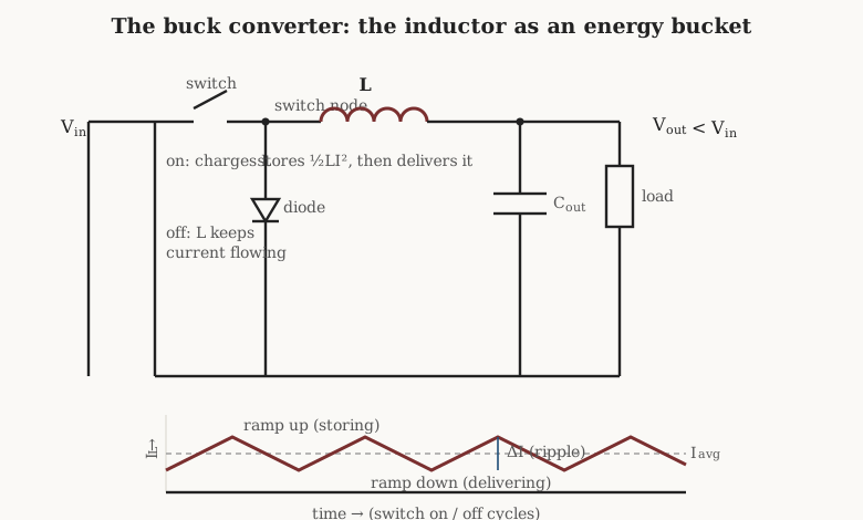
Follow one cycle of the buck (step-down) converter. The switch closes and connects the input across the inductor; current ramps up linearly — an inductor forces current to change gradually, so the rate is set by the applied volts and the inductance, dI/dt = V/L — storing energy in the magnetic field as ½LI². The switch then opens, and the inductor does the thing that makes it magical: its collapsing field keeps the current flowing in the same direction, now looping through a diode (or a second switch) and pushing that stored energy into the output capacitor and load. Over many cycles the output settles at a voltage set by the fraction of time the switch is on. The boost converter rearranges the same three parts to pump energy up to a higher voltage; the buck-boost and its isolated cousins juggle them for either. In every topology the inductor is the bucket that carries energy across from input to output in controlled scoops.
Why an inductor rather than, say, a resistor divider or a linear regulator? Because storing and releasing energy is nearly lossless, while dropping voltage across a resistance burns the difference as heat. A linear regulator making 1 volt from 20 throws away 95 percent of the power; a switcher built around an inductor delivers 90 percent or more of it, and that is the entire reason the component exists in every phone, laptop, and LED driver on Earth.
10.3.1 What binds the design: ripple, Isat, and Irms
The inductor’s current is not steady — it is a triangle wave, ramping up while the switch is on and down while it is off, riding on top of the DC output current. The peak-to-peak height of that triangle is the ripple current, ΔI, and choosing the inductance is largely a negotiation over it. A common rule of thumb across the switching-supply literature sets the ripple to roughly 20 to 40 percent of the maximum output current, with 30 percent the usual compromise; a bigger inductor gives smaller ripple (smoother current, less output filtering needed) but is physically larger and slower to respond, while a smaller one is compact and nimble but demands a bigger output capacitor to mop up the ripple.
Two current ratings from the real-inductor volume both come due here, and the design must clear both. The saturation current, Isat, must exceed the peak of the triangle — the average current plus half the ripple — or the core saturates at the top of each cycle, the inductance collapses, and the current spikes into whatever switch is conducting. Prudent designers rate Isat above the converter’s current-limit threshold, not merely its normal peak, so a fault does not saturate the part. The RMS current, Irms, is the thermal limit, driven by the copper’s I²R heating; the RMS of the triangle is very nearly the DC output current, and Irms governs how hot the part runs. A power inductor datasheet gives both, at a stated inductance-drop percentage and a stated temperature rise respectively, and a good design has margin on each.
These twin demands are exactly why power inductors are built the way they are: on gapped ferrite or distributed-gap powder cores rather than ungapped high-permeability material. The gap — whether a physical slot milled into a ferrite E-core or the microscopic gaps between insulated grains in a powdered-iron toroid — stores most of the energy in the gap rather than the iron, and air cannot saturate, so it buys the high Isat that a DC-biased energy-storage inductor needs. The core and design volumes work the gapping arithmetic; the point here is that the application dictates the construction.
The physical part is usually a shielded drum or moulded inductor — a bobbin winding buried inside a magnetic shell that contains the field so the switcher does not spray magnetic noise across the board. Values run from well under a microhenry in megahertz-class point-of-load converters up to hundreds of microhenries in low-frequency or high-voltage supplies; higher switching frequency lets the inductance shrink, which is the whole reason converter frequencies have climbed into the megahertz. Most are mass-produced surface-mount chips. But two power jobs still call for larger wound parts: the output filter choke in higher-power or off-line supplies, and the power-factor-correction (PFC) choke at a mains-fed supply’s front end, which shapes the input current to follow the line voltage and can be a substantial gapped-ferrite or powder-core component carrying real current. A brief mention is owed to the coupled inductor, two windings on one core used in SEPIC and multi-output converters — a half-step toward the transformer, and a reminder that the coming transformers dive is really the study of what happens when two coils share a field on purpose.
10.4 Filtering and energy smoothing
Step back from switching converters to the older, quieter job the inductor has always done in power supplies: smoothing. A rectifier turns AC into a lumpy, pulsing DC full of ripple at twice the line frequency. An inductor placed in series with that pulsing current resists the change in current — that is its defining property — and so it passes the DC average while opposing the AC ripple, ironing the lumps flat.
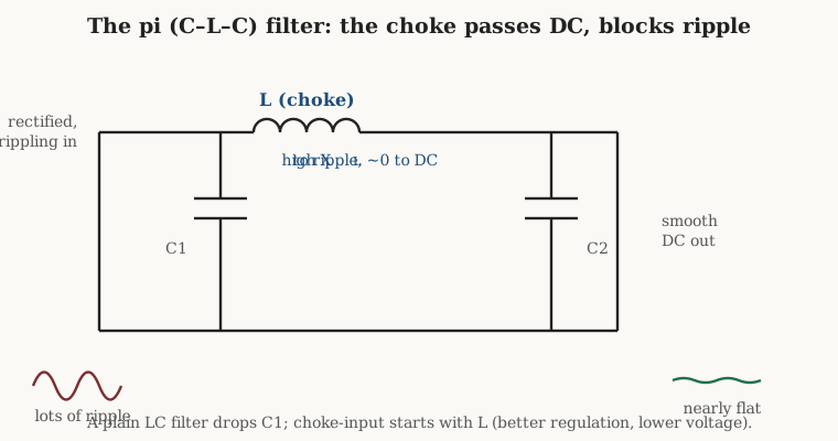
The workhorse arrangements are the LC filter — a series choke followed by a shunt capacitor — and the pi filter, a capacitor, then the choke, then another capacitor, drawn like the Greek letter π. The choke blocks ripple while passing DC; the capacitors bypass whatever ripple survives to ground. There is a classic and instructive fork in how the filter begins. A capacitor-input filter puts a capacitor first, right on the rectifier, and delivers a high output voltage (approaching the peak of the AC) but poor regulation — the voltage sags as load increases. A choke-input filter puts the inductor first; the output voltage is lower (approaching the average, about 0.9 of the RMS) but the regulation is excellent and the current draw from the transformer is smooth and continuous rather than drawn in hard peaks. The trade is a staple of the old ARRL and radio-engineering handbooks: choke-input for a stiff, well-regulated supply, capacitor-input for a high-voltage, light-load one.
The chokes for this job — often called DC chokes or filter reactors — are wound for high inductance at low frequency, historically several henries in a valve-amplifier or transmitter supply, on laminated silicon-steel cores because the frequency is low enough that laminations beat ferrite on cost and saturation flux. A swinging choke is a deliberately under-designed variant whose inductance falls as current rises, keeping it high at light load where it is most needed. This is a laminated, bobbin-wound part, closer kin to a small transformer than to a chip inductor, and it is one of the places the winding craft of the earlier volumes still turns out physical hardware. The same principle scales down to signal work: a series inductor plus shunt capacitor is a low-pass filter, and the reactance-versus-frequency behaviour that makes a choke smooth ripple is the same behaviour that makes an LC network a filter with a defined cutoff.
10.5 EMI and noise suppression
Electronics does not only make signals; it makes mess. Every switching edge, every clock, every motor commutation flings energy across the spectrum, and regulations plus plain functionality demand that the mess be contained. A large fraction of the coils in a modern product are there not to do anything with a signal but to stop an unwanted one — and the inductor’s frequency-dependent impedance is exactly the tool for it, because it can be arranged to ignore the wanted low-frequency current while presenting a wall to high-frequency noise.
The first distinction to draw is between two kinds of noise on a pair of wires. Differential-mode noise flows out on one conductor and back on the other, in antiphase — the same path the wanted signal or power takes. Common-mode noise flows in the same direction on both conductors at once, returning through ground or through stray capacitance to the surroundings; it is the dominant culprit in radiated emissions and the harder of the two to kill. The two need different weapons, and confusing them is the classic EMI beginner’s error.
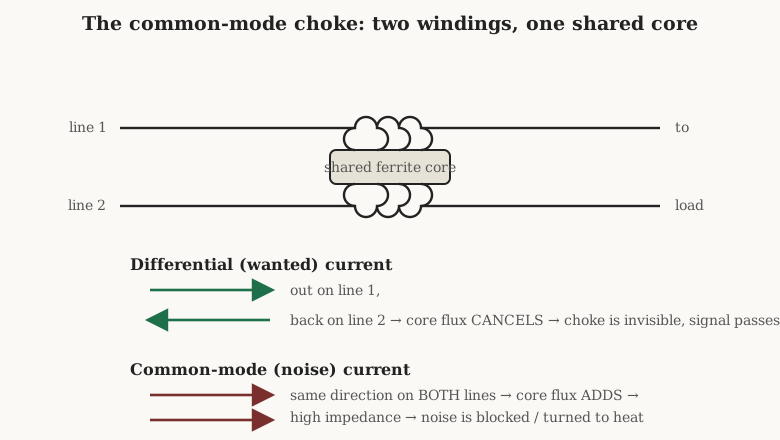
The common-mode choke is the elegant answer to common-mode noise. It winds both conductors of a pair onto a single shared core, in the same sense, so that the wanted differential current — equal and opposite in the two windings — produces two magnetic fields that cancel, leaving the choke nearly invisible to the signal or power it carries. Common-mode noise, flowing the same way in both windings, produces fields that add, so the choke presents a high impedance to it and chokes it off. The beauty is that a common-mode choke can carry a large differential current without saturating, because that current’s field cancels in the core; only the small common-mode component magnetises the core at all. Common-mode chokes sit on AC mains inputs, on USB and Ethernet and other data pairs, and on motor drive outputs, and they are wound parts — two coupled windings on a ferrite toroid or on a two-section bobbin — which is why they get a full treatment of their own in the specialty volume.
The blunter, cheaper cousin is the ferrite bead, and the key to understanding it is that it is not really an inductor in the usual sense — it is a deliberately lossy one. A bead is a small cylinder or block of lossy ferrite through which a wire passes (or around which a chip is wound). At low frequencies it does little; above a few megahertz the ferrite’s permeability goes resistive, and the bead behaves like a small frequency-dependent resistor, turning high-frequency noise currents into heat rather than reflecting them. This is why a bead is specified not by an inductance in henries but by its impedance at a stated frequency — a part might be quoted as 600 ohms at 100 MHz — because inductance would tell you nothing about the lossy region where the bead actually works. A bead in series with a power or signal pin damps high-frequency hash and tames ringing without storing energy to slosh back; the loss is the feature, not a defect.
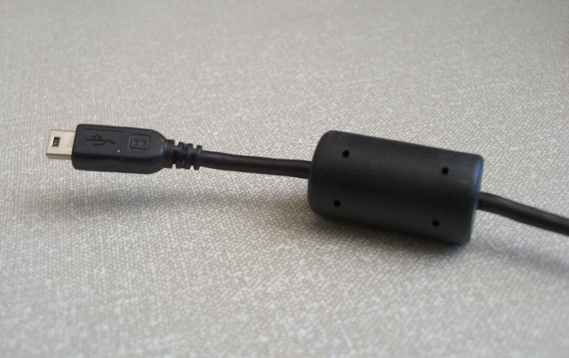
The clip-on ferrite core moulded around a monitor or USB cable is the same idea at cable scale: it slips over the whole bundle and acts on the common-mode current trying to travel along the cable’s outer surface as an antenna, adding impedance in the noise band without touching the differential signal inside. Beads and clamp cores are mass-produced ferrite parts; the common-mode choke is a wound one; but all three exploit the fact that a magnetic material’s impedance can be tuned in frequency to bite the noise and spare the signal.
10.6 Signal and audio
In the audio band the inductor’s job returns to filtering, but with a twist the power engineer rarely worries about: linearity. Audio is a signal you can hear, and any distortion the coil adds is a distortion in the sound, so the tolerance for core nonlinearity collapses.
The largest population of audio inductors lives in loudspeaker crossovers. A crossover splits the amplifier’s full-range signal so the woofer gets the lows and the tweeter the highs, and it does so with LC filters — an inductor in series with a woofer forms a low-pass that rolls off the treble, a capacitor in series with a tweeter forms the high-pass. The inductance values are large by electronics standards because the frequencies are low and the impedances are only a handful of ohms: woofer inductors commonly run from around 1 up to 5 or more millihenries, and because they carry the full current delivered to the driver — amps, at real power — they must not saturate.
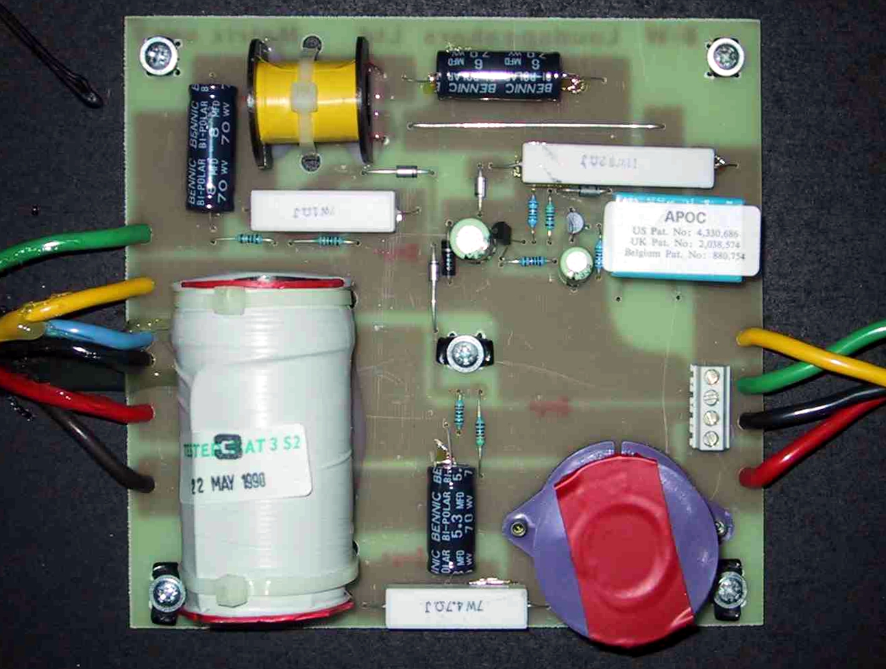
This is why the premium crossover inductor is air-cored: a big, heavy cylinder of many turns of thick copper wound on nothing but a plastic former. An air core cannot saturate and adds no magnetic distortion, so its inductance stays ruler-flat regardless of how hard the bass is driven — the linearity audio demands. The price is exactly the one the core-materials volume warned about: with no permeability multiplier, an air-core coil of useful inductance needs a great many turns, so it is large, heavy, expensive in copper, and burdened with DC resistance that eats amplifier power and damping. The cheaper alternative is an iron- or ferrite-cored crossover inductor, smaller and lower in resistance for the same inductance, accepted in budget or bass-only positions where a little saturation is tolerable, and avoided in the midrange where the ear is unforgiving. The choice is a direct, audible instance of the air-versus-core trade the whole series has been circling.
Elsewhere in audio the inductor is rarer but historically important. Plate chokes and choke-loaded stages appeared in valve amplifiers as high-impedance loads that passed the DC plate current while presenting a large reactance to the signal. The RIAA equalisation of a phono preamp is nowadays done with resistors and capacitors, but inductor-based equalisers and filters had their day, and audio chokes still smooth the supplies of amplifiers where the least hum is wanted — the same smoothing job as before, now judged by ear.
10.7 Sensing and transducers
An inductor’s inductance depends on its magnetic environment — how much iron is nearby, how the flux is coupled, whether a conductive target is in the field. That dependence, a nuisance in a precision RF coil, is the whole point of a large family of sensors, where the coil is deliberately arranged so that some physical quantity changes its inductance and the change is read out.
The inductive proximity sensor, ubiquitous on factory machinery, is a coil driven as part of an oscillator; when a metal target approaches, eddy currents induced in the target load the coil, drop its Q, and change the oscillation, which the sensor detects — a non-contact metal detector in a threaded barrel. The metal detector swept over a beach is the same principle at larger scale. The LVDT (linear variable differential transformer) measures position: a movable ferromagnetic core slides inside a set of windings, varying the coupling between a primary and two secondaries so the output voltage reports the core’s position with great precision and no wear — technically a transformer, and a pointer to the coming dive. Inductive position encoders extend the idea to rotation and to printed planar coils that need no wound part at all.
Current sensing leans on coils too. A current transformer clips around a conductor and reports the current flowing through it via the flux it produces, isolated and lossless — the clamp meter’s jaws are a split core with a winding. The Rogowski coil is a clever coreless variant: a helical winding wound around the conductor with no magnetic core, whose output is proportional to the rate of change of the enclosed current, integrated to recover the current itself; with no core it cannot saturate and can measure enormous, fast currents that would swamp an iron-cored transformer. Both are treated more fully when the transformers dive takes up coupled coils in earnest. Further afield, search coils and induction magnetometers measure magnetic fields themselves — a coil generates a voltage proportional to the rate of change of the flux through it, so a coil moved through a field, or sitting in a changing one, becomes a field sensor. In all of these the coil is a wound part whose geometry is the measurement, and the winding precision decides the accuracy.
10.8 Wireless power and coupling
Bring two coils close and the changing field of one threads the other, inducing a voltage in it — mutual inductance, the seed of the transformer and of every wireless-power link. When the two coils are not on a shared core but simply near each other in air, and both are tuned to resonance with capacitors, energy transfers across the gap with surprising efficiency. This is resonant inductive coupling, and it is how a phone charges on a pad without a connector.
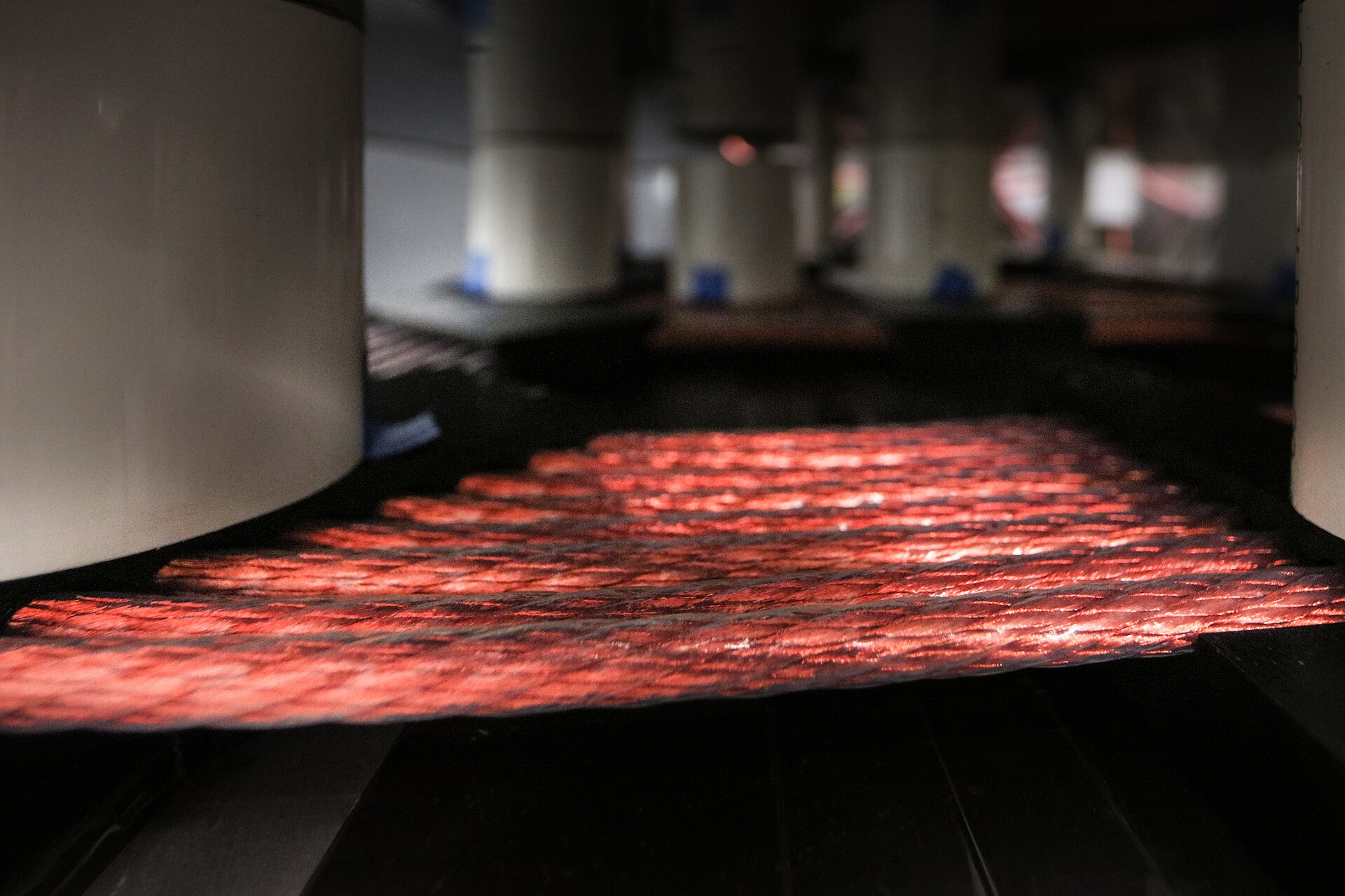
The Qi standard, in nearly every wireless charger, drives a flat spiral transmitter coil in the pad at a frequency in the low hundreds of kilohertz — roughly 100 to 205 kHz — and a matching receiver coil in the phone picks up the field; tuning both to resonance lets useful power, up to 15 watts for phones and far more for larger devices, cross a short air gap. The coils are flat spirals of Litz wire, wound to keep loss low because every ohm of coil resistance is efficiency lost as heat, and the coupling — and thus the efficiency — falls off sharply with distance and misalignment, which is why the phone must sit just so on the pad.
The same coupled-coil idea, run at higher frequency and looser coupling, is NFC and RFID. Here the coil is the antenna: a flat spiral etched on a card or wound on a ferrite, tuned to resonance at 13.56 MHz, that both couples power from the reader to a passive tag and carries the data back by modulating its own loading. A contactless payment card has no battery; it is a coil and a chip, powered entirely by the reader’s field through inductive coupling. Because the frequency is higher, the coupling can be looser than Qi’s, which is exactly why a card need only be waved near the reader rather than precisely placed. These are the closest cousins to the transformer among all the jobs in this volume — two coils sharing a field on purpose — and they lead naturally into the coming transformers dive, which is the study of coupling raised to a design discipline.
10.9 Motors, relays, solenoids, and ignition
The oldest job of all is the crudest: a coil is an electromagnet, and a great deal of the world’s machinery runs on coils used simply to turn current into force or motion. A relay is a coil that pulls an iron armature to close a contact; a solenoid is a coil that yanks a plunger to shift a valve, throw a lock, or bang a fuel injector open; a motor is an artful arrangement of coils whose fields push against each other or against magnets to spin a shaft. In each, the coil is a wound bobbin of many turns sized for the ampere-turns of force needed and the heat the winding can shed, and the design is a study in the magnetic-circuit and thermal reasoning of the earlier volumes rather than in reactance or Q.
One member of this family circles all the way back to the opening volume’s warning about inductive kick. The automobile ignition coil is, at heart, an energy-storage inductor with a second winding: current builds a strong magnetic field in the primary, and when a switch abruptly interrupts that current, the field collapses in an instant and the coil’s insistence on maintaining current flings the stored energy into a voltage spike — tens of thousands of volts, stepped up further by the turns ratio of the secondary — enough to arc across the spark plug. It is the same flyback energy that destroys a switch across an unprotected relay coil, here harnessed on purpose. Every internal-combustion engine ever built has depended on an inductor’s refusal to let its current stop quietly, which is a fitting note on which to close a survey of what these devices are for: even the most violent, useful trick in the catalogue is nothing more than the first volume’s ½LI² insisting on being spent.
10.10 The same component, many jobs
Line the domains up and a pattern emerges that explains why coil winding remains a live craft rather than a museum piece. Where the job needs high Q and stability — the RF tank, the oscillator, the loading coil — the part is a carefully hand- or precision-wound air-core or slug-tuned coil, because no moulded chip matches a good coil for Q. Where it needs to store energy against a DC bias — the switching-converter inductor — it is a mass-produced shielded chip on a gapped or powder core, chosen from a catalogue by Isat, Irms, and value. Where it must smooth or filter power — the DC choke, the PFC choke — it is a wound, laminated or ferrite bobbin part, closer to a small transformer. Where it must kill noise, it is a ferrite bead bought by its impedance curve or a wound common-mode choke on a shared core. Where it must not distort — the crossover inductor — it is a big air-cored cylinder whose size is the price of linearity. Where it must sense or couple, it is a wound sensor or a flat spiral antenna whose geometry is the whole function. And where it must simply pull, it is an electromagnet’s bobbin.
Three plain facts — energy stored in a field, opposition to changing current, reactance that climbs with frequency — fan out into that whole catalogue. Some entries have collapsed into anonymous surface-mount parts; a great many have not, because the value that matters (Q, linearity, a specific saturation ceiling, a precise coupling) still has to be wound in. That is the through-line of this series: understanding what an inductor is for is also understanding why someone, somewhere, is still turning a winder. The next volumes return to the bench — the specialty and variable parts that several of these jobs quietly depend on, the instruments that measure whether a coil met its spec, and the worked projects that put the winders to use.
Comments (0)