Coils and Coil Winding · Volume 14
Reference: Glossary, Tables, and Formulas
14.1 How to use this reference desk
The thirteen volumes before this one told a story; this one is a lookup. It gathers the definitions, material numbers, wire data, equations, and core figures scattered across the dive into one place a builder can reach for at the bench without re-reading a chapter. Nothing here is new — every entry traces back to a full treatment elsewhere in the series, and the cross-references point the way (“covered fully in the core-materials volume,” “worked in the design volume”). The aim is a faithful index, not a second opinion: the numbers below are the same numbers the earlier volumes used, drawn from manufacturer literature (Fair-Rite, Micrometals, Magnetics Inc., Amidon, Coilcraft), the ARRL Handbook, McLyman, and the NEMA and standard AWG data.
One standing caution governs the whole desk. Magnetic parts are specified to tolerances, and their behaviour drifts with frequency, temperature, and drive level. The tables give representative, illustrative figures — enough to size a coil and pick a core — but a design that only just clears a limit on paper must be confirmed against the specific datasheet and, ultimately, on the meter. The measurement volume is the other half of every number printed here.
Glossary
Alphabetized. Each entry is one to three sentences; the fuller treatment lives in the volume named in the text.
Table 1 — Glossary
| Term | Definition |
|---|---|
| Air gap | A deliberate break of low permeability (a slot in a ferrite, or the distributed micro-gaps in a powder core) inserted into a magnetic path. It lowers effective permeability but linearises the B–H curve, raises the saturation current, and stores most of the coil’s energy in the gap itself. |
| Air core | A winding on a non-magnetic former (plastic, ceramic) or on nothing at all; relative permeability 1, no saturation, no core loss, perfectly linear, but low inductance per turn. |
| A_L value | The inductance index of a specific core: the inductance per turn squared, so that L = A_L·N². Quoted variously in nH/N² (Micrometals), µH per 100 turns (Amidon “T” iron-powder cores), or mH per 1000 turns (Amidon “FT” ferrite cores). |
| Ampere-turns (N·I) | The magnetomotive force driving flux around a magnetic circuit; the true magnetic “drive” of a coil. Twenty turns at one amp and one turn at twenty amps produce the same magnetic effect. |
| Amorphous metal | A rapidly quenched magnetic alloy (Metglas and kin) whose atoms never crystallise; iron-based grades reach B_sat ≈ 1.5–1.6 T at low loss, used in high-efficiency line- and low-kHz transformers. |
| Arbor / mandrel / former / bobbin | The support a coil is wound on. A former or bobbin stays in the finished part; a mandrel or arbor is a temporary shaft removed after winding (as for a self-supporting air-core coil). Covered in the winding-machines volume. |
| AWG (American Wire Gauge) | The North-American numbering for round copper wire; higher number = thinner wire. Diameter changes ×2 every 6 gauges; area and DC resistance change ×2 every 3 gauges. Also called Brown & Sharpe gauge. |
| Back-EMF | The voltage a coil induces in itself when its own current changes, opposing that change (Faraday plus Lenz). The source of the inductive kick when current is interrupted. |
| Bank winding | A multilayer RF geometry ordered so that turns adjacent in space are also adjacent in the winding sequence, keeping inter-turn voltage — and thus self-capacitance — low. |
| Basket-weave winding | An RF coil wound through an odd number of pegs or slots so successive turns cross at a steep angle in mostly air; low self-capacitance, high Q. See the geometries volume. |
| B–H loop (hysteresis loop) | The closed curve traced by flux density B against field strength H over one cycle; its enclosed area is the hysteresis energy lost per cycle. Its knees mark saturation. |
| Bifilar winding | Two wires wound together as a pair for near-unity coupling and minimal leakage inductance; the basis of good common-mode chokes, baluns, and transmission-line transformers. |
| Bobbin core (drum core) | An open spool of core material — a rod with flanges — wound and left open; cheap and easy to wind, leaky, the body of many small SMD power inductors and axial RF chokes. |
| Choke | An inductor named for its job: to present a high impedance to AC (broadband or over a band) while passing DC or a lower frequency. An RF choke blocks radio frequencies; a filter choke smooths a rectified supply. |
| Coercivity (H_c) | The reverse field strength needed to drive a magnetised core’s flux density back to zero; low in soft core materials, high in permanent magnets. |
| Common-mode choke | Two windings on one core wound so the wanted differential current’s flux cancels (low impedance, signal passes) while common-mode noise current’s flux adds (high impedance, noise blocked). |
| Common mode vs differential mode | On a pair of wires, differential current flows out on one conductor and back on the other (the wanted signal); common-mode current flows the same direction on both, returning through ground (the interference). |
| Core loss | Energy dissipated in the magnetic material per cycle, the sum of hysteresis and eddy-current loss; depends on flux swing and frequency, not directly on load current. Modelled by Steinmetz: P_v ≈ k·f^α·B^β. |
| Curie temperature | The temperature above which a material ceases to be ferromagnetic and its permeability collapses toward 1. ~200–250 °C for power MnZn ferrite, ~570 °C nanocrystalline, ~745 °C silicon steel. |
| DCR (DC resistance) | The plain ohmic resistance of the winding copper; sets I²R heating, the DC voltage drop, and (at low frequency) the loss that limits Q. Rises ~0.39% per °C. |
| Eddy currents | Circulating currents a changing flux induces inside a conductive core; they dissipate energy and rise as the square of frequency and flux. Fought by laminating, by high-resistivity ferrite, and by insulated-grain powder cores. |
| ESR (equivalent series resistance) | The single series resistance that represents all of a coil’s losses (DCR plus AC copper losses plus reflected core loss) at a given frequency; it is the R in Q = X_L/R. |
| E-core / EI / ETD / PQ | Two-piece power core shapes that clamp around a pre-wound bobbin; the centre leg is easily ground to set a gap. The workaday shape of switch-mode transformers and chokes. |
| Faraday’s law | The induced EMF around a loop equals the rate of change of flux linkage: EMF = −N·(dΦ/dt). A changing field, not a steady one, makes a voltage. |
| Ferrite | A sintered ceramic oxide of iron with manganese-zinc or nickel-zinc; high resistivity throttles eddy currents, so it works far higher in frequency than laminated metal. See MnZn and NiZn. |
| Ferrite bead | A short lossy ferrite sleeve over a single conductor — a one-turn inductor built to be lossy, rated in ohms of impedance at a stated frequency (commonly 100 MHz) rather than in henries, to turn HF noise into heat. |
| Fill factor (copper space factor) | The fraction of the winding window that ends up as copper; typically 0.4–0.6 for a real coil after enamel, layer insulation, bobbin walls, and slack. Round wire alone packs ~78% (square) to ~90% (hex). |
| Flux (Φ) | The total magnetic field threading a coil, measured in webers (Wb); the field density B times the area it passes through. Its rate of change is what induces voltage. |
| Flux density (B) | Magnetic field per unit area, measured in tesla (T) in SI, gauss in CGS (1 T = 10,000 gauss); the material’s response to the applied field strength H. |
| Field strength (H) | The applied magnetising effort, in ampere-turns per metre; for a toroid, H = N·I/l. Depends only on the winding and current, not on the core material. |
| Henry (H) | The SI unit of inductance: one volt-second per amp (1 V·s/A), equivalently one weber of flux linkage per amp. A large unit; board inductors run in mH, µH, and nH. Named for Joseph Henry. |
| High-Flux core | A 50% nickel / 50% iron powder core, B_sat ≈ 1.5 T, the highest DC-bias capability of the common powder family; used in heavy-bias and PFC chokes. |
| Honeycomb (duolateral) winding | See universal winding. |
| Hysteresis loss | The energy spent each cycle re-aligning magnetic domains, equal to the B–H loop area times frequency; rises with frequency and steeply with peak flux density. |
| Impedance (Z) | The complex opposition of a real coil to AC, magnitude and phase together: below self-resonance mainly the reactance X_L, with the loss resistance in quadrature. |
| Inductance (L) | The property relating the voltage across a coil to the rate of change of its current (v = L·di/dt); the measure of a coil’s opposition to a change in current. |
| Isat (saturation current) | The DC current at which inductance has fallen by a stated fraction (10%, 20%, or 30% — always quote which) from its zero-current value, as the core saturates. |
| Irms (thermal current rating) | The RMS current that raises the part’s temperature by a specified amount through I²R heating, independent of saturation. A coil must clear both Isat and Irms; the lower governs. |
| Laminations | Thin insulated sheets of silicon steel stacked to build a core, breaking eddy-current loops into small ones; the construction of every mains and audio transformer core. |
| Lenz’s law | The induced current (and voltage) always opposes the change that produced it; the source of the minus sign in Faraday’s law and of a coil’s “electrical inertia.” |
| Litz wire | Many fine, individually insulated strands twisted so each takes every radial position along the length, defeating skin and proximity effect; worth its cost from tens of kHz to a few MHz. |
| Loading coil | A series inductor added to an electrically short antenna or a telephone line to supply missing inductance and restore resonance or flatten response (Pupin/Heaviside). |
| Magnet wire (enamelled wire) | Solid copper (occasionally aluminium) coated with a thin baked polymer film a few to tens of microns thick — thin enough that turns pack essentially copper-to-copper. |
| MMF (magnetomotive force) | The magnetic analogue of voltage, N·I in ampere-turns, that drives flux through a magnetic circuit against its reluctance. |
| MnZn ferrite | Manganese-zinc ferrite: higher permeability (µr ~1,000–15,000), B_sat ~0.4–0.5 T, useful from a few kHz to ~1–3 MHz; the material of switch-mode transformers and chokes. |
| MPP (molypermalloy powder) | A ~79% Ni / 17% Fe / 4% Mo powder core, µr ~14–550, B_sat ~0.75 T; the lowest loss and best temperature stability of the powder family, at a nickel-driven price premium. |
| Mutual inductance (M) | The coupling between two windings, M = k√(L₁·L₂), where k (0–1) is the coupling coefficient; the seed of the transformer, treated in the companion transformers dive. |
| Nanocrystalline alloy | A fine-grained tape alloy (FINEMET, VITROPERM), µr up to >100,000, B_sat ~1.2–1.3 T, very low loss; superb common-mode chokes and HF power transformers, at high cost. |
| NiZn ferrite | Nickel-zinc ferrite: lower permeability (µr ~15–800) but far higher resistivity, B_sat ~0.25–0.35 T, useful from ~1 MHz to hundreds of MHz; the material of RF chokes, beads, and baluns. |
| Permeability (µ, µr) | How readily a material carries magnetic flux; µ = B/H. The relative permeability µr = µ/µ0 is the dimensionless multiplier a core applies to a coil’s inductance (air = 1). |
| Pi winding (sectioned winding) | A choke wound as several narrow series-connected sections separated by flanges; the section capacitances series-add and the resonances stagger, keeping the RF choke inductive across a wide band. |
| Potting / impregnation | Filling a finished winding with varnish, resin, or wax to lock the turns, exclude moisture, conduct heat, and quiet mechanical buzz; covered in the winding-technique volume. |
| Pot core / RM core | A core shaped as cups that close around the winding, wrapping it in material; the most shielded shapes, prized for stable low-EMI filter inductors, often with an adjustable centre slug. |
| Powdered iron (carbonyl) | Insulated iron powder pressed into cores (the colour-coded Amidon/Micrometals toroids), µr ~3–100, B_sat ~1.0–1.5 T; stable, gradual saturation, moderate-to-high loss; RF tuned circuits and DC-bias chokes. |
| Proximity effect | The crowding of a conductor’s current by the alternating field of neighbouring turns; often dominates skin effect in multilayer windings and can multiply AC resistance several-fold. |
| Q (quality factor) | Reactance over loss resistance, Q = X_L/R = 2πfL/R; equivalently 2π times energy stored per energy lost per cycle. High Q for tuned circuits; deliberately low for damping and EMI parts. |
| Reactance (X_L) | The frequency-dependent opposition of an ideal inductor to AC, X_L = 2πfL, in ohms; zero at DC, rising with frequency — the reason a coil “chokes” AC. |
| Reluctance (ℛ) | The magnetic circuit’s resistance to flux, ℛ = l/(µ·A); reluctances in series add, and an air gap is simply a large reluctance in series with the low-reluctance core. |
| Remanence (B_r, retentivity) | The flux density that remains in a core when the drive current returns to zero; the leftover magnetism, read off where the B–H loop crosses the vertical axis. |
| RFC (radio-frequency choke) | An inductor that blocks RF while passing DC or audio, feeding supply to a stage without letting signal escape up the supply line; usually pi-wound or ferrite/iron-cored to stay inductive across a band. |
| Ring test (ringdown test) | A shorted-turn detector: pulse the coil with a capacitor across it and count the ringing cycles; a healthy high-Q coil rings many cycles, one shorted turn collapses Q so it dies in one or two. |
| Saturable reactor | A reactor whose AC inductance is controlled by a DC bias winding that pushes the core toward saturation; the basis of the magnetic amplifier and of mag-amp post-regulators. |
| Saturation (B_sat, Isat) | The flux-density ceiling where a core’s domains are nearly all aligned; beyond it incremental permeability collapses toward air’s and the inductance falls off a cliff. B_sat falls as the core warms. |
| Self-bonding (bondable) wire | Magnet wire with an extra thermoplastic overcoat that softens with heat or solvent and fuses the turns into a rigid mass; how a freestanding air-core coil is made. |
| Self-capacitance (winding capacitance, Cw) | The distributed capacitance between turns and layers, appearing in parallel with L; set by winding geometry, it fixes the self-resonant frequency. |
| Self-resonant frequency (SRF) | Where the winding capacitance resonates with the inductance, f_SRF = 1/(2π√(L·Cw)); above it the “inductor” is capacitive. Keep the operating frequency well below (often < f_SRF/10). |
| Sendust (Kool Mµ) | An iron-silicon-aluminium powder core (~85/9/6), µr ~26–125, B_sat ~1.0 T; low cost (no nickel), good loss and thermal behaviour — a default SMPS/PFC choke material. |
| Skin effect | The crowding of AC toward a conductor’s surface; effective current confines to a shell about a skin depth δ thick, so above a couple of skin depths a fatter wire barely lowers AC resistance. |
| Skin depth (δ) | The depth at which AC current density falls to 1/e of its surface value, δ = √(ρ/(πfµ)); ≈ 66 µm in copper at 1 MHz, scaling as 1/√f (≈ 2.1 mm at 1 kHz). |
| Slug / permeability tuning | Adjusting inductance by screwing a magnetic or metallic core into the winding: a ferrite/iron slug raises L; a brass/aluminium slug (a shorted turn) lowers it. Ferrite up, brass down. |
| Solenoid | A single uniform helical layer of wire on a cylinder; the archetypal coil, low self-capacitance and high RF Q, and the basis of Wheeler’s design formula. |
| Tap | A connection brought out partway along a winding, dividing the inductance for impedance matching, band switching, or autotransformer action. |
| Tensioner | The winding-machine element that holds the wire under controlled, constant tension so turns lie tight and even without stretching or nicking the enamel. See the machines volume. |
| Toroid | A ring core wound around its cross-section; a closed, nearly gap-free magnetic path that is self-shielding (little external field) but must be wound turn-by-turn through the hole. |
| Traverse / pitch | The axial motion of a winding machine’s wire guide that lays turns along the former; the pitch is the advance per turn (close-wound = one wire diameter, spaced = more). |
| Turns counter | The geared or electronic register on a winder that counts revolutions so a coil receives exactly the number of turns specified. |
| Universal (honeycomb / duolateral) winding | A machine winding that lays wire at a steep, reversing angle so successive turns cross rather than run parallel, slashing self-capacitance and lifting RF Q. |
| Variometer | A continuously variable inductor: an inner coil rotates inside a series-connected outer one, varying their mutual coupling so L = L₁ + L₂ ± 2M; contactless, gap-free, and used at high power. |
| Wheeler’s formula | Harold Wheeler’s 1928 empirical single-layer solenoid equation, L(µH) = r²N²/(9r+10l) (r, l in inches), accurate to ~1% for ordinary proportions (l ≳ 0.4r, best ≳ 0.8r). |
14.2 Master core-material comparison
Frequency first, then saturation, then loss — that is the order in which a core is chosen, and this table is its menu. Permeability and B_sat vary by grade within each family; the ranges are illustrative, drawn from manufacturer literature, and any real design confirms against the specific datasheet. This is the condensed form of the table in the core-materials volume.
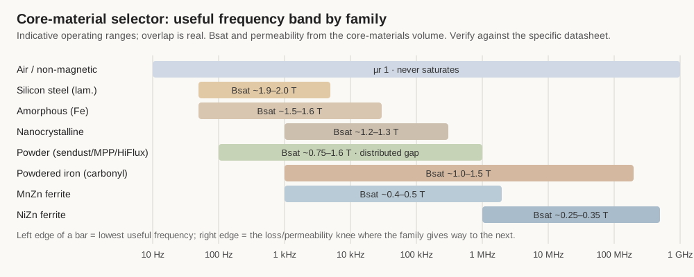
Table 2 — Master core-material comparison
| Family | Material system | µr (initial) | B_sat (approx.) | Useful frequency | Relative core loss | Temp. / stability | Typical uses |
|---|---|---|---|---|---|---|---|
| Air / non-magnetic | none (µr = 1) | 1 | none — never saturates | DC to > 1 GHz | none | perfect linearity; drifts only with former expansion | High-power RF tanks, high-linearity filters, > 100 MHz |
| Silicon steel (laminated) | Fe + ~3% Si, thin laminations | ~2,000–40,000 | ~1.9–2.0 T | 50 Hz – audio | high above audio | Curie ~745 °C; loss-limited, not heat-limited | Mains & audio transformers, line/filter chokes |
| Amorphous (Fe-based) | rapidly quenched Fe alloy tape | ~10,000+ | ~1.5–1.6 T | line – tens of kHz | low | high Curie; very stable | High-efficiency power transformers |
| Nanocrystalline | FINEMET / VITROPERM tape | up to > 100,000 | ~1.2–1.3 T | kHz – hundreds of kHz | very low | Curie ~570 °C; excellent | Common-mode chokes, HF power transformers |
| MnZn ferrite | Mn-Zn oxide ceramic | ~1,000–15,000 | ~0.4–0.5 T (≈0.35 T hot) | kHz – ~1–3 MHz | low (in band) | Curie ~200–250 °C; B_sat falls with heat | SMPS transformers/chokes, LF EMI suppression |
| NiZn ferrite | Ni-Zn oxide ceramic | ~15–800 | ~0.25–0.35 T | ~1 MHz – hundreds of MHz | low (in band) | higher Curie than MnZn | RF chokes, beads, baluns, wideband RF |
| Powdered iron (carbonyl) | insulated iron powder | ~3–100 | ~1.0–1.5 T | LF – VHF (RF mixes) | moderate–high | stable; some mixes age if run hot | RF tuned circuits & traps, DC-bias chokes |
| Sendust (Kool Mµ) | Fe-Si-Al powder (~85/9/6) | ~26–125 | ~1.0 T (~10,500 G) | LF – ~1 MHz | moderate | good; distributed gap | Cost-effective SMPS / PFC chokes |
| MPP | Ni-Fe-Mo powder (~79/17/4) | ~14–550 | ~0.75 T (~7,500 G) | LF – ~1 MHz | lowest of powders | best of powders | Low-loss, stable filter / resonant chokes |
| High-Flux / XFlux | 50% Ni-Fe / 6.5% Si-Fe powder | ~14–160 | ~1.5–1.6 T (~15,000 G) | LF – ~1 MHz | moderate | good DC-bias | Heavy DC-bias chokes, PFC |
14.3 Magnet wire: the AWG table
Bench-usable sizes, AWG 10 through 44. Diameter and area are the bare copper conductor before enamel; the overall diameter with film is larger and depends on build grade. DC resistance is annealed copper at 20 °C. The final column is not an ampacity rating — it is the current at a single deliberately conservative loading of 700 circular mils per ampere, given only for a feel of scale. This is the same table as in the magnet-wire volume; the mental checks hold across it (×2 area every 3 gauges, ×2 diameter every 6 gauges).
Table 3 — Magnet wire: the AWG table
| AWG | Bare dia (mm) | Area (mm²) | Area (cmil) | Ω / 1000 ft | Ω / km | Current @ 700 CM/A |
|---|---|---|---|---|---|---|
| 10 | 2.588 | 5.26 | 10,380 | 0.999 | 3.28 | 15 A |
| 12 | 2.052 | 3.31 | 6,530 | 1.588 | 5.21 | 9.3 A |
| 14 | 1.628 | 2.08 | 4,110 | 2.525 | 8.28 | 5.9 A |
| 16 | 1.290 | 1.31 | 2,580 | 4.016 | 13.17 | 3.7 A |
| 18 | 1.024 | 0.823 | 1,620 | 6.385 | 20.9 | 2.3 A |
| 20 | 0.813 | 0.518 | 1,020 | 10.15 | 33.3 | 1.5 A |
| 22 | 0.645 | 0.326 | 640 | 16.14 | 52.9 | 0.92 A |
| 24 | 0.511 | 0.205 | 405 | 25.67 | 84.2 | 0.58 A |
| 26 | 0.404 | 0.129 | 255 | 40.81 | 133.9 | 0.36 A |
| 28 | 0.320 | 0.081 | 160 | 64.90 | 212.9 | 0.23 A |
| 30 | 0.254 | 0.0507 | 100 | 103.2 | 338.5 | 0.14 A |
| 32 | 0.203 | 0.0324 | 63 | 164.1 | 538.3 | 91 mA |
| 34 | 0.160 | 0.0201 | 40 | 260.9 | 855.8 | 56 mA |
| 36 | 0.127 | 0.0127 | 25 | 414.8 | 1360 | 35 mA |
| 38 | 0.102 | 0.0081 | 16 | 659.6 | 2163 | 23 mA |
| 40 | 0.0787 | 0.0050 | 9.9 | 1049 | 3440 | 14 mA |
| 42 | 0.0635 | 0.0032 | 6.3 | 1652 | 5421 | 8.9 mA |
| 44 | 0.0508 | 0.0020 | 4.0 | 2589 | 8495 | 5.7 mA |
Source: Remington Industries solid-copper / magnet-wire AWG data (bare diameter, area, DC resistance at 20 °C). Nominal values; the full AWG series runs from 4/0 down past AWG 50. Outside North America, wire is often sized directly by bare diameter in millimetres, and vintage British recipes use SWG, which does not equal the same-numbered AWG.
14.3.1 Insulation thermal classes and films
The enamel film sets the coil’s maximum temperature, solderability, abrasion resistance, and voltage withstand. Classes are standardised under NEMA MW 1000 (with matching IEC 60317 designations); the number is the temperature in °C at which the film is rated for long service life.
Table 4 — Insulation thermal classes and films
| Thermal class (°C) | Common film chemistry | Solderable? | Notes |
|---|---|---|---|
| 105 | Plain enamel (oleoresinous); Formvar (polyvinyl acetal) | Plain: yes · Formvar: no | Formvar is tough and abrasion-resistant, a hand-winding favourite; must be stripped to terminate. Plain enamel survives in pickup coils. |
| 155 | Polyurethane; polyurethane-nylon | Yes | The fine-wire / RF workhorse — the film floats off in a hot solder pot (~380–400 °C), no separate stripping. Nylon overcoat adds abrasion resistance. |
| 180 | Polyurethane (high-temp); polyester, polyester-imide | PU: yes · polyester: generally no | Polyester(-imide) is tougher and more heat/moisture resistant, for motors and transformers. |
| 200 | Polyester(imide) base + polyamide-imide (PAI) topcoat | No | The go-to for demanding, hot motors and transformers; strip to terminate. |
| 220–240 | Polyimide (“ML” / Kapton-type) | No | Extreme-temperature, aerospace and high-reliability; chemically near-inert, expensive, unforgiving to work. |
Build grade (film thickness) is separate from chemistry: NEMA Grade 1–4, trade single / heavy / triple / quad. Heavier build buys turn-to-turn voltage withstand and abrasion margin at the cost of fill factor. Details in the magnet-wire volume.
14.4 Formula cheat-sheet
The load-bearing equations, variables and units defined. SI throughout unless noted; µ0 = 4π×10⁻⁷ H/m ≈ 1.257×10⁻⁶ H/m.
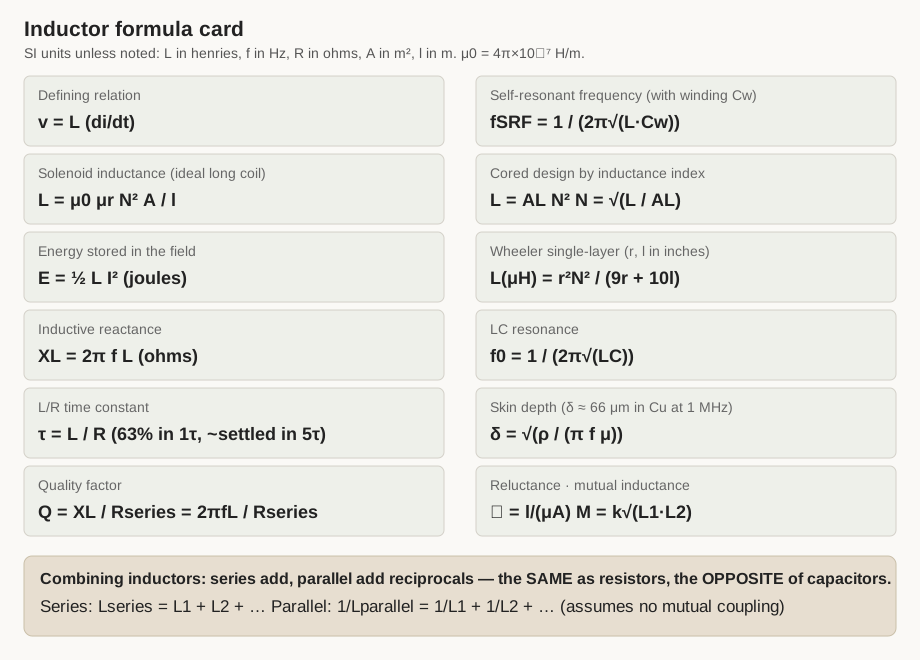
Table 5 — Formula cheat-sheet
| Quantity | Formula | Variables & units |
|---|---|---|
| Defining relation | v = L·(di/dt) | v volts; L henries; di/dt amps per second. Voltage appears only while current changes. |
| Solenoid inductance (ideal long coil) | L = µ0·µr·N²·A/l | A m² (core cross-section); l m (winding length); N turns. Over-estimates real finite coils — use Wheeler for practical air coils. |
| Stored energy | E = ½·L·I² | E joules; I amps. Energy lives in the magnetic field, not the copper. |
| Inductive reactance | X_L = 2π·f·L | X_L ohms; f hertz. Zero at DC, rises with frequency. |
| L/R time constant | τ = L/R | τ seconds; R ohms. ~63% of the change in 1τ, ~settled in 5τ. Dual of the capacitor’s RC. |
| Quality factor | Q = X_L/R_series = 2πfL/R_series | R_series = the effective series loss (DCR + AC copper + reflected core loss). Report the frequency with any Q. |
| Self-resonant frequency | f_SRF = 1/(2π√(L·Cw)) | Cw farads (winding self-capacitance). Above f_SRF the part is capacitive; keep operation below ~f_SRF/10. |
| Cored design by index | L = A_L·N² → N = √(L/A_L) | Write A_L’s units out (nH/N², µH/100t, or mH/1000t) and cancel them — a factor-of-100 or -10,000 trap otherwise. |
| Wheeler single-layer | L(µH) = r²·N²/(9r + 10l) | r, l in inches (r to wire centre); ~1% for l ≳ 0.8r. Empirical; confirm on the meter. |
| LC resonance | f₀ = 1/(2π√(L·C)) | f₀ hertz; C farads. The tuned-circuit frequency; also the basis of the LC-resonance measurement. |
| Skin depth | δ = √(ρ/(π·f·µ)) | ρ resistivity, µ permeability. Copper: δ ≈ 66 µm at 1 MHz, scaling as 1/√f. |
| Reluctance | ℛ = l/(µ·A) | Magnetic “resistance”; series-adds. An air gap is a large ℛ in series with the core’s small one. |
| Mutual inductance | M = k·√(L₁·L₂) | k coupling coefficient, 0–1. The transformer’s foundation (companion dive). |
Combining inductors (no mutual coupling): series adds — L_series = L₁ + L₂ + … — and parallel adds reciprocally — 1/L_parallel = 1/L₁ + 1/L₂ + …. This is the same rule as resistors and the opposite of capacitors, a swap worth committing to memory to avoid the classic sign-of-the-mistake error. When windings are coupled, the series combination becomes L₁ + L₂ ± 2M (the variometer’s mechanism).
14.5 Standard cores and A_L quick-reference
A short, illustrative set of the toroids a bench most often reaches for, with nominal A_L values worked from Amidon/Micrometals published data. Verify against the current datasheet before winding: A_L carries a real tolerance (typically ±5% for iron powder, wider for ferrite), and a given physical core can be catalogued differently by different vendors — Fair-Rite’s own current data for the FT50-43 equivalent, for instance, gives about 440 nH/N² against Amidon’s classic 523, both “correct.” Use these to get the turns close, then measure. The turns-for-target relation is N = √(L/A_L), with the unit convention below.
Iron-powder toroids (A_L in µH per 100 turns; L = A_L·(N/100)²). Mixes here are the two most common RF/carbonyl grades from the core-materials volume: mix 2 (red, µ ≈ 10) and mix 6 (yellow, µ ≈ 8.5).
Table 6 — Standard cores and AL quick-reference
| Core | OD (in) | Mix 2 (red) A_L | Mix 6 (yellow) A_L |
|---|---|---|---|
| T37 | 0.375 | 40 | 30 |
| T50 | 0.500 | 49 | 40 |
| T68 | 0.690 | 57 | 47 |
Worked check (matches the design volume): a T50-6 at A_L = 40 µH/100t is 4 nH/N²; 25 turns give L = 40·(25/100)² = 2.5 µH, or 4 nH·25² = 2,500 nH = 2.5 µH.
Ferrite toroids (A_L in mH per 1000 turns; L = A_L·(N/1000)²). Materials from the core-materials volume: 43 (NiZn, µ ≈ 800), 61 (NiZn, µ ≈ 125), 77 (MnZn, µ ≈ 2000).
Table 7 — Standard cores and AL quick-reference
| Core | OD (in) | Mat. 43 A_L | Mat. 61 A_L | Mat. 77 A_L |
|---|---|---|---|---|
| FT50 | 0.500 | 523 | 68 | 1,100 |
| FT82 | 0.825 | 557 | 73 | 1,170 |
Note the unit gulf: 523 mH/1000t equals 523 nH/N², so a single turn on an FT50-43 is ~0.52 µH and ten turns ~52 µH — high-permeability ferrite reaches large inductance in very few turns, which is exactly why it saturates at low current and suits chokes and wideband transformers rather than energy storage.
14.5.1 Iron-powder colour code and frequency guidance
Iron-powder mixes are painted a standard colour so the material — and its permeability and frequency home — can be read from the parts bin. The common mixes:
Table 8 — Iron-powder mixes are painted a standard colour so the material — and its permeability and frequency home — can be read from the parts bin. The common mixes
| Mix | Colour | µ (approx.) | Frequency home |
|---|---|---|---|
| 0 | tan | 1 | > 100 MHz (air-equivalent) |
| 1 | blue | 20 | 0.5 – 5 MHz |
| 2 | red | 10 | 2 – 30 MHz |
| 3 | grey | 35 | 0.05 – 0.5 MHz |
| 6 | yellow | 8.5 | 10 – 50 MHz |
| 10 | black | 6 | 30 – 100 MHz |
| 12 | green/white | 4 | 50 – 200 MHz |
| 15 | red/white | 25 | 0.1 – 2 MHz |
| 26 | yellow/white | 75 | DC – 1 MHz (power / EMI) |
Amidon/Micrometals iron-powder colour convention. Higher-µ mixes serve lower frequencies; the lowest-µ mixes carry on into VHF. A mix chosen above its frequency home loses Q to rising core loss.
14.6 Winding quick-reference
A compact bench cheat-sheet for the physical act of winding; the full craft is in the winding-technique and machines volumes.
Toroid turns-length estimate. Turns crowd toward the inner hole, so the inner circumference (π × inner diameter) is the binding dimension for a single layer. Turns that fit in one layer ≈ (π × ID) / (wire diameter over enamel), derated for slack. Wire needed ≈ N × (mean turn length), where the mean turn length is roughly the core’s cross-section perimeter plus a little for the inner-corner crowding. Always wind a couple of turns high and trim to the measured value.
Close-wound turns per inch (bare copper, close-wound single layer). Approximate — build grade adds to the pitch. From the AWG table, turns/inch ≈ 25.4 / (bare diameter in mm), then reduce a little for the enamel wall.
Table 9 — Winding quick-reference
| AWG | Bare dia (mm) | ≈ turns per inch (close-wound) |
|---|---|---|
| 20 | 0.813 | ~29 |
| 24 | 0.511 | ~46 |
| 26 | 0.404 | ~58 |
| 30 | 0.254 | ~90 |
| 34 | 0.160 | ~140 |
Tension and insulation reminders. Wind under steady, moderate tension — enough that turns lie tight and even, not so much that the wire stretches or the enamel is nicked or scraped through. Interleave layer insulation where the accumulated inter-layer voltage warrants it, both for withstand and to lower self-capacitance. Choose a solderable polyurethane-family film for coils with many fine leads to terminate; accept a strip-to-terminate film (Formvar, polyester, PAI, polyimide) only where temperature or toughness demands, and verify bright copper — not brown film — is wetted at every joint.
The two rules that catch everyone. First, measure at the operating frequency and under bias: a cored coil reads a different inductance at 1 kHz than at its working frequency, and a power inductor reads far less under its DC load current than idle — so a coil is characterised where it will actually live, not at the meter’s default. Second, ring-test for shorted turns: a single shorted turn barely moves the inductance but wrecks performance; pulse the coil with a capacitor across it and count the ringing cycles — a fast decay condemns the winding regardless of what the inductance meter says.
14.7 Further reading and standards index
Accurately named references behind the numbers in this dive. Editions vary; cite the one in hand.
Handbooks and textbooks
- The ARRL Handbook for Radio Communications — American Radio Relay League (annual). The standard practical reference for RF coils, Wheeler’s formula, iron-powder and ferrite core data, and tuned-circuit design.
- Colonel Wm. T. McLyman, Transformer and Inductor Design Handbook (CRC Press). The definitive text on area-product core selection, gapping, energy storage, and thermal design.
- Frederick E. Terman, Radio Engineers’ Handbook (McGraw-Hill). Classic-era coverage of coil design, Q, and self-capacitance (Medhurst’s and Wheeler’s data).
- ITT Reference Data for Radio Engineers / Reference Data for Engineers (Howard W. Sams). Broad tables including AWG, skin depth, and coil formulas.
- E. C. Snelling, Soft Ferrites: Properties and Applications (Butterworths). The reference on ferrite material behaviour, loss, and permeability versus frequency.
Manufacturer literature and application notes
- Micrometals — iron-powder and sendust core catalogues and the “Iron Powder Cores for Switchmode Power Supply Inductors” application material; A_L tables and mix data.
- Amidon Associates — the widely used Amidon Tech Data Flyer, with iron-powder (“T”) and ferrite (“FT”) toroid A_L values, colour codes, and dimensions.
- Fair-Rite Products — ferrite material datasheets (materials 43, 61, 77, and kin), bead impedance curves, and DC-bias derating.
- Magnetics Inc. — Kool Mµ (sendust), MPP, High-Flux, and XFlux powder-core catalogues, DC-bias and core-loss curves.
- TDK / EPCOS, Ferroxcube, Würth Elektronik, Bourns, Coilcraft — power-ferrite material data (N87 and equivalents), core geometries, and finished-inductor datasheets defining L, DCR, Q, SRF, Isat, and Irms with their test conditions.
Standards
- NEMA MW 1000 — Magnet Wire — the North-American standard for enamelled winding wire: thermal classes, build grades, and film chemistries.
- IEC 60317 — the international counterpart series specifying magnet-wire types and dimensions.
- ASTM B258 — standard nominal diameters and cross-sectional areas of solid round wire (the AWG series).
- IEC 62044 / IEC 63093 — soft-ferrite core measurement methods and standardised core shapes.
Reputable online resources
- toroids.info — per-core datasheet summaries (A_L, dimensions) for common Amidon/Fair-Rite toroids.
- coil32.net — coil and toroid inductance calculators (single-layer, multilayer, iron-powder and ferrite A_L).
- The manufacturers’ own online core and inductor selector tools (Coilcraft, Würth, Magnetics, TDK) — the fastest path from a target L-and-current to a candidate part, and the authoritative source for the datasheet numbers these tables only illustrate.
The rest of this dive is the reasoning behind these entries: what an inductor is and why it resists change, the real coil’s losses and limits, the history, the core materials and magnet wire tabulated above, the winding geometries and the machines and craft that lay them down, the design arithmetic that turns a target value into turns, where inductors are used, the specialty and variable types, and how to measure what comes off the winder. This desk is where those threads are meant to be found again in a hurry.
Comments (0)