Coils and Coil Winding · Volume 13
Build Your Own: Worked Coil-Winding Projects
13.1 How to use this volume
Everything up to this point has been preparation. The physics of the magnetic field, the non-ideal parasitics, the core materials and the magnet wire, the geometries, the machines, the winding technique, the design formulas, and the bench instruments — each was a chapter in a manual whose only real purpose is to let a person sit down at a winder and produce a coil that does a specific job to a specific number. This is that sitting-down. What follows is a handful of complete, buildable projects, each one carried the whole way from a value on a schematic to a wound part measured on the bench and confirmed to be what the design asked for.
The projects are deliberately ordinary. There is nothing exotic here — an air-core RF coil, a toroidal choke, a switching-supply inductor, a common-mode choke, a tapped coil — because the ordinary parts are exactly the ones a builder actually needs and the ones whose numbers are easiest to check against published data. Every core named below is a real, orderable part with a published inductance index; every turns count was computed from that index by the methods of the design volume, not reverse-engineered from a desired answer; and every project ends with a measurement and a target it has to hit. Where a value is an approximation — and several are, because empirical coil formulas and tolerance-banded cores guarantee it — the text says so.
Each project runs through the same five beats, and a reader can follow the pattern from one to the next:
- Goal — the value, the frequency or current, and the job the coil does.
- Parts — the core or former, the wire gauge, and a small turns table. The core and wire choices lean on the reasoning of the core-materials and magnet-wire volumes; the parts table is the short version.
- Turns calculation — Wheeler’s formula for air-core solenoids, the inductance index (the manufacturer’s AL, quoted as microhenries per hundred turns or nanohenries per turn-squared) for cored parts, worked out in full so the arithmetic is visible.
- Winding steps — how the coil is physically put on the former or core, on the machines and by the technique of the winding volumes: tension, pitch, anchoring, terminating.
- Measure and verify — the value read back on the meter, the target it is compared against, and how to nudge a near-miss into tolerance.
A short troubleshooting section at the end gathers the failures common to all of them. And because the whole exercise is pointless without the last step, one figure is worth studying before any wire is cut.
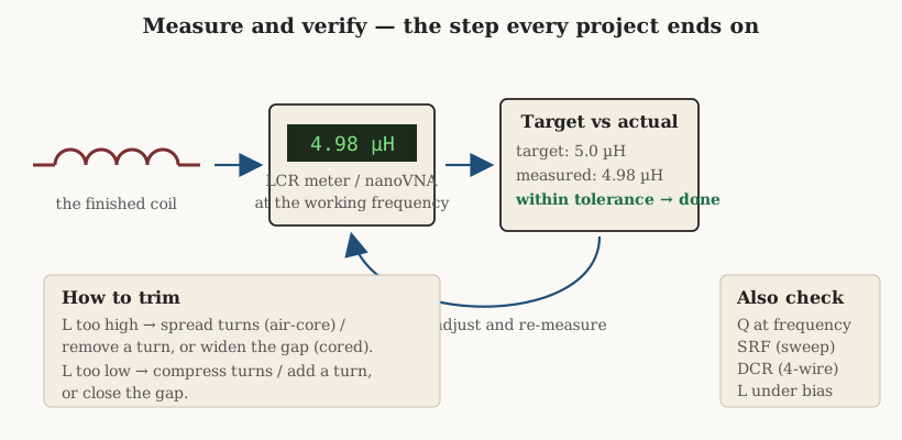
The instruments and methods behind that loop — reading inductance, Q, and DC resistance at a stated frequency, finding the self-resonant frequency, testing under DC bias, and the ring test for a shorted turn — belong to the measurement volume; here they are simply used. One habit is worth stating once and then assuming throughout: a coil is not finished when the last turn is wound, it is finished when the meter agrees with the design. Winders who skip the measurement are not building coils, they are making decorations that happen to have inductance.
13.2 Project 1 — An air-core RF coil, about 5 µH
Goal. A single-layer air-core coil of roughly 5 µH, the sort of value that pairs with a variable capacitor to tune the low end of the high-frequency spectrum, or forms the inductor in a trap or an LC tank in a receiver front end. Air-core is chosen for the reason the applications volume gave: at radio frequency the coil’s Q sets the selectivity of whatever it tunes, and a well-built air-core solenoid reaches a Q of a couple of hundred where a cored part struggles past twenty. There is no core to saturate, no core loss, and no temperature drift beyond the copper’s own — the trade is size, because without a permeability multiplier the coil needs real turns on a real diameter.
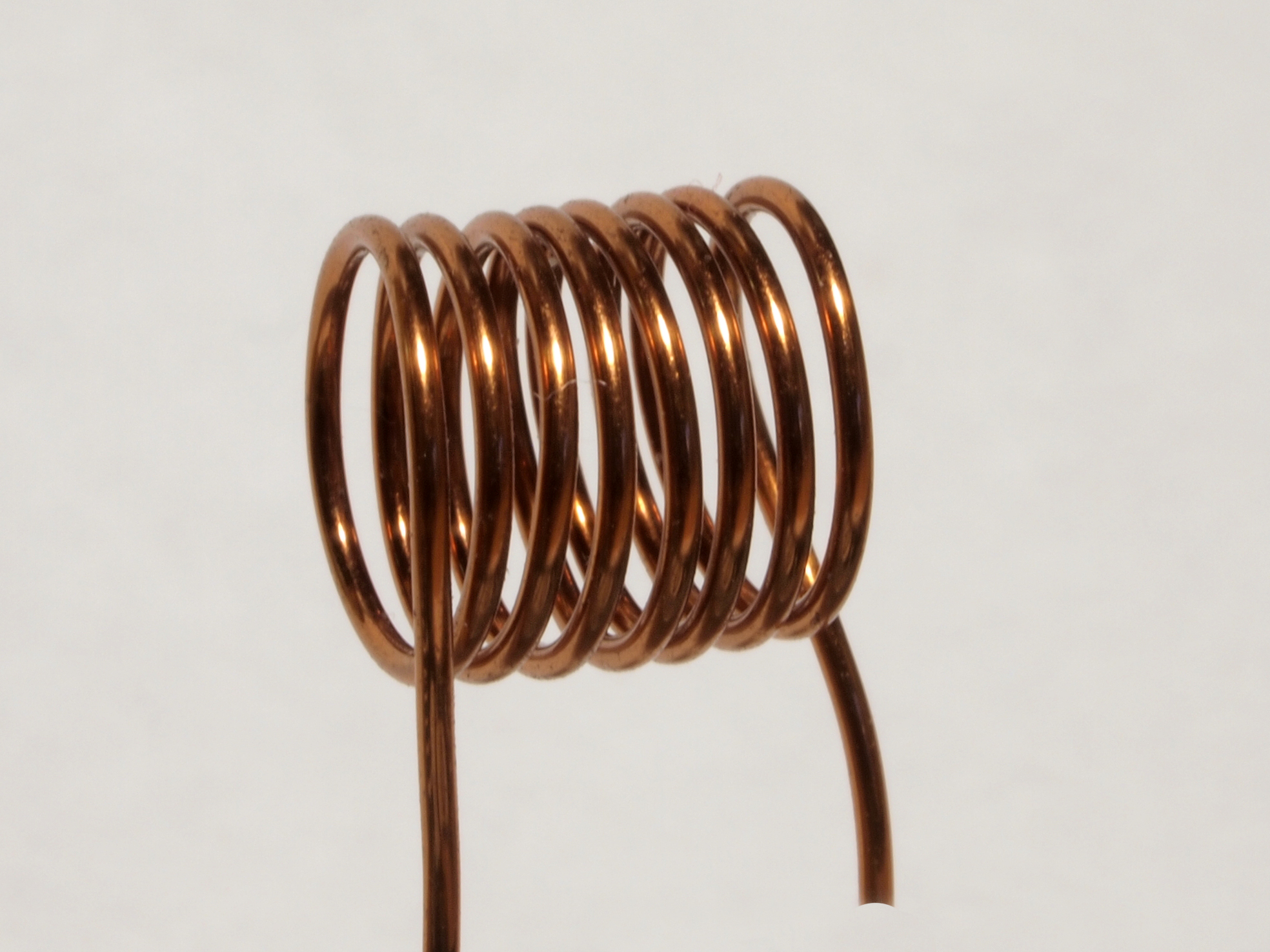
Parts. A rigid, low-loss former sets the tone. Polystyrene, PTFE, ceramic, or even a phenolic tube will do; what matters is low dielectric loss, because the electric field between turns lives partly in the former and a lossy former quietly drains Q. The former here is 0.75 inch (19 mm) outside diameter. The wire is 18 AWG (1.02 mm) enamelled copper — heavy for the current, which is trivial, but heavy on purpose, because thick wire has less resistance and the whole point of an RF coil is to keep the loss down where skin effect is already inflating it. The turns are space-wound, separated by roughly one wire diameter, which suppresses the proximity effect between adjacent turns and lifts Q further at the cost of a longer coil.
Table 1 — Project 1 — An air-core RF coil, about 5 µH
| Item | Value |
|---|---|
| Former OD | 0.75 in (19 mm), low-loss |
| Wire | 18 AWG (1.02 mm) enamelled copper |
| Winding | single layer, space-wound (~1 wire-dia gap) |
| Pitch | ~0.080 in (2.0 mm) per turn |
| Turns | 29 |
| Winding length | ~2.32 in (59 mm) |
| Target L | 5.0 µH |
| Predicted L (Wheeler) | 5.02 µH |
Turns calculation. The workhorse formula from the design volume is Wheeler’s single-layer approximation, in the mixed inch-and-microhenry units it was fitted in:
L (µH) = r² N² / (9r + 10l)
where r is the coil radius in inches measured to the centre of the wire, l is the winding length in inches, and N the number of turns. The former is 0.75 in across, so its radius is 0.375 in; add half the wire diameter (about 0.020 in) and the radius to the wire centre is r ≈ 0.40 in. Space-winding at twice the wire diameter gives a pitch of about 0.080 in per turn, so the length is l = 0.080N. Substituting and setting L = 5.0:
5.0 = 0.40² · N² / (9·0.40 + 10·0.080N)
5.0 = 0.16 N² / (3.6 + 0.8N)
0.16 N² = 18 + 4N
N² − 25N − 112.5 = 0
N = [25 + √(625 + 450)] / 2 ≈ 28.9
Call it 29 turns. Check the result forward: with 29 turns the length is 2.32 in, and Wheeler returns L = 0.16·841 / (3.6 + 23.2) = 134.6 / 26.8 = 5.02 µH — a hair over target, which is exactly where a builder wants to land, because a coil is far easier to trim down by spreading turns than up. The geometry sits squarely in Wheeler’s valid range (the length-to-radius ratio is about 5.8, and the formula is good to roughly one percent for anything longer than about half a radius), so the prediction is trustworthy to the tolerance of the wire and the winding.
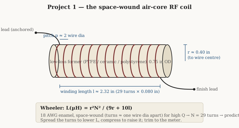
Winding steps. Chuck the former in the winder or a mandrel of matching bore and anchor the start lead — through a small hole drilled near the end, or under a dab of adhesive — so the first turn cannot creep back as tension comes on. Set the traverse, if the machine has a lead-screw traverse, to advance 0.080 in per revolution; on a hand winder without a traverse, lay the turns against a guide or count against a scale and space them by eye against a spacer thread wound alongside and later withdrawn. Keep steady, moderate tension — enough that the turns seat firmly but not so much that 18 AWG bites into a soft former or work-hardens. Wind all 29 turns in one direction, anchor the finish lead the same way as the start, and, once the value is confirmed, lock the whole winding with a thin bead of coil dope or polystyrene cement along one side so the spaced turns cannot shift and detune. The winding-technique volume covers anchoring, spacing threads, and dope in detail; the point here is that a space-wound air-core coil is mechanically floppy until it is bonded, and an unbonded one will not hold its value.
Measure and verify. Read the finished coil on an LCR meter or a nanoVNA at, or near, the frequency it will work at — inductance is not perfectly flat with frequency once the coil’s self-capacitance enters, so measuring at the working frequency is the honest number. Expect something within a few percent of 5.0 µH. If it reads high, gently spread the turns to lengthen l, which lowers L; if it reads low, compress them. A quarter-turn of spreading moves a coil like this by a percent or two, so the adjustment is delicate and fully under the builder’s thumb — this is the great virtue of an air-core coil, that its value is mechanically tunable to the meter. Confirm the self-resonant frequency sits comfortably above the working band (for a coil this size it will be tens of megahertz, set by a fraction of a picofarad of self-capacitance) and note the Q if the instrument reports it; a clean space-wound coil on a good former should show a Q well into the low hundreds across the HF range.
A well-made air-core RF coil is the plainest object in this book and quietly the most satisfying, a bare copper helix that holds its value because the geometry, not a datasheet, defines it.
13.3 Project 2 — A toroidal RF choke, 10 µH on iron powder
Goal. A 10 µH RF choke — a coil whose job is to pass DC or a low-frequency bias while presenting a high reactance to RF, the small series inductor that keeps signal out of a supply line or feeds power to a stage without loading it. A toroid is the natural form: the closed magnetic path keeps the field inside the ring, so the choke barely couples to its neighbours and barely radiates, and the iron-powder material gives enough inductance per turn to reach 10 µH in a few dozen turns on a fingertip-sized core instead of the soup-can of air-core wire the same value would demand.
Parts. The core is an Amidon T68-2: a 0.690 inch (17.5 mm) outer-diameter iron-powder toroid in mix 2 (the red carbonyl-iron material, useful for high-Q resonant and choke work from a few hundred kilohertz to about ten megahertz). Its published inductance index is AL = 57 µH per 100 turns, equivalently 5.7 nH per turn-squared — a real, tolerance-banded number (±5 %) from the manufacturer’s data, not a guess. The wire is 24 AWG (0.51 mm) enamelled copper, thick enough for good Q and thin enough that a single even layer of turns fits around the inner hole.
Table 2 — Project 2 — A toroidal RF choke, 10 µH on iron powder
| Item | Value |
|---|---|
| Core | Amidon T68-2 (iron powder, mix 2) |
| Core OD / ID / H | 17.5 / 9.4 / 4.8 mm |
| AL | 57 µH/100 t (5.7 nH/N²) |
| Wire | 24 AWG (0.51 mm) enamelled |
| Turns | 42, single layer, spread ~330° |
| Target L | 10 µH |
| Predicted L | 10.06 µH |
| Expected SRF | ~30 MHz |
Turns calculation. For a cored coil the design volume’s rule is simply L = AL·(N/100)² in the per-hundred convention, rearranged for turns:
N = 100 · √(L / A_L) = 100 · √(10 / 57) = 100 · √0.1754 ≈ 41.9so 42 turns. Cross-check in the other convention to prove the units cancel: L = 5.7 nH · 42² = 5.7 · 1764 = 10 056 nH = 10.06 µH. ✓ Both forms describe the same physics; writing the units beside the index and watching them cancel is the discipline that keeps a factor-of-ten error from ever leaving the bench.
Two checks decide whether the number is buildable. Does the winding fit? Turns crowd toward the inner hole of a toroid, so the inner circumference sets the single-layer limit: π · 9.4 mm ≈ 29.5 mm of room, and 42 turns of 0.51 mm wire want about 21 mm of that — comfortably one layer, with the turns spread over roughly 330° of the ring and a small gap left between start and finish. Is the self-resonant frequency high enough? A single-layer toroid has little self-capacitance, a couple of picofarads at most; with 10 µH and about 3 pF the SRF lands near 30 MHz, well clear of the few-megahertz band the choke serves. Spreading the winding around most of the core, rather than bunching it, is what keeps that capacitance low — bunched turns face each other and add capacitance, dropping the SRF.
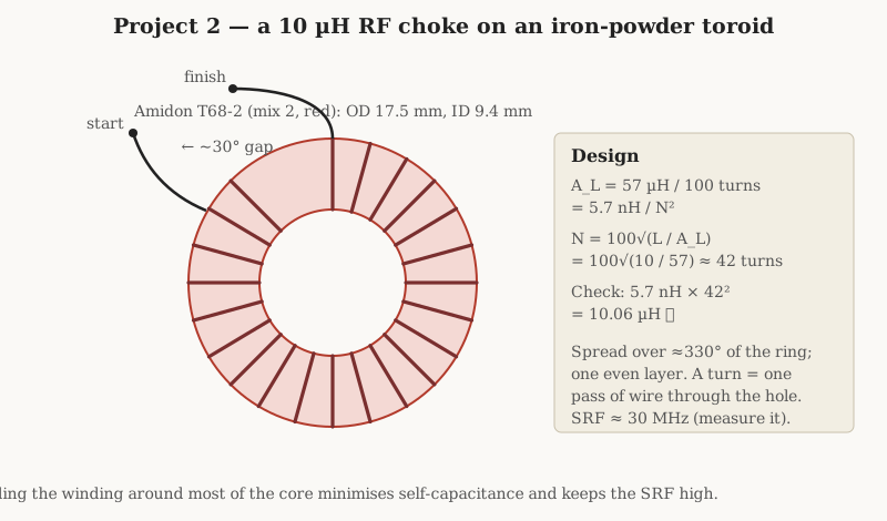
Winding steps. A toroid is wound by threading, not by rotating the core, and the count is the trap for beginners: one turn is one pass of the wire through the centre hole, not one lap around the outside. Cut a generous length of wire — the mean turn is about 15 mm, so 42 turns plus leads wants roughly a metre — and pass it through the hole, snug it against the core, and repeat, keeping firm even tension so each turn lies flat against the ferrite and the previous turn. Advance steadily around the ring, spreading the turns evenly so they end just shy of meeting, leaving that small gap. A toroid winder (a split shuttle pre-loaded with wire, or a hand jig) makes the threading quick; by hand it is simply patient. Anchor nothing until the count is right, then scrape and tin the two leads. The winding-technique volume treats toroid hand-winding, shuttle loading, and the spread-versus-bunch question at length; the essential craft is even tension and an honest turn count.
Measure and verify. Read the choke on the LCR meter: expect 10 µH ± 5 %, the tolerance dominated by the core’s AL band. Because the value is locked in by the core, not the geometry, it is far less tweakable than the air-core coil — a toroid is not trimmed by spreading a single layer more than marginally. If it reads outside tolerance the fix is a turn added or removed, each turn worth about 0.24 µH here (the derivative of AL·N² near N = 42). Confirm the SRF with a sweep and check that the DC resistance is the few tens of milliohms expected of a metre of 24 AWG, which tells the builder there is no partial short or nicked strand.
13.4 Project 3 — A switching-supply power inductor, 100 µH at 3 A
Goal. The output inductor for a buck (step-down) switching regulator: 100 µH, carrying a peak current of 3 A with an RMS of about 2.5 A. This is the energy-bucket inductor of the applications volume — it stores energy in packets each switching cycle and hands it to the load — and it is the first project where the coil can fail two entirely different ways, so the design has to clear two hurdles rather than one. It must not saturate at the current peak (a fast, catastrophic failure that collapses the inductance and usually kills the switch), and it must not overheat from the RMS current’s I²R loss (a slow failure that cooks the insulation). The two demands pull against each other, and the whole reason a power inductor is bigger than its value alone suggests is that it has to satisfy both.
Parts. Energy storage under DC bias demands a gap, because a high-permeability core stores almost no energy in the iron — the energy lives in the gap, where the flux density can run high without the material minding. The core here is a gapped ferrite E-core set, an ETD29/16/10 in N87-class MnZn power ferrite, with an effective magnetic cross-section Ae = 76 mm² and a saturation flux density around 0.39 T when hot (100 °C) — the condition that counts, because B_sat sinks with temperature and a coil fine when cold can saturate when warm. The winding goes on the core’s bobbin, which is exactly where a machine’s lead-screw traverse earns its keep, laying the turns in a neat layer across the bobbin width. The wire is 20 AWG (0.81 mm), sized so the RMS current does not overheat it.
Table 3 — Project 3 — A switching-supply power inductor, 100 µH at 3 A
| Item | Value |
|---|---|
| Core | ETD29/16/10, N87 MnZn power ferrite, gapped |
| Ae / B_sat(hot) | 76 mm² / ~0.39 T |
| Wire | 20 AWG (0.81 mm) enamelled |
| Turns | 16, on the bobbin |
| Gap | ~0.25 mm total (≈0.12 mm per outer leg) |
| Target L / I_pk / I_rms | 100 µH / 3 A / 2.5 A |
| Peak flux B_pk | ~0.25 T (1.6× margin to sat) |
| Stored energy | 450 µJ |
Turns calculation. The design volume’s power-inductor method fixes the peak flux density first and lets it set the turns, rather than guessing turns and hoping. With a gap long enough to dominate the magnetic circuit — true for any useful ferrite gap — the peak flux density in the core is
B_pk = L · I_pk / (N · A_e)
Choosing a target of B_pk = 0.25 T, comfortably below the hot saturation figure, and solving for N:
N = L · I_pk / (B_pk · A_e) = (100e-6 · 3) / (0.25 · 76e-6) = 3e-4 / 1.9e-5 ≈ 15.8Round up to 16 turns — rounding up nudges the flux down, the safe direction. Check the peak flux back: B_pk = (100e-6 · 3) / (16 · 76e-6) = 3e-4 / 1.216e-3 = 0.247 T, about 1.6 times below the 0.39 T ceiling. That margin is the saturation check, and it passes.
With the turns fixed, the gap sets the inductance. From L ≈ µ₀ N² A_e / l_g,
l_g = µ₀ N² A_e / L = (4π×10⁻⁷ · 16² · 76e-6) / 100e-6 ≈ 2.4×10⁻⁴ m ≈ 0.25 mma total gap of about 0.25 mm — a couple of shim thicknesses, or 0.12 mm ground into each outer leg, or a single centre-leg gap of that size. That is the whole design: sixteen turns and a quarter-millimetre of air. The gapped set’s effective inductance index works out to L/N² ≈ 390 nH per turn-squared, the number a manufacturer would print for a core pre-gapped to this value.
The RMS current sets the copper. Sixteen turns on the ETD29 bobbin, mean turn about 53 mm, is roughly 0.85 m of 20 AWG at about 33 mΩ per metre — call it 28 mΩ of DC resistance, so the I²R dissipation at 2.5 A RMS is 2.5²·0.028 ≈ 0.18 W, a gentle warmth the core can shed. Both hurdles cleared: peak flux under saturation and copper loss within budget.
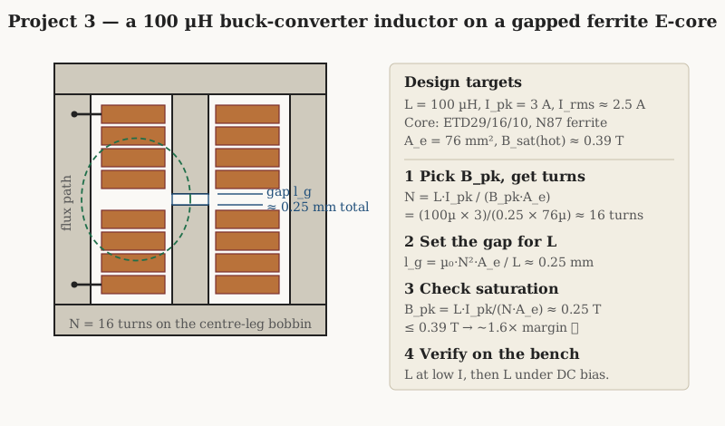
Winding steps. Wind the bobbin off the core, or on a mandrel that mimics it, then assemble the gapped E-halves around it. Set the traverse to lay 16 turns of 20 AWG across the bobbin width in a single even layer if it fits, or two tidy layers if not, keeping firm tension so the turns pack without climbing. Bring the leads out through the bobbin’s slots. Assemble the two core halves with the gap — either a pre-ground centre-leg gap, or a spacer shim of known thickness placed in the flux path (a shim in the outer legs gives half the set gap in each, since the flux crosses two of them; a centre-leg-only gap gives the full length in one crossing, so account for which scheme the core uses). Clamp or bond the halves and, if the supply runs hard, varnish or pot the assembly, both to hold the gap dimension stable and to damp the gap’s tendency to sing at the switching frequency. The winding-technique and machines volumes cover bobbin winding, traverse setup, and gapping practice.
Measure and verify. Two measurements, not one. First read L at low current on the LCR meter: expect 100 µH, adjustable by trimming the gap — widen it to lower L, close it to raise L, since L is inversely proportional to the gap. Then, and this is the measurement that separates a power inductor from a small-signal one, read L under DC bias: feed the coil its rated current from a bench supply while measuring, and confirm the inductance holds up to and beyond 3 A rather than sagging early. A coil that measures 100 µH at zero current but collapses to 60 µH at 3 A has too little gap or too small a core, and the converter built around it will run in a permanent state of near-saturation. The saturation-test methods are in the measurement volume; the design target is a flat inductance out past the peak current with margin to spare.
13.5 Project 4 — A common-mode choke on a ferrite ring
Goal. A common-mode choke for a mains or data line: two windings on one ferrite ring, arranged so that the wanted current — out on one wire and back on the other — passes almost untouched, while common-mode noise — the same direction on both wires at once — meets a high impedance and is choked off. This is the elegant EMI part of the applications volume: because the differential (load) current’s field cancels in the core, the choke can carry real current without saturating, and only the small common-mode component magnetises the ring at all. It is the part on almost every AC mains inlet and every USB or Ethernet pair.
Parts. The core is an Amidon FT82-43: a 0.825 inch (21 mm) outer-diameter ferrite toroid in mix 43, a nickel-zinc material with an initial permeability around 800 and an inductance index AL = 470 mH per 1000 turns, equivalently 470 nH per turn-squared — again a published, tolerance-banded number. Mix 43 is chosen deliberately for its loss: above roughly a megahertz its permeability turns resistive, so the choke’s impedance stops being a clean inductance and becomes a broad, lossy wall that turns common-mode noise to heat across the HF and VHF range, which is exactly the behaviour an EMI part wants. The wire is a pair of 22 AWG (0.64 mm) enamelled conductors, one per line, sized for the load current.
Table 4 — Project 4 — A common-mode choke on a ferrite ring
| Item | Value |
|---|---|
| Core | Amidon FT82-43 (ferrite, mix 43, µᵢ ≈ 800) |
| AL | 470 mH/1000 t (470 nH/N²) |
| Wire | 2 × 22 AWG (0.64 mm) enamelled |
| Turns | 14 per winding (two windings) |
| L per winding | ~92 µH |
| Differential (leakage) L | a few µH |
| Common-mode Z | rises through several hundred Ω by 1 MHz; ~0.5–2 kΩ across HF/VHF |
Turns calculation. Each winding of N turns has, seen by common-mode current, an inductance of AL·N². With 14 turns:
L = 470 nH · 14² = 470 · 196 = 92 120 nH ≈ 92 µH per windingso the common-mode impedance at the low end of the noise band is Z ≈ 2πf·L — about 580 Ω at 1 MHz — and it climbs from there, but not as a pure inductance: as mix 43 goes resistive the impedance broadens into a plateau of roughly half a kilohm to two kilohms across the HF and VHF EMI band, which is the useful working region and the reason a lossy ferrite beats a low-loss one here. The differential inductance the wanted signal sees is a different animal: with the two windings carrying equal and opposite current their fields cancel, so what remains is only the small leakage inductance — a few microhenries at most — that does not couple through the core. That near-invisibility to the load current, and the fact that the load current cannot saturate the ring, is the whole trick.
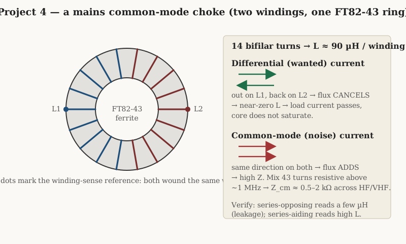
Winding steps. Winding sense is load-bearing here, and it is the classic place to go wrong. The two windings must be wound so that a differential current (in on one, out on the other) drives opposing flux that cancels; wire them wrong and the choke either saturates on the load current or does nothing. In practice the two windings are wound in the same rotational sense around the ring, each occupying its own half — for a mains choke the two halves are kept physically separated, on opposite sides of the ring, to preserve creepage and clearance between line and neutral, rather than twisted together as a tight bifilar pair. Thread 14 turns of the first conductor over one 150°-or-so arc of the ring, then 14 turns of the second over the opposite arc, keeping the turn counts equal so the cancellation is clean. Scrape and tin all four leads and identify them by winding — the dot convention of the figure marks the sense reference. A twisted-bifilar version, the two wires wound together, gives tighter coupling and lower leakage and suits low-voltage data lines, but is avoided on mains for the creepage reason.
Measure and verify. The bench check is a small, satisfying piece of theatre that proves the choke works. Measure one winding alone: expect about 92 µH. Now connect the two windings series-aiding (finish of one to start of the other, so their fields add) and measure: the reading roughly quadruples, because the two coupled windings now act as a single 28-turn coil — this is the common-mode inductance, high, as wanted. Then connect them series-opposing (fields cancel) and measure again: the reading collapses to just the leakage, a few microhenries — this is the differential inductance, low, as wanted. A choke that shows a high series-aiding inductance and a low series-opposing one is wound correctly; if the two readings are similar, the windings are mismatched or the sense is wrong. On a nanoVNA the common-mode impedance can be swept directly to confirm the lossy plateau across the noise band.
13.6 Project 5 — A tapped inductor for antenna matching
Goal. A tapped coil — one winding with several connection points brought out along its length, so a switch or clip can select different inductance values from a single part. The example is a matching inductor for a simple antenna tuner or L-network, where different bands want different inductances and a tapped coil covers them without a box full of separate parts. The project’s real purpose in this volume is to demonstrate tapping: how a tap is computed, brought out, and terminated, a technique that carries straight over to matching networks, autotransformers, and the multi-tap windings of the transformer dive to come.
Parts. The core is an Amidon T68-2 again — the same red iron-powder ring as Project 2, AL = 57 µH per 100 turns (5.7 nH/N²) — wound this time with 30 turns of 24 AWG and tapped at three points. The taps sit at 10, 20, and 30 turns, and because inductance goes as the square of the turns, the three positions give a useful spread of values from a fraction of a microhenry to several.
Table 5 — Project 5 — A tapped inductor for antenna matching
| Tap | Turns | L = 5.7 nH · N² |
|---|---|---|
| A | 10 | 0.57 µH |
| B | 20 | 2.28 µH |
| C (finish) | 30 | 5.13 µH |
Turns calculation. Each tap is just the inductance-index rule evaluated at the tap’s turn count. From the start of the winding to tap A at 10 turns: L = 5.7 nH · 10² = 0.57 µH. To tap B at 20 turns: 5.7 · 400 = 2.28 µH. To the finish at 30 turns: 5.7 · 900 = 5.13 µH. The square law is the useful part — doubling the turns quadruples the inductance — so a handful of taps spans a wide range, and the same reasoning lets a builder place a tap wherever a particular value is wanted by solving N = √(L/AL) for that value and counting to it during winding.
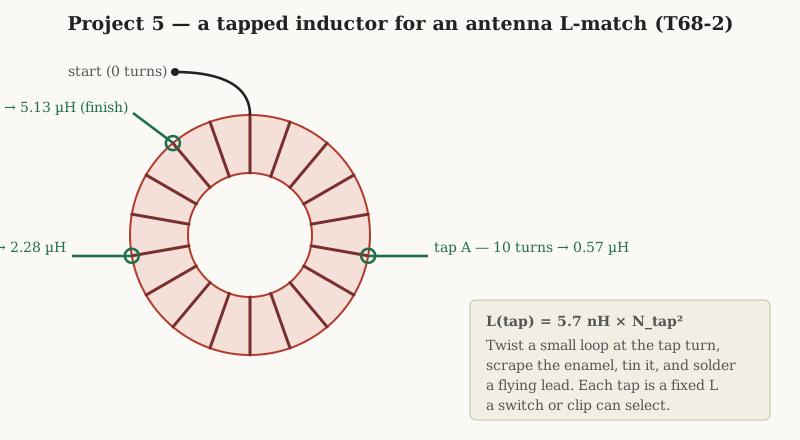
Winding steps. Wind as for Project 2 — even tension, single layer spread around the ring — but pause at each tap turn to bring the tap out. The neat way is to twist a small loop of the winding wire itself at the tap point without cutting it: give the wire a couple of twists into a short pigtail a centimetre long, then carry on winding. When all 30 turns are down, scrape the enamel from each twisted loop, tin it, and solder a flying lead to it; the winding is continuous copper, and the taps are simply places where a connection is made to it. Counting is the discipline: mark or log the turn number as each tap loop is formed, because a tap one turn off throws its value by the derivative of the square law. The winding-technique volume covers tapping, loop-forming, and mid-winding terminations; the same method layer-wound on a bobbin — pausing between layers to bring a tap out to a terminal pin — is how a mains or audio choke is tapped, and how a transformer’s taps are made.
Measure and verify. Measure each tap against the common start with the LCR meter: expect 0.57, 2.28, and 5.13 µH at taps A, B, and C, each within the core’s ±5 % band. A tap reading well off its neighbours in the wrong direction usually means a miscount or a tap loop soldered to the wrong turn; re-count against the log. Confirm continuity from the start through each tap to the finish, and that no tap loop has shorted to an adjacent turn where its enamel was scraped — the ring test of the measurement volume catches a shorted turn if one is suspected.
13.7 Troubleshooting: when the meter disagrees
Every failure in coil winding announces itself the same way — the meter reads something the design did not ask for — and the diagnosis is a short list of usual suspects. The following gathers the ones common to the projects above, each with its fix.
Inductance too high or too low. This is the everyday miss, and the cause depends on the type. On an air-core coil the value is geometry, so a high reading means the turns are too close (compress-free, so spread them to lengthen the coil and lower L) and a low reading means they are too spread (compress them). On a cored coil the value is the inductance index times turns-squared, so the fix is a turn added or removed — and if the count was right, suspect the core: iron-powder and ferrite indices carry a five-to-twenty-percent tolerance, and a batch on the low edge of AL simply needs a turn or two more. On a gapped power core, a high or low inductance is almost always the gap — too small a gap over-inducts, too large under-inducts — so trim the shim. Confirm the count before blaming the core; a miscount masquerades as everything.
Low Q. A coil that tunes but rings poorly is losing energy somewhere. At radio frequency the usual thieves are thin wire (skin effect inflating the resistance — go heavier, or Litz below a few megahertz), bunched turns (proximity effect — space them), a lossy former or a soggy dose of the wrong dope (dielectric loss — use a low-loss former and a proper coil cement), and, on a cored coil, the core material itself run outside its useful frequency band, where core loss dominates. Match the core mix to the frequency: an iron-powder mix chosen for the wrong decade of the spectrum will have a mediocre Q no winding can rescue.
Self-resonant frequency too low. If the coil’s SRF sits too close to the working frequency the inductance is no longer flat and the part misbehaves. The culprit is self-capacitance, and self-capacitance comes from turns facing each other: too many layers, or bunched turns on a toroid, or a multilayer winding wound as a solid block rather than progressively. The fixes are the geometry ones from the winding volumes — spread a toroid’s turns around the ring, break a multilayer coil into progressive or universal (honeycomb) sections so successive layers do not face at full voltage, and never wind more layers than the value truly needs.
A shorted turn. A coil that reads far too low, or that a ring test shows dead — struck with a step and refusing to ring, its energy dumped instantly into the short — has a turn shorted to its neighbour, usually where enamel was nicked during winding or scraped for a tap and left touching. There is no repair; find the short (a bright spot, a scrape, a tap loop kissing an adjacent turn), and if it cannot be cleanly separated, unwind and rewind with fresh wire and more care at the terminations. The ring or flyback test of the measurement volume is the fast way to catch a shorted turn that a plain inductance reading might only hint at.
A coil that saturates. A power inductor whose inductance is fine at low current but collapses under load has too little gap or too small a core for its peak current — the flux is reaching B_sat at the top of each cycle. The cure is more gap (which lowers the peak flux for the same turns, at the cost of inductance, so add turns to recover it) or a larger core with more cross-section. This is why the DC-bias measurement matters: a coil that passes at zero current and fails at rated current would sail through a naive bench check and then die in the converter. Rate the core for the fault current, not just the normal peak.
A floppy coil. A space-wound air-core coil or a lightly-held toroid that drifts in value with handling or vibration was never mechanically finished. The value of an air-core coil is its geometry, so a winding that can move is a value that can move. Bond it: a bead of polystyrene cement or coil dope along a space-wound solenoid, a dab of adhesive anchoring a toroid’s leads and its winding gap, or a dip-and-bake varnish for anything that will see vibration. A coil is not done when it measures right once; it is done when it will still measure right after it has been dropped in a parts drawer.
13.8 From coils to transformers
Five projects, one method: pick the core or former for the job, compute the turns from Wheeler or the inductance index, wind on the machine with honest tension and an honest count, and finish at the meter with the design’s number as the target. The same winders, the same magnet wire, the same iron-powder and ferrite cores, and every technique in these projects carry directly into the next discipline, because a transformer is nothing but two or more coils made to share a field on purpose. The toroid hand-wound for Project 2 becomes a wideband RF transformer when a second winding is threaded alongside it; the gapped bobbin of Project 3 becomes a flyback transformer when a secondary is added; the tap of Project 5 becomes the turns-ratio of an autotransformer; and the two-winding, winding-sense discipline of the common-mode choke is exactly the discipline of getting a transformer’s phasing right. The coming Transformers and transformer winding dive picks up precisely there — with the winders still warm — and turns the craft of winding one coil into the craft of winding several that talk to each other.
Comments (0)