Coils and Coil Winding · Volume 6
Types of Coils and Winding Geometries
6.1 The shape is the circuit
An inductor is, at bottom, a length of wire arranged so that its own magnetic field threads back through itself. That sounds like a purely mechanical fact — wind the wire, get the coil — but the arrangement is where the electrical engineering hides. The same twenty metres of magnet wire can be laid down as a long thin single-layer solenoid, packed into a stubby multilayer bobbin, criss-crossed into a honeycomb, or threaded around a ferrite ring, and each of those coils will have a different inductance, a different self-capacitance, a different self-resonant frequency, a different quality factor, a different external field, and a different price to manufacture. The geometry is not decoration on top of the inductance; the geometry is the inductance, and it sets every parasitic that the earlier volume on the real (non-ideal) inductor spent its pages worrying about.
That is the organising idea of this volume. Where the real-inductor volume asked what goes wrong — distributed capacitance, self-resonance, the collapse of Q with frequency — this one answers what you do about it, and the answer is almost always “choose a different winding geometry.” The winding-machines volume and the winding-technique volume that follow are about how you physically lay a given geometry down — the traverse mechanism, the tension, the count, the toroid held in the fingers. This volume is about what the classic geometries are and why each one exists. A coil’s shape is a set of deliberate trade-offs among inductance density, self-capacitance, Q, leakage field, mechanical ruggedness, and manufacturability, and a designer who knows the menu can reach for the right shape instead of winding the first thing that fits the bobbin.
6.2 The single-layer solenoid
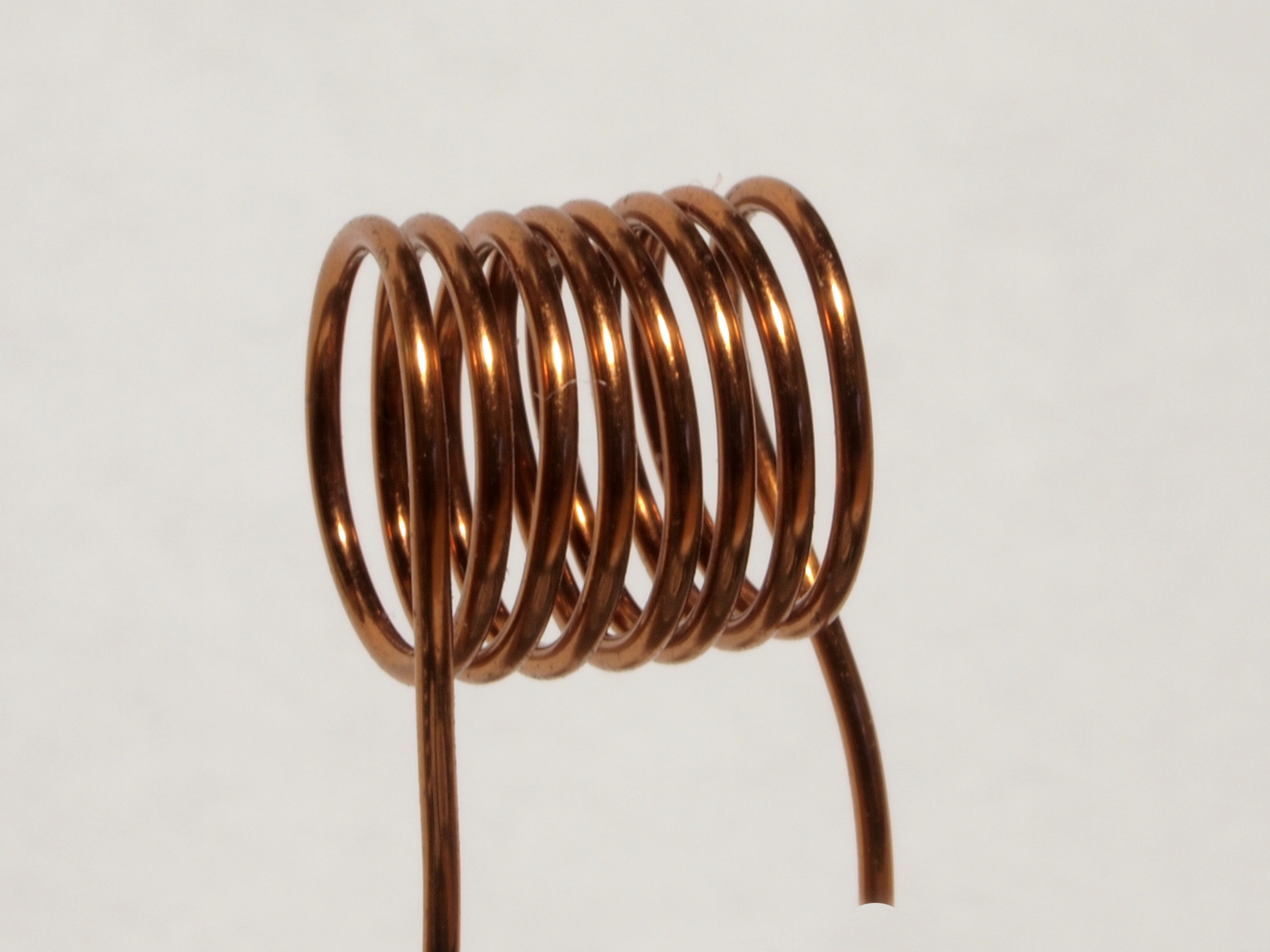
The solenoid — a single helical layer of wire wound on a cylinder, whether that cylinder is a plastic coil form, a ceramic rod, a ferrite slug, or nothing but air — is the coil that every textbook draws and every other geometry is measured against. Its inductance rises with the square of the number of turns and with the enclosed cross-sectional area, and falls as the winding is stretched longer; the design volume gives Wheeler’s formulas for turning those dependencies into a turns count. What matters here is why the single layer is so good electrically, because that goodness is the reason the shape survives in every high-frequency circuit despite being the least compact way to store a given inductance.
The virtue is low self-capacitance. In a single layer, the only turns that sit close enough to store appreciable charge between them are immediate neighbours, and immediate neighbours differ in potential by just one turn’s share of the coil voltage — a small number. Small voltage across each little inter-turn capacitance means little stored charge, and because those tiny capacitances are effectively strung in series down the length of the winding, the total distributed capacitance seen at the terminals is modest. Every turn, moreover, faces mostly air (or a thin former) rather than another copper turn, so there is little dielectric to add loss or capacitance. The upshot is a high self-resonant frequency and, because Q is degraded by both loss and by the way self-capacitance drags the coil toward resonance, a high quality factor at radio frequencies. When an RF designer wants the highest Q obtainable in a given volume, the single-layer solenoid — often spaced, often on a low-loss ceramic former — is the default, and it has been since the first spark-era tuning inductors.
6.2.1 Close-wound versus spaced
Within the single-layer family the winder still has a choice: lay the turns touching, or leave a gap between them.
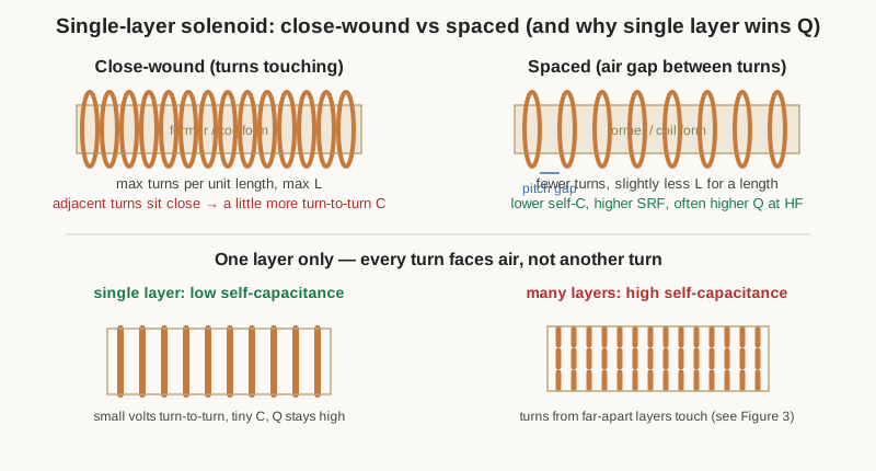
Close-winding — turns hard against one another, insulated only by the wire’s enamel — packs the most turns into a given length and so wrings the most inductance out of a coil form. It is the natural choice when inductance density matters more than the last few points of Q: audio chokes, lower-frequency RF, the secondary of a slug-tuned can. Its cost is a slightly higher turn-to-turn capacitance and a stronger proximity effect, the magnetic crowding of current described in the magnet-wire volume, both of which nibble at Q as frequency climbs.
Spacing the turns — a wire-diameter of air between each, held by the pitch of the winding machine’s traverse or by a grooved former — trades a little inductance for a lower self-capacitance and a weaker proximity effect. At VHF and above, where a coil may be only a handful of turns, spacing is nearly universal: it lifts the self-resonant frequency, raises Q, and makes the inductance less sensitive to the dielectric of the former. The penalty is a longer coil for the same turns and a more delicate structure, since spaced air-wound coils have nothing but their own stiffness holding the pitch. The technique volume covers how the traverse pitch and a little lacquer keep a spaced coil honest.
6.2.2 Length, diameter, and taps
A solenoid’s proportions matter as much as its turn count. A long, thin coil leaks much of its flux out the sides before it can link all the turns, so it is an inefficient use of wire; a short, fat coil links its flux tightly but runs out of winding length. There is a classic optimum, first worked out in the coil-design literature and repeated in every radio handbook since, at which a fixed length of wire yields the maximum inductance — a coil whose diameter is roughly two to two and a half times its length. Coils are rarely built exactly at that optimum, because other constraints (the available former, the need for high Q, the space in the chassis) pull the proportions around, but it explains why high-Q RF solenoids tend to look stubby rather than pencil-thin. The design volume gives the numbers.
The single layer also makes tapping trivial. Because every turn is exposed on the outside of the coil, a tap — a wire soldered to a turn partway along — can be brought out anywhere to divide the inductance, match an impedance, or provide an autotransformer ratio. Tapped solenoids are the backbone of antenna matching networks and of the tuned circuits in old tube radios, where a tap a few turns up from the cold end feeds a low-impedance point without a separate transformer. Multilayer coils can be tapped too, but only at a layer boundary that happens to surface, which is one more reason the single layer stays popular where taps are wanted.
6.3 Multilayer and bobbin windings
When a design needs many turns — a large inductance, a mains-frequency choke, the primary of a transformer — a single layer becomes absurd: the coil would be metres long. The answer is to wind layer upon layer, back and forth across a bobbin, stacking turns radially until the required count fits in a compact window. This is the workhorse geometry of power magnetics and of any inductor where inductance density beats Q, and it is what the great majority of wound components actually are.
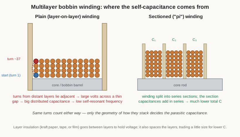
The compactness comes at an electrical price, and the price is capacitance. Picture the winding sequence: the wire fills the first layer left-to-right, climbs to the second layer and comes back right-to-left, climbs again, and so on. Now look at two turns that lie against each other across a layer boundary near one end of the coil. One of them was laid down early in the winding; the one directly above it was laid down a full layer’s worth of turns later, or a whole traverse away. They are physical neighbours but electrical strangers, separated by many turns’ worth of voltage — and that large potential difference sits across the thin gap of enamel and air between the layers. Large voltage across a small gap is exactly the recipe for stored charge, so the layer-to-layer capacitance of a plain multilayer winding is far higher than anything a single layer produces. That distributed capacitance resonates with the inductance at a low self-resonant frequency, which is why multilayer bobbin coils are creatures of low frequency: superb for a 50/60 Hz filter choke, hopeless as a VHF tuning inductor.
Between the layers the winder puts layer insulation — a wrap of kraft paper, polyester film, or tape — for two reasons. The obvious one is voltage: the film has to hold off the accumulated potential between layers, and in a transformer or a high-voltage choke that potential can be large enough to arc through bare enamel. The subtler one is that the insulation spaces the layers apart, and a slightly larger gap means slightly less capacitance, so layer insulation is a lever on self-resonance as well as a safety measure. The winding-technique volume treats interleaving and layer insulation in detail, because doing it well is most of what separates a quiet transformer from a buzzing one.
6.3.1 The pi (sectioned) winding
The classic trick for keeping many turns without the capacitance is to refuse to build one tall pile and instead break the winding into several short, narrow sections wound side by side along the core — the pi winding, so called because each fat little section resembles the shape of a mince pie, and also called a sectioned or slot-wound choke. Each section is a small multilayer pile, so each has its own capacitance, but the sections are connected in series, and capacitances in series add reciprocally — the total is smaller than any one of them. Just as importantly, the sections are physically separated by the flanges of the bobbin, which spaces the high-voltage ends apart and cuts the section-to-section capacitance. The result is a coil that keeps a large inductance but pushes its self-resonant frequency up by a large factor compared with the same turns wound as one pile.
The pi winding is the RF-choke geometry. A radio-frequency choke has to present a high impedance across a wide band while carrying a bias or supply current, and a plain multilayer coil would self-resonate somewhere in the middle of that band and turn into a capacitor. Winding it as three, five, or seven pi sections, sometimes with different turn counts so their individual resonances are staggered rather than piled at one frequency, spreads the resonances out and keeps the impedance high and useful across the whole range. Any bench drawer of small RF chokes is mostly rows of these multi-humped little coils.
6.4 The low-capacitance RF geometries
Before ferrite and before the pi-wound choke was refined, early radio faced a hard problem: it needed coils of substantial inductance and high Q at frequencies where a plain multilayer coil’s self-capacitance was ruinous. The industry’s answer was a family of ingenious winding geometries that all attack the same enemy — turn-to-turn capacitance — by the same means: stop the turns from lying parallel to one another.
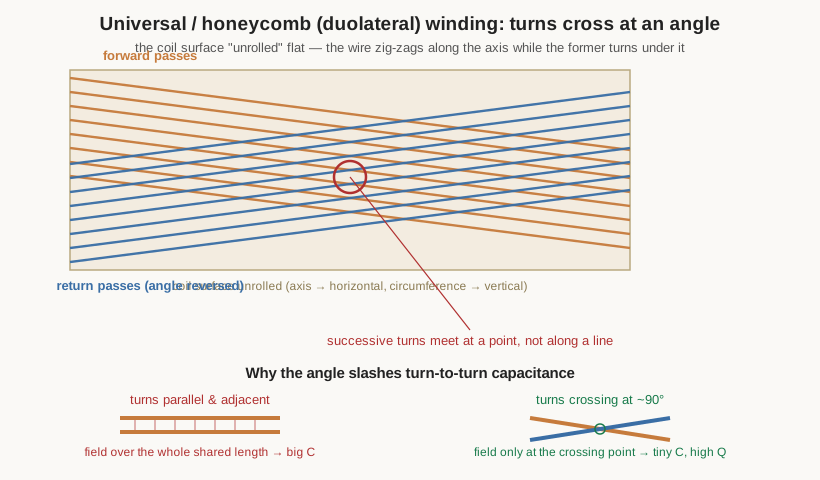
The physics is worth stating plainly, because it is the whole reason these coils exist. Two wires that run parallel and close for some length form a capacitor whose value grows with that shared length — the electric field spreads all along the gap between them. But if the two wires instead cross at an angle, they are close only at the single point where they intersect; a millimetre either side of the crossing they are diverging into air. The field clusters at the crossing and nowhere else, so the capacitance between those two turns collapses to a tiny fraction of what parallel running would give. Cross every turn over its neighbours at a steep angle and the coil’s total distributed capacitance falls dramatically, its self-resonant frequency climbs, and its Q at radio frequencies rises with it. The steeper the crossing — as near to a right angle as the machine can manage — the smaller the residual capacitance.
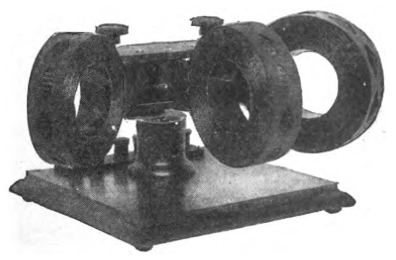
The universal winding, and its early hand-built cousins the honeycomb and duolateral coils, put this idea into a machine. As the former rotates, the wire guide traverses back and forth along the axis much faster than in an ordinary layer winding, laying the wire down as a steep diagonal that reverses direction at each end of the traverse. Successive passes cross the previous ones at a large angle, building up a self-supporting lattice — the honeycomb look — in which almost no two turns run parallel. Early-radio catalogues sold plug-in honeycomb and duolateral coils in graduated inductances so a set-builder could swap tuning ranges, and the geometry remains in use wherever a compact, high-Q RF inductor of substantial value is needed: the coils in old superheterodyne IF transformers, in RF chokes, and in modern wire-wound RF inductors are universal-wound for exactly this reason. The winding-machines volume describes the cam-and-gear mechanism that generates the reversing traverse, because a universal winder is a distinctly different machine from a plain layer winder.
6.4.1 Basket-weave and spiderweb
Two older, simpler geometries reach the same goal by hand, using a slotted or pegged former instead of a clever machine.
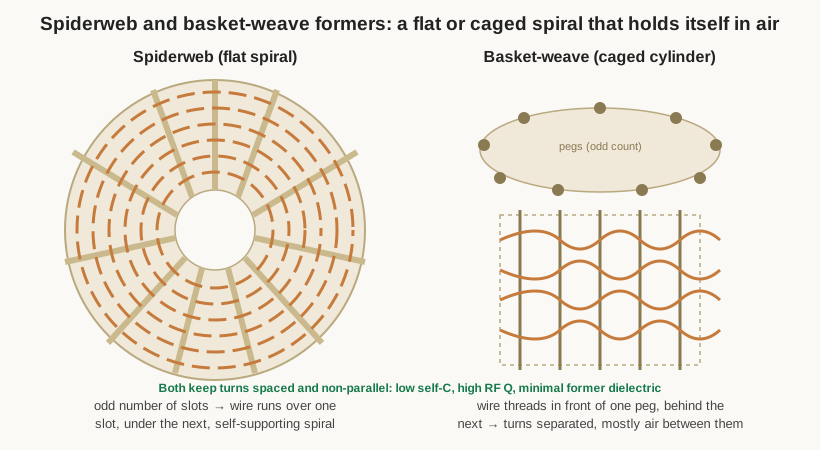
A spiderweb coil is a flat spiral wound on a disc with an odd number of radial slots cut into its rim. Because the slot count is odd, the wire passes over the front of one slot and under the back of the next, alternating face each time it comes around, so it weaves through the former and holds itself as a rigid flat spiral with air between the turns. A basket-weave coil does the same trick on a cylinder: an odd number of pegs or ribs stand in a circle, and the wire threads in front of one and behind the next, building a caged, basket-like tube of spaced, criss-crossing turns. In both, the turns are held apart and never run parallel for any length, so — like the honeycomb — the distributed capacitance is small and the Q high, and because the former is mostly air with only thin ribs of dielectric, there is little lossy material near the field. These were the high-performance tuning and coupling coils of the crystal-set and early-valve era, and they are still wound by hobbyists and by builders of high-Q circuits who value a coil that needs no plastic bobbin.
6.4.2 Bank winding
One more classic deserves a mention because it attacks the multilayer capacitance problem from a different direction. In bank winding (sometimes “banked” winding), the winder deliberately orders the turns so that turns which are adjacent in the winding sequence also end up physically adjacent, building the coil up in a stepped, narrow-front pattern a few layers deep rather than completing each full layer before climbing. Because neighbours in space are also neighbours in the sequence, the voltage between any two touching turns stays small — one or two turns’ worth — even though the coil is several layers thick. That keeps the inter-turn capacitance low while still achieving a multilayer turn count, which is why bank winding was used for RF coils that needed more inductance than a single layer could give without the self-resonance penalty of a plain pile.
6.5 Toroidal windings
Bend the core into a closed ring and wind the wire around the ring’s cross-section, each turn passing up through the central hole and back around the outside, and the result is a toroid — geometrically the most self-contained coil there is.
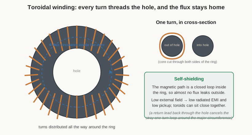
The toroid’s defining electrical property is its low external field. In a solenoid, the flux must leave one end of the coil, travel back through the surrounding air, and re-enter the other end; that return path sprays magnetic field into the neighbourhood, where it radiates interference and couples into anything nearby. In a toroid the magnetic circuit is a closed loop that never leaves the ring: the flux runs around inside the high-permeability core, whose reluctance is so much lower than the surrounding air that the field lines have no incentive to stray outside. The external field of a well-wound toroid is small and falls off steeply with distance, which makes the toroid self-shielding — it radiates little EMI and picks up little from its surroundings, so toroids can be packed close together and placed near sensitive circuitry in ways a solenoid never could. That, together with the efficient use of core material (a short, fat, closed magnetic path gives a high inductance per unit of core volume and per turn), is why the toroid dominates power-supply chokes, common-mode chokes, and high-inductance RF chokes.
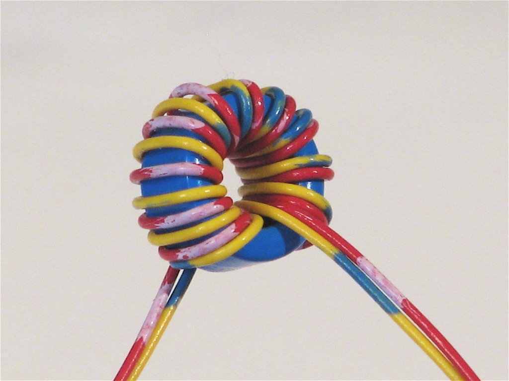
The price of all that virtue is paid at winding time, and it is the reason the toroid gets its own treatment in the winding-technique volume. There is no way to spin wire onto a closed ring the way a lathe spins it onto a bobbin, because the wire has to pass through the hole on every single turn. Toroids are wound either by hand — a length of wire pre-cut, threaded through the ring again and again, each pass pulled snug — or on a specialised toroid winder that first loads a shuttle or a split ring with wire and then feeds it through the core, a machine the machines volume describes because it works nothing like an ordinary bobbin winder.
How the turns are laid around the ring is itself a geometric choice. A single-layer, distributed winding — turns spread evenly all the way around the circumference — gives the lowest leakage and the lowest stray capacitance, and is the standard for RF and common-mode work; crowding all the turns into one arc of the ring wastes the geometry’s self-shielding and raises capacitance. Winding can proceed progressively around the ring in one direction, or be back-wound (returning part-way) to place a second winding or to reduce capacitance. One subtlety trips up the unwary: a winding that marches once around the major circumference of the ring also forms, in effect, a single large turn in the plane of the toroid, and that stray one-turn loop can radiate and pick up field, undoing some of the self-shielding. The standard fix is to bring the finish lead back through the centre of the ring so it retraces the major circumference in the opposite sense, cancelling that phantom turn — a detail the technique volume returns to, but a geometric one worth flagging here.
6.6 Chokes
A choke is not a distinct kind of coil so much as a job a coil is asked to do: present a high impedance to alternating current — either broadband, or over a chosen band — while passing direct current or a lower frequency with little loss. The word comes from the coil’s action of “choking off” the AC. Because reactance rises with frequency, any inductor chokes high frequencies more than low ones; what makes a coil a choke is that it is designed and named for that blocking role rather than for tuning or energy storage, and its geometry is chosen accordingly.
Radio-frequency chokes (RFCs) block RF while passing DC or audio — feeding supply voltage to a stage without letting the signal escape up the supply line, for instance. Their whole design problem is to stay inductive across a wide band without self-resonating in the middle of it, which is precisely why they are so often pi-wound into staggered sections, or wound on a ferrite or iron-powder core whose permeability adds inductance without adding much length. Power and filter chokes block the ripple and hum of a rectified supply while passing the DC load current; they need a large inductance and must carry that DC without the core saturating, so they are typically multilayer or bobbin-wound on a gapped iron or powdered-iron core — the air gap, covered in the core-materials volume, is what lets them hold DC bias without losing their inductance. The same coil that would be a poor RF choke (many turns, high capacitance, low self-resonance) is an excellent power choke, because at 100 or 120 Hz its self-capacitance is irrelevant and its large inductance is exactly what filters the ripple. Geometry follows the job.
6.7 Common-mode chokes
The common-mode choke is the cleverest use of winding geometry in the whole catalogue, because it uses the direction of the windings to make one component behave two completely different ways toward two kinds of current on the same pair of wires.
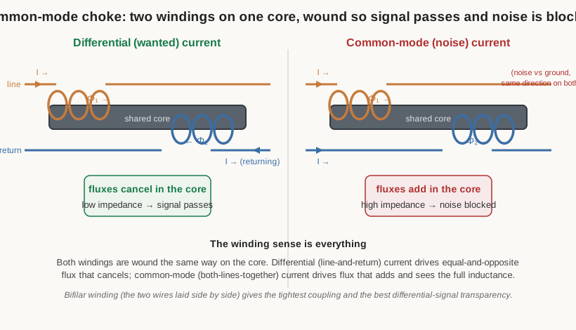
Two windings share one core — usually a ferrite ring — and they are wound in the same sense, so that current entering both windings “the same way” produces flux that adds. Now consider the two kinds of current that flow on a signal or power pair. The wanted current is differential: it flows out along one conductor and back along the other, equal and opposite. In the choke, those opposite currents drive equal and opposite fluxes that cancel in the shared core, so the core stores almost no energy, the differential inductance is tiny, and the wanted current sails through almost unimpeded. The unwanted current is common-mode: noise, referenced to ground, that flows the same direction on both conductors at once. Common-mode current drives flux from both windings that adds, so the core presents its full, large inductance to that current and chokes it off. One component, transparent to the signal and a brick wall to the noise, and the difference is entirely in the winding sense. This is the workhorse of mains input filters, switch-mode power-supply EMI suppression, and the protection of USB, Ethernet, and other data lines, where it kills common-mode noise without distorting the differential data.
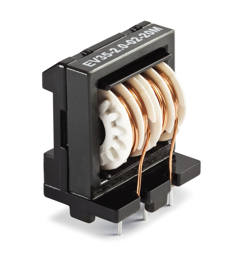
Because the differential performance depends on the two fluxes cancelling as completely as possible, the two windings want the tightest possible magnetic coupling — any flux that fails to cancel appears as leakage inductance that does impede the wanted signal. That is why common-mode chokes are so often bifilar-wound, the two wires laid down side by side as a pair so that every turn of one sits right against the matching turn of the other. Where a data line demands the choke be transparent to fast differential edges, bifilar winding’s low leakage inductance is what keeps the signal clean. Getting the winding sense right is not optional: reverse one winding and the choke’s behaviour toward common and differential current swaps, turning a noise filter into a signal killer.
6.8 Bifilar and multifilar windings
Bifilar winding — laying two wires together and winding them as one — deserves its own note, because tight coupling between windings is a goal in its own right, not just a means to a good common-mode choke. When two conductors are wound as a bonded or twisted pair, every turn of one is magnetically as close to the flux as every turn of the other, so the coupling coefficient approaches unity and the leakage inductance between them approaches zero. That near-perfect coupling is exactly what a balun (a balanced-to-unbalanced transformer) or a broadband RF transmission-line transformer needs, and it is why such devices are wound bifilar — often as a twisted pair whose twist rate sets a controlled characteristic impedance — on a ferrite core. Trifilar and higher multifilar windings extend the idea to three or more wires for multi-winding transformers and more elaborate baluns, all trading the extra winding labour for coupling so tight the windings behave almost as one. The transformer volume that follows this deep dive leans on bifilar and multifilar geometry heavily, since tight coupling is the essence of a good transformer; here it is enough to note that when the design goal is coupling rather than isolation, winding the wires together is the geometry that delivers it.
6.9 Tapped and variable geometries
Two families of geometry exist to make a coil’s value adjustable rather than fixed, and both are covered in depth in the specialty-and-variable volume; they are noted here so the geometric menu is complete.
Tapped coils, mentioned above for the solenoid, bring out one or more connections partway along the winding. A tap divides the inductance into series portions and lets a single coil serve as an autotransformer or an impedance-matching device — the tuned circuit taps of a radio, the matching taps of an antenna coupler, the taps of a rotary band switch that reconfigures a transmitter’s tank coil. The geometry is simply a deliberately accessible turn.
Variable coils change their inductance mechanically. A slug-tuned or permeability-tuned coil holds its turns fixed and moves a threaded ferrite or powdered-iron core in and out of the winding; sliding the high-permeability slug deeper raises the inductance, and this is how the IF and oscillator coils of nearly every superheterodyne radio are aligned. A roller inductor or variometer changes the inductance by mechanical means at the winding itself — a roller contact that taps a long solenoid at a continuously variable point, or a rotating inner coil whose field aids or opposes an outer one. These are the big adjustable coils of antenna tuners and transmitters. In every case the geometry is chosen so that a mechanical motion maps smoothly onto a change in inductance.
6.10 Air-core versus cored geometry
Running through all of the above is the choice the core-materials volume laid out: whether to wind on air (or a non-magnetic former) or on a magnetic core. It is worth restating here as a geometric decision, because it changes what a coil of a given inductance looks like. A magnetic core multiplies the inductance of a given winding by its permeability, so a cored coil reaches a target inductance with far fewer turns and a far smaller size than an air-core coil — the reason a fingertip-sized ferrite toroid can replace a fist-sized air solenoid. The designer accepts a core, and the smaller coil it brings, until one of the core’s vices makes it unacceptable: the non-linearity and saturation of the core under high current or high flux, the core loss that climbs with frequency and wastes power as heat, or the temperature and manufacturing sensitivity of the material. Where linearity must be perfect, where the current is large enough to saturate any affordable core, or where the frequency is high enough to make core loss prohibitive, the designer skips the core and accepts a bigger, air-wound coil — which is exactly why high-power RF tank coils and the highest-Q VHF inductors are large single-layer air solenoids rather than compact cored parts. Geometry and core are two knobs on the same instrument, and they are turned together.
6.11 Matching the geometry to the job
The winding geometries in this volume are not a historical parade; they are a working menu, and the whole point of knowing them is to reach for the right one. A few rules of thumb close the volume.
For the highest Q at radio frequency, wind a single-layer solenoid, spaced, on a low-loss former — or, where a compact high-Q coil of larger value is needed, a universal/honeycomb, basket-weave, or spiderweb winding whose crossing turns keep the self-capacitance low. For a high-inductance RF choke that must stay inductive across a band, break the winding into pi sections so the section capacitances series-add and the resonances stagger. For low-EMI power inductors and filter chokes, and for the most efficient use of core material, wind a toroid, whose closed magnetic path keeps the flux inside and the interference outside — and gap the core if it must hold DC bias. For noise suppression on a signal or power pair, wind a common-mode choke, two windings in the right sense on a shared core, so the signal passes and the common-mode noise is blocked. And when the design goal is tight coupling — a balun, a transmission-line transformer, the low-leakage version of a common-mode choke — wind the wires together, bifilar or multifilar, so the windings behave as one. The fill factor that decides how much copper each of these geometries can pack into its window is the wire volume’s subject; the turns count that hits a target inductance is the design volume’s; the machines and the hands that lay these shapes down are the next two volumes’. This one has supplied the vocabulary of shapes and, more importantly, the reason each shape exists — so that when a coil is called for, its geometry is chosen on purpose.
Comments (0)