Coils and Coil Winding · Volume 3
A Short History of the Coil
3.1 From a twitching compass to the wound toroid
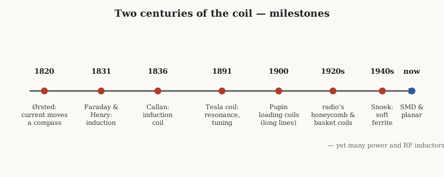
A coil is such a plain object — turns of insulated wire around some kind of former — that it is easy to forget it had to be invented, or rather discovered, one careful experiment at a time. Nobody woke up one morning with the idea of an inductor. The concept had to be assembled out of a chain of surprises that ran for the better part of a century: that a current can push a compass needle, that a changing current can conjure a voltage in a neighbouring wire, that a coil resists changes in its own current, and finally that a well-shaped pile of wire and iron can store energy, transform voltage, and pick one radio station out of the sky.
This volume tells that story. It is a companion to the theory volume, which explains what an inductor does, and to the core-materials and winding-machines volumes, which explain how a good one is made. Here the aim is narrative: to follow the coil from a Danish lecture bench in 1820 to a surface-mount part smaller than a grain of rice, and to keep the engineering honest along the way. The satisfying part, for anyone who has ever sat at a winding machine counting turns, is that the oldest idea in the story — wrap enough insulated wire around a core and remarkable things happen — is exactly the idea still at work on the bench today.
3.2 The electromagnetic dawn: Ørsted and Ampère, 1820
For most of the eighteenth century, electricity and magnetism were regarded as separate curiosities. Electricity was the business of Leyden jars, sparks, and the tingling shocks that entertained drawing-room audiences; magnetism belonged to the lodestone and the mariner’s compass. That there might be a bridge between them was suspected but never shown.
The bridge appeared, almost by accident, on 21 July 1820, when the Danish physicist Hans Christian Ørsted published a short Latin pamphlet describing something he had noticed during a lecture demonstration. When he closed a circuit through a wire laid near a magnetic compass, the needle swung. Open the circuit and it swung back. The current was not attracting the needle the way a magnet would; it was deflecting it sideways, as though the magnetic influence circled the wire. Ørsted called it an “electric conflict,” which was not quite right, but the observation was solid and it was the first hard evidence most of Europe had that a current and a magnet could talk to each other. It is, by any reasonable reckoning, the birthday of electromagnetism — and the distant ancestor of every coil, since a coil is nothing but a clever way of stacking up that circular magnetic effect turn upon turn.
The news reached Paris within weeks and set André-Marie Ampère alight. Inside a fortnight he had reproduced Ørsted’s result and pushed well past it. Ampère showed that two parallel wires carrying current attract each other when the currents run the same way and repel when they run opposite — magnetism, in other words, could be produced entirely by moving charge, with no lodestone anywhere in sight. He worked out the mathematics of the force between currents (what a later generation would call Ampère’s circuital law, relating the magnetic field looping a wire to the current threading it), and he had the crucial insight that a helix of wire behaves, from the outside, like a bar magnet. He even gave that helix a name still in the catalogues today: the solenoid, from the Greek for “pipe-shaped.” Ampère’s law is the reason a coil concentrates its field — every turn adds its circular contribution to the same axial bundle. The theory volume leans on it heavily; here it is enough to say that by the end of 1820 the raw ingredients of the inductor were on the table, waiting for someone to wind them tight.
3.3 The electromagnet, and the load-bearing idea of insulating the wire
The first person to make the solenoid genuinely useful was an English ex-soldier and self-taught lecturer named William Sturgeon. Around 1824–25 he bent a bar of soft iron into a horseshoe, varnished it, and wound a loose spiral of bare copper wire around it. Energise the coil and the horseshoe became a magnet strong enough to lift several times its own weight — some nine pounds from a device weighing a few ounces. It was the first electromagnet, and it made two things obvious at once: that iron inside a coil hugely amplifies the effect (the core-materials volume takes up why), and that the strength depended on the current and the number of turns.
But Sturgeon’s coil had a built-in ceiling. His wire was bare. To stop adjacent turns from shorting against each other and against the iron, he had to space them out and varnish the core, which limited him to a single sparse layer. You cannot get many turns onto a horseshoe that way, and turns are what you want.
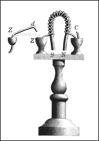
The fix came from an American schoolteacher in Albany, New York, named Joseph Henry, and it is worth dwelling on because it is the single most load-bearing idea in the entire craft of coil-making. Henry insulated the wire rather than the core. He wrapped his copper in silk thread — reportedly cannibalising his wife’s silk petticoats for the purpose — so that the turns could be wound tightly against one another, layer upon layer, hundreds of them, without shorting. That is the whole secret. Every coil wound since, from a Ruhmkorff secondary to a modern switch-mode toroid, depends on insulation on the conductor so that many close turns can share the same small space. The magnet-wire volume is entirely about the descendants of Henry’s silk — enamel films a few micrometres thick that do the same job at a fraction of the bulk.
The results were spectacular for the time. By 1831 Henry had built electromagnets that lifted first hundreds and then well over a ton — one made for Yale hoisted more than 2,000 pounds — from batteries no larger than Sturgeon’s. He also drew a distinction that still matters to anyone winding a coil for a given source: a “quantity” magnet wound with several coils in parallel suited a low-voltage, high-current battery, while an “intensity” magnet wound as one long series coil suited a high-voltage source. That is impedance matching, described decades before the word existed, and it is the same reasoning a designer uses today when choosing turns to suit a supply.
3.4 1831: induction, and the birth of the inductor as an idea
An electromagnet is a coil that makes a magnetic field from a current. The inductor proper is the reverse and more subtle idea: a coil in which a changing magnetic field makes a voltage. That discovery, the true conceptual birth of the inductor, belongs to 1831 and to two men working independently on opposite sides of the Atlantic.
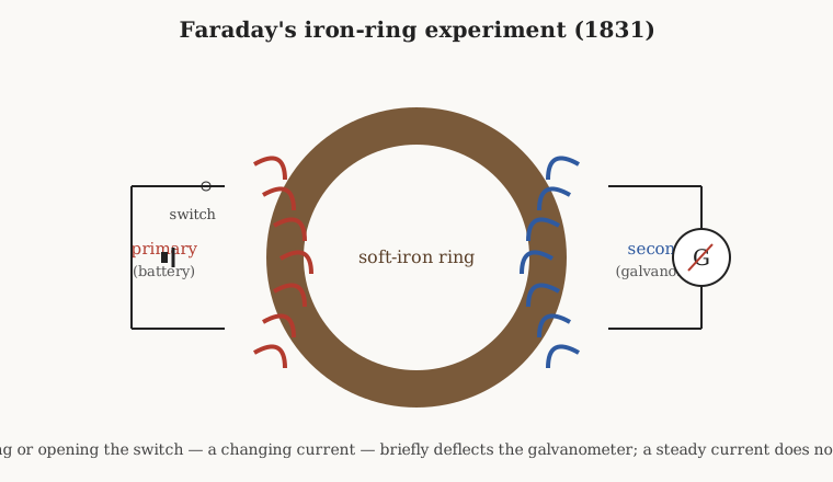
At the Royal Institution in London, Michael Faraday wound two separate coils on opposite sides of a soft-iron ring — a primary connected to a battery through a switch, a secondary connected to a galvanometer. When he closed the switch, the galvanometer needle kicked once and fell back to zero even though the battery was still connected. When he opened the switch, it kicked the other way. A steady current in the primary did nothing at all. Faraday grasped what this meant: it was not the current in the primary that induced anything, but the change in it — the rising or collapsing magnetic flux through the ring. He captured the result in what is now called Faraday’s law: the induced voltage equals the rate of change of magnetic flux linkage. That iron ring is, in effect, the first transformer, and the theory it launched underlies every coil in this series.
Across the ocean, Joseph Henry had seen the same effect at least as early — he had noticed the vicious spark that jumped when he broke the circuit of one of his big electromagnets — but the schoolteacher’s timetable left him little time to write, and Faraday’s paper reached print first. Henry’s lasting priority is elsewhere, and it is central to this volume: he was the first to describe and correctly interpret self-induction. A coil, he realised, induces a voltage not only in a neighbour but in itself. Its own changing current threads its own turns with changing flux, and the coil pushes back against the change — which is exactly why breaking the circuit of a big magnet throws a fat spark, as the coil struggles to keep its current flowing into the suddenly open gap. That push-back is inductance, the property the whole component is named for. When the international electrical community came to name a unit for it, at the Chicago congress of 1893, they called it the henry. It is a fitting memorial: the man who insulated the wire also named the quantity that the wire, wound into turns, so stubbornly defends.
One more name belongs here. In 1834 the Russian physicist Heinrich Lenz gave the effect its sign: the induced current always flows so as to oppose the change that produced it. Lenz’s law is why an inductor behaves like electrical inertia — the flywheel analogy the theory volume dwells on — and why a coil, left to itself, would rather keep its current exactly as it is, thank you.
3.5 The induction coil: chopping DC to make high voltage
The first coil to become a manufactured product, rather than a laboratory curiosity, was the induction coil — and here the record needs correcting, because the popular name gives the credit to the wrong man.
The device was invented in 1836 by the Reverend Nicholas Callan, professor of natural philosophy at Saint Patrick’s College, Maynooth, in Ireland. Callan’s insight was to marry Faraday’s induction to a mechanical interrupter. Wind a primary of a few turns of thick wire and a secondary of very many turns of fine wire on the same iron core. Now chop the primary’s direct current on and off rapidly with a vibrating contact. Each interruption collapses the primary’s flux violently, and because the secondary has so many more turns, the induced voltage in it is enormous — enough to leap a spark gap. Callan drew sparks several inches long, at a time when such voltages were the stuff of thunderstorms, and in doing so he built the first practical step-up transformer, driven not by alternating current (which barely existed yet) but by a chopped direct current.
Callan worked at a theological college where the natural sciences were tolerated rather than celebrated, and his priority was largely forgotten until a Maynooth successor documented it in the 1930s. In the meantime the device acquired the name of the Parisian instrument-maker who perfected and sold it: Heinrich Daniel Ruhmkorff, whose beautifully built coils, patented from 1851, drew sparks a foot or more long and became standard equipment in every serious laboratory. To this day a big induction coil is called a “Ruhmkorff coil,” which is a little unfair to a country priest but very good for the reputation of French workmanship.
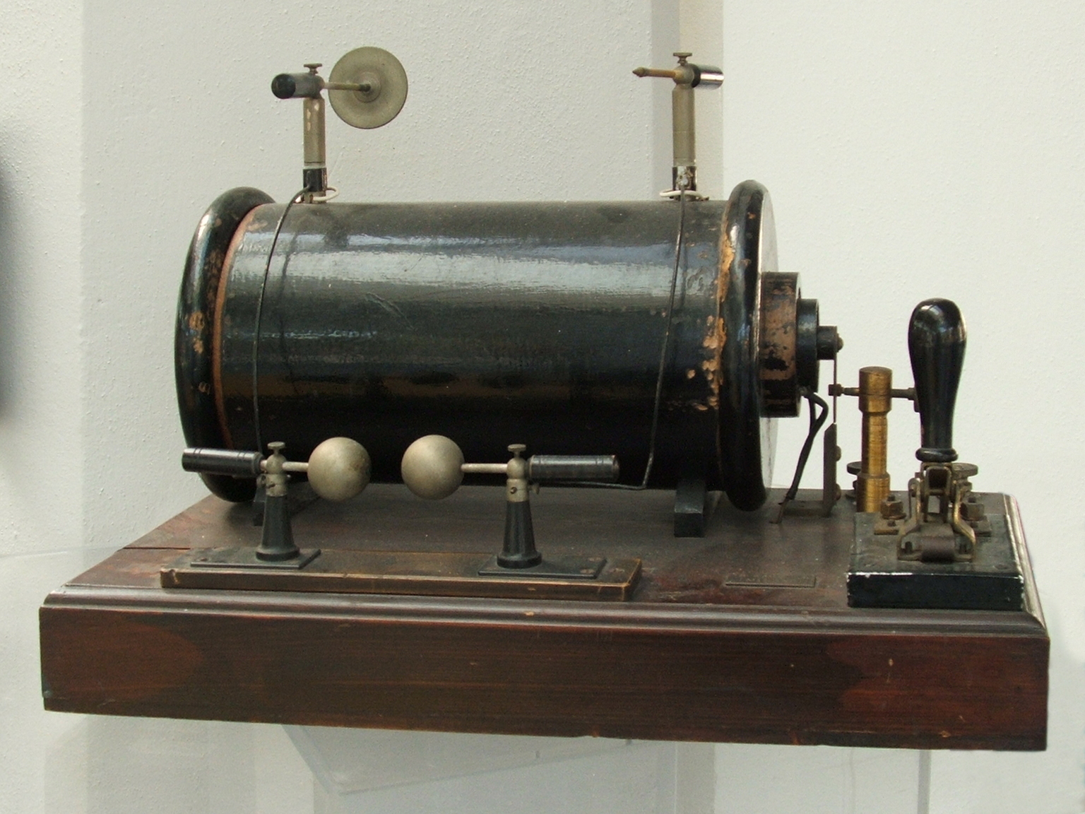
Two refinements turned Callan’s rough sparker into Ruhmkorff’s precision instrument, and both are worth an engineer’s attention. The first was the interrupter itself — a spring-and-hammer contact (often called a Wagner hammer, after the same self-interrupting mechanism used in electric bells) that made and broke the primary automatically, tens or hundreds of times a second. The second, added by Armand Fizeau in 1853, was a capacitor placed across the interrupter contacts. Without it, the break was slow and mushy: the collapsing primary threw a spark across the opening contacts, which held the current up and softened the very change the coil depended on. The capacitor absorbed that surge, let the contacts open cleanly, and sharpened the collapse — squeezing far more voltage out of the secondary. Anyone who has read the capacitors dive will recognise this as the ancestor of the contact-breaker condenser in a car’s ignition, and indeed the induction coil is the direct forebear of both the automobile ignition coil and the true AC transformer that the coming transformers volume takes up.
The induction coil’s influence in the second half of the nineteenth century is hard to overstate. It powered the Geissler and Crookes tubes that lit up physics lectures; it drove the very first X-ray tubes, so that when Wilhelm Röntgen discovered X-rays in 1895 the high voltage behind his tube came from a Ruhmkorff coil; and it excited the spark-gap transmitters of the first wireless telegraphy, so that the opening chapter of radio was written with a coil chopping DC into sparks. For a device conceived by a forgotten Irish priest, the induction coil kept remarkably grand company.
3.6 Tesla and the discovery of resonance
The induction coil made high voltage by brute interruption. The next leap was to make it by resonance, and it is inseparable from the name of Nikola Tesla. Tesla patented his coil circuit on 25 April 1891 and demonstrated it publicly the following month, in a celebrated lecture before the American Institute of Electrical Engineers at Columbia College in New York.
The Tesla coil is an air-core resonant transformer, and its cleverness lies in tuning. A primary circuit — a capacitor charged to high voltage, dumped through a spark gap into a few turns of heavy conductor — rings as an LC oscillator at a high radio frequency. Loosely coupled to it sits a secondary of many hundreds of turns, deliberately built so that its own inductance and self-capacitance resonate at the very same frequency. Energy sloshed from primary to secondary arrives in step, cycle after cycle, and the voltage climbs by the resonant rise of a high-Q circuit until it stands as a corona or a spray of sparks feet long. There is no iron; at these frequencies iron would simply cook itself with losses, a point the core-materials volume returns to. The field is shaped by air and geometry alone.
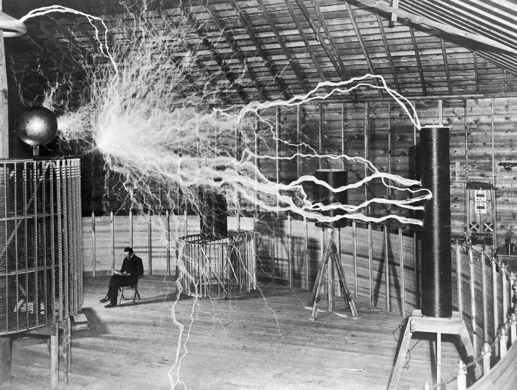
Tesla did not invent electrical resonance out of nothing — Joseph Henry, William Thomson (Lord Kelvin), and Oliver Lodge had all played with the oscillatory discharge of a Leyden jar before him, and Lodge’s “syntonic jars” of 1889 showed two circuits could be tuned to answer each other. But Tesla’s contribution was to make the resonant, air-cored, loosely coupled transformer a deliberate engine for generating very high voltages at very high frequencies, and — more important for what came next — to hammer home the idea that a coil could be tuned to a frequency. That idea, that a coil and a capacitor together pick out one frequency and reject the rest, is the seed of all radio.
3.7 Coils make radio possible
If the nineteenth century discovered the coil, the early twentieth century turned coil-winding into an art form, and the reason was radio. A radio receiver’s central trick is selectivity: out of a sky full of signals it must resonate at one frequency and ignore the neighbours. That job falls to a tuned circuit — an inductor and a capacitor in league — and the theory volume shows why their resonant frequency depends on the product of the two. Turn the variable capacitor (or, as often, adjust the coil) and the station changes. Every crystal set, every regenerative receiver, every superheterodyne that followed has a coil at the heart of its tuning.
The trouble was that a good RF coil is a fussy thing to wind. At radio frequencies an inductor is judged by its Q — the sharpness of its resonance — and Q is spoiled by two enemies the real-inductor volume treats in detail. The first is the coil’s own stray capacitance between turns, which lets signal sneak past the inductance and drags the self-resonant frequency down. The second is proximity effect, in which the magnetic field of each turn crowds the current in its neighbours into a thin skin, raising the effective resistance. A simple close-wound multilayer coil is bad on both counts: adjacent layers run parallel and close, piling up turn-to-turn capacitance and proximity loss.
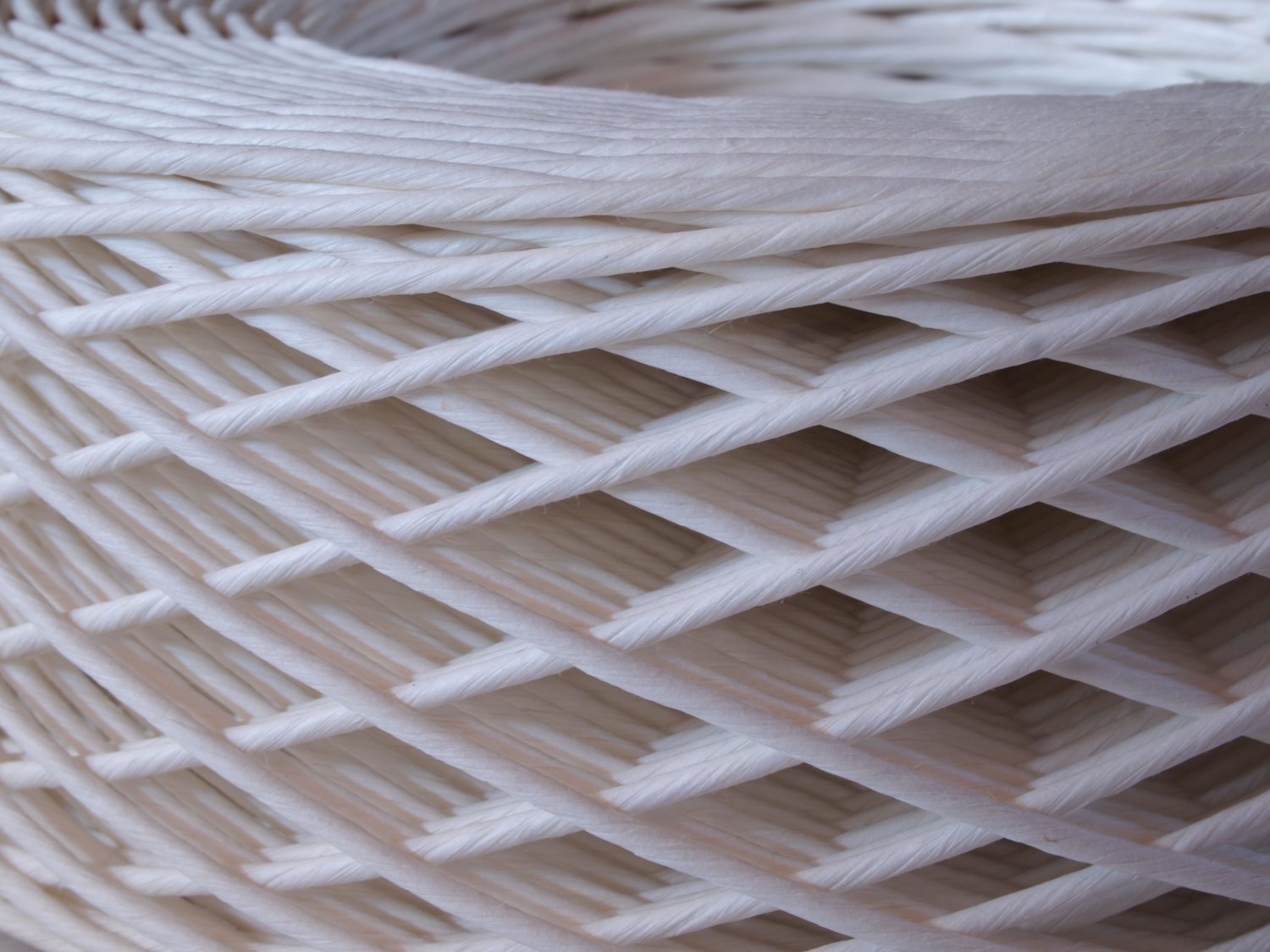
The winders of the 1910s and 1920s answered with some of the most beautiful geometries in the whole component catalogue, all aimed at making successive turns cross at steep angles and sit far apart. In the honeycomb or duolateral coil, the wire is laid in a criss-cross lattice so that each turn crosses the one beneath it at a wide angle, minimising the parallel overlap that breeds capacitance. The basket-weave coil threads the wire in and out of an odd number of pegs or slots, again forcing the crossings toward ninety degrees. The spiderweb coil lays a flat spiral across the spokes of a slotted disc, spacing the turns in a single plane. Bank winding stacks turns in a special progressive order so that physically adjacent turns are far apart electrically, keeping the voltage between neighbours — and hence the stored stray charge — small. The geometries volume dissects all of these; the point here is historical. These were not decorative flourishes. Each pattern is a considered attack on self-capacitance and proximity loss, worked out empirically by winders who could hear the difference in a headphone long before anyone could measure Q on a bridge.
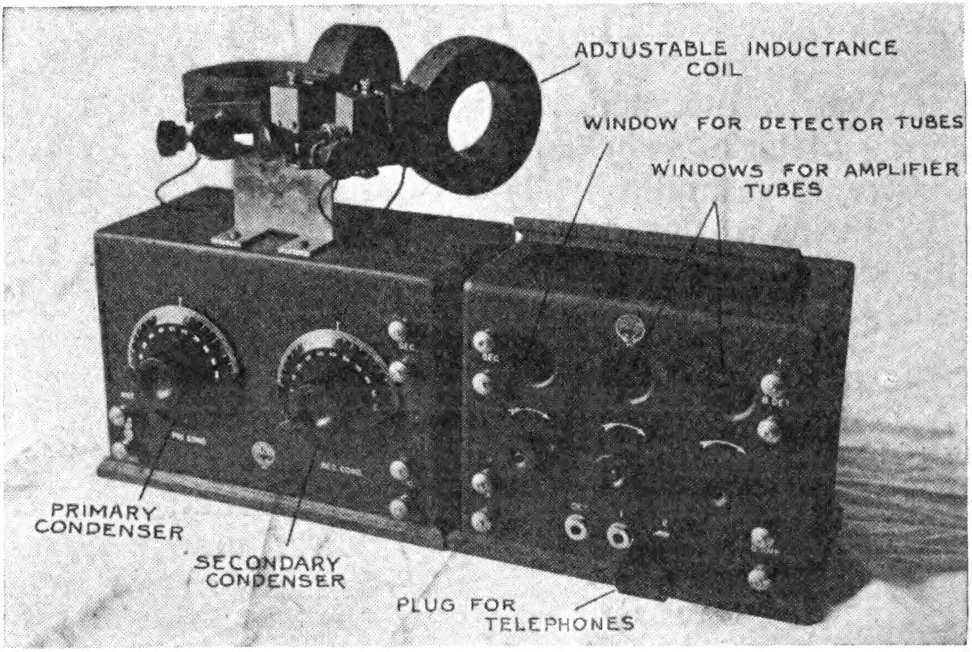
Tuning itself became a coil craft. The variometer — one coil rotating inside another, so that turning the rotor added or subtracted its field from the stator’s and so varied the total inductance — let an operator tune a set by adjusting the coil rather than a capacitor. Its cousin the variocoupler varied the coupling between an antenna coil and a tuned coil. These variable inductors, and the plug-in honeycomb coils sold in graded sets so a listener could swap the tuning range, are the reason a 1920s receiver looks, on the inside, like a nest of exquisitely wound baskets.
3.8 The loading coil: making long-distance telephony work
While radio was learning to wind coils for high Q, the wired network was using coils to solve a very different problem: how to send a voice down hundreds of miles of copper without it dissolving into mud. A long telephone line has resistance and, crucially, capacitance between its conductors; that capacitance progressively shorts out the higher voices, so speech arrives attenuated and smeared. The early trans-continental dream kept running aground on it.
The theory came from the reclusive English genius Oliver Heaviside, who in 1887 worked out what is still called the Heaviside condition: a line transmits without distortion when the ratio of its series resistance to its shunt conductance equals the ratio of its series inductance to its shunt capacitance. Real lines have far too little inductance to satisfy it, so signals of different frequencies travel at different speeds and fade by different amounts. Heaviside’s remedy, proposed in 1893, was to add inductance deliberately — and, since spreading it continuously along the line was impractical, to insert lumped inductors at regular intervals. He never persuaded the British Post Office to try it.
The idea was carried into practice in America around 1899–1900, chiefly by Michael Pupin of Columbia University, with George Campbell arriving at essentially the same result inside AT&T at the same time. A loading coil — a compact, high-inductance coil, later wound on a toroidal core to keep its field contained — is spliced into the line every mile or two (the spacing is dictated by the theory, tighter for higher frequencies). So placed, the coils raise the line’s effective inductance toward Heaviside’s condition, sharply cutting the attenuation and letting a call reach ten times as far on the same copper. The practice became known, after its chief promoter, as pupinization, and the coils as Pupin coils. AT&T, recognising how much money the trick would save on copper alone, paid handsomely to control both Pupin’s and Campbell’s patents. The loading coil is one of those quiet inventions that reshaped the world — the long-distance telephone network was built on it — while remaining utterly invisible to the people whose voices it carried.
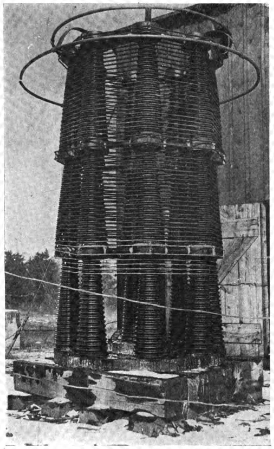
The same principle reappears wherever a conductor is electrically too short or too capacitive for its job. A base-loaded whip antenna — the stubby aerial with a fat coil at its foot — is loaded exactly as Heaviside’s line was, the coil supplying the inductance the short rod cannot. The specialty-coils volume returns to loading coils in that antenna guise.
3.9 The materials revolutions
Through all of this the coil’s core was quietly evolving, and each advance in magnetic material opened a new range of frequencies and powers. The core-materials volume treats the physics; here is the history in brief, because it is the thread that carries the coil from the audio age into the switching age.
For power and audio work, solid iron cores were a disaster: the changing flux drove great eddy currents circulating in the iron itself, wasting energy as heat. The cure, worked out in the closing decades of the nineteenth century and refined with the silicon steels developed after 1900, was to build the core from thin laminations insulated from one another, breaking up the eddy paths. Every mains transformer and audio choke of the twentieth century is built this way — a stack of varnished steel sheets — and the winding on a filter choke in a valve amplifier is a direct industrial descendant of Henry’s insulated coil.
Laminated steel served up to a few kilohertz, but as radio and carrier telephony pushed higher, even thin laminations lost too much. The answer for high-frequency work was the powdered-iron or dust core: fine iron (or, later, permalloy) particles each coated in insulation and pressed into shape, so that the magnetic material is finely divided and the eddy currents are trapped inside grains too small to matter. Bell Telephone’s engineers pressed powdered permalloy — the extraordinarily permeable nickel-iron alloy that Gustav Elmen had developed at the Bell laboratories from 1914 — into the loading coils of the carrier network, and powdered-iron slugs became the tuning cores of countless radio coils, screwed in and out to trim inductance.
The revolution that defined the modern era, though, was the arrival of the soft ferrites — ceramic magnetic materials, oxides of iron with manganese, zinc, or nickel, that combine useful permeability with very high electrical resistance. Because a ferrite barely conducts, eddy currents can scarcely flow in it, and it stays low-loss up into the megahertz where even dust cores flag. The decisive work was done by J. L. Snoek and his colleagues at the Philips research laboratories in the Netherlands in the 1940s, and Philips marketed the result from 1946 under the trade name Ferroxcube. (Earlier investigators — Hilpert in Germany before the First World War, and Kato and Takei in Japan in the 1930s, whose work led to the founding of TDK — had studied ferrites too; Snoek’s achievement was to understand the material well enough to engineer it, including the frequency ceiling still called the Snoek limit.) Soft ferrite is the material that made the high-frequency, low-loss coil cheap and manufacturable, and with it came the whole apparatus of modern electronics: the ferrite-rod aerial, or “loopstick,” that shrank the tuning coil into a portable radio; the IF transformers of every superhet; and, later, the small efficient inductors and transformers that make switch-mode power supplies possible. The humble ferrite bead — a lossy ferrite sleeve slipped over a wire to soak up high-frequency noise — is a coil of a single turn, and it is on nearly every circuit board made today.
3.10 Miniaturisation, and why coils are still wound
The last chapter of the story is one of shrinking. For most of the twentieth century a coil was a hand-wound or, increasingly, a machine-wound affair: turns laid on a bobbin or a toroid by a winding machine of the kind the winding-machines volume is devoted to. Automatic winders counted the turns, traversed the wire evenly across the former, and held it at constant tension, turning the winder’s art into a production process — but it was still, unmistakably, wire around a core.
Then came the drive toward surface mount and integration. The surface-mount chip inductor arrived in two main breeds: the wirewound chip, which is genuinely a tiny coil wound on a ceramic drum and terminated for reflow soldering, and the multilayer chip, in which the “coil” is a spiral of printed conductor buried between screen-printed layers of ferrite or ceramic, with no discrete wire at all. Planar inductors take the idea onto the circuit board itself, etching a flat spiral into the copper of a PCB — no separate component, just a pattern in the trace. And on the silicon of a radio-frequency integrated circuit, designers lay down on-chip spiral inductors, micrometres across, as part of the chip’s own metal layers. The coil, in these forms, has dematerialised into a photolithographic pattern.
And yet — this is the part that keeps a winding machine earning its place on the bench — an enormous share of the world’s inductors are still wound from wire, and for good physical reasons. Power inductors that must carry real current without saturating need a real core and real copper; a printed spiral cannot store the energy or shed the heat. High-Q RF coils, high-current common-mode chokes, transformers of every size, the inductors in a switch-mode supply, the coils in a guitar pickup or a loudspeaker crossover — all of these are wound, many of them on machines whose lineage runs straight back to the hand-cranked winders of the radio age. Integration swallowed the small, low-power coils; it left the demanding ones exactly where they have always been, on a former, turn by counted turn.
3.11 Two centuries, one act
It is worth ending where the craft began. When Joseph Henry wrapped silk-covered copper around a horseshoe of iron in the 1830s, close turn against close turn, he was performing an act that the whole of this volume has been chasing forward through time: laying insulated wire around a core so that the turns work together. Wind a modern toroidal choke for a switching supply and you do precisely the same thing — enamelled magnet wire, descended from Henry’s silk, laid in even turns around a ferrite ring, descended from Snoek’s Ferroxcube, its inductance measured in the henries that carry Henry’s name. The materials have changed beyond recognition; the machines count the turns for you; the finished part may be smaller than a fingernail. But the essential gesture — turns of insulated wire around a core — has not changed in nearly two hundred years, and it is very likely the reason the reader of this volume owns a coil-winding machine at all.
A closing note on vocabulary, since the story has used the words loosely and the trade uses them precisely. An inductor is the component considered as a circuit element, prized for its inductance. A coil is the physical thing, the wound object — every inductor is a coil, but so is the primary of a transformer and the deflection yoke of a picture tube, which are not usually called inductors. A choke is an inductor whose job is specifically to impede alternating current while passing direct current — an RF choke blocks radio frequencies, a filter choke smooths a power supply — the name a nod to how it “chokes off” the AC. And a reactor is the power engineer’s word for a large inductor deliberately inserted into a high-voltage or high-current system, such as a line reactor limiting fault current or a shunt reactor absorbing the charging current of a long transmission line. Four words, one underlying object: turns of insulated wire around a core, doing what Ørsted’s twitching compass first hinted they might.
Comments (0)