Coils and Coil Winding · Volume 8
Winding Technique and Practice
8.1 What good technique actually buys
The previous volume was about the machine — the arbor that spins, the counter that tallies, the traverse that walks the wire along the former, the tensioner that keeps the strand taut. This volume is about the hands and the habits that run that machine well, because a winder is only as good as the person feeding it. The geometries volume said what shape to wind and the design volume said how many turns to put on it; here the concern is narrower and more physical: how to take a target — say, “forty-two turns of 26-gauge on this toroid, evenly spread, leads brought out cleanly” — and turn it into a coil that actually measures like the design, holds together when it is dropped in a parts bin, and comes out the same the next hundred times.
Good winding technique is the pursuit of six things at once, and they pull against one another just enough to make the craft interesting. Hit the turn count exactly, because inductance scales with the square of the turns and a single miscount is a measurable error. Lay the wire at the right pitch, because the spacing between turns sets the self-capacitance and therefore the self-resonant frequency. Keep the tension constant, because slack turns shift and over-tight turns deform formers or snap fine wire. Avoid damaged turns, because a nicked bit of enamel where two wires cross is a shorted turn that quietly wrecks the inductance and the Q. Bring out clean, terminated leads that a solder joint will actually take. And do all of that repeatably, so the coil is a component and not a lucky accident. A first-timer who internalizes just tension and counting will wind a decent coil; the finer craft — interleaving, spacing, taps, impregnation — is what separates a coil that works from one that keeps working.
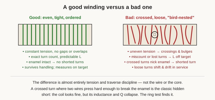
The reader who has never wound a coil should hold one idea above all the others: a coil is a mechanical object that happens to be electrical. Nearly every electrical fault a homemade inductor can have — wrong value, low Q, an outright short — is planted at the moment the wire is laid down, and is invisible afterward. The whole point of technique is to plant no faults.
8.2 Counting turns, and why one miscount matters so much
Start with the count, because it is the parameter most easily botched and the one whose error is most punishing. The inductance of a coil rises with the square of the number of turns; the design volume works this through in detail, but the practical upshot lives here on the bench. On a small coil, going from twenty turns to twenty-one — a five percent miscount — moves the inductance by roughly ten percent, enough to detune a resonant circuit or throw a filter’s corner frequency. Miscount a low-turn RF coil by a single turn and the finished part simply does not meet spec. There is no fixing it after the fact except to unwind and start over, which is why counting is treated as a first-class discipline rather than an afterthought.
The winding machine helps. Its geared or electronic turn counter — the mechanical Veeder-Root register or the optical/Hall pickup described in the machines volume — tallies every revolution of the arbor, and better machines let the winder set a preset that trips an auto-stop exactly at the target count so the motor brakes on the last turn. The counter removes the arithmetic, but it does not remove the two ways the count still goes wrong. First, the machine counts arbor revolutions, and a revolution is only a turn if the wire actually made it once around the former; a slip at the arbor, a skipped engagement, or restarting after a break can put the register out of step with reality. Second, and more insidious, the counter has no idea where the winding began. The disciplined winder therefore marks the start — a dab of paint pen on the former, a note of the counter reading, a photograph — zeroes the register deliberately, and after finishing recounts by eye on anything small enough to count, treating the machine’s number and the eyeball number as two independent measurements that must agree.
For very small coils — a handful of turns of RF wire, a few turns threaded on a bead — the counter is more nuisance than help, and hand-counting wins. Here the toroid presents its own trap, worth stating plainly because beginners get it backward: a turn is counted each time the wire passes through the center of the ring, not each time it wraps the outside. Six passes through the hole is six turns, full stop. The measurement volume closes the loop on all of this: an LCR meter reading that lands well off the designed value, with the wire gauge and core confirmed, almost always means the count is wrong, and the ring or flyback test will separate an honest miscount from a shorted turn masquerading as one.
8.3 Tension: the habit that underlies everything else
If counting is the parameter beginners botch, tension is the technique they never quite appreciate. Tension is the steady pull kept on the wire as it lays down, and it wants to be firm and, above all, constant. Constant matters more than any particular value, because it is changes in tension that produce the visible defects: a moment of slack lets a turn ride up over its neighbor, and a moment of over-pull drags a turn out of line or, on the return, unseats the ones already placed.
The right amount depends entirely on the wire, which is why the wire volume’s gauge and insulation-class information feeds directly into this. Fine magnet wire — 36, 40, 44 gauge, thinner than a hair — will snap under a pull that a coarse wire would shrug off, and its breaking tension is a small fraction of a coarse wire’s, so the tensioner is backed off and the winder learns a genuinely delicate touch. Coarse wire tolerates and wants far more pull, but heavy wire pulled too hard will crush a thin plastic former, bow a bobbin flange, or dig into the layer beneath. Between those extremes the winder is looking for the wire to lie down snug — each turn seating against its neighbor with no visible gap and no bulge — without the strand stretching, because copper drawn past its yield thins slightly, raises its own resistance, and can craze the enamel.
The tension has to survive the transitions, which is where hand-wound coils most often go slack. Starting a winding, taking a tap, and finishing all invite the winder to let the wire go loose while both hands do something else, and every such lapse leaves a soft spot in the coil. Smooth de-reeling helps: the supply spool should pay out without jerking, its own drag light and even, so the tensioner sees a steady feed rather than a series of tugs as the spool’s inertia catches and releases. A winder running fine wire learns to feel the tension through the fingertips — a live, singing tautness that is unmistakable once known, and whose sudden disappearance means the wire has broken somewhere upstream before the eye has even registered it.
8.4 Starting the winding: anchoring the lead
Every winding needs a beginning that will not let go, because the very first turn carries all the tension of the ones that follow and has nothing behind it to hold it in place. The job of the start anchor is to take that strain off the fragile first turn and put it onto something mechanical.
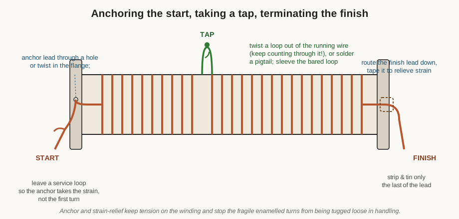
On a bobbin or a flanged former, the classic anchor is a small hole in the flange: the start lead is threaded out through it and given a short service loop — a deliberate bit of slack left outside the winding — so that any pull on the lead lands on the hole and the plastic, never on turn one. Where there is no hole, a couple of turns twisted back on themselves, a tuck under the first few turns so they trap their own tail, or a dab of tape does the same job. On an air-core form with nothing to grab, the start is often a small knot or hitch around the form or through a pair of pin holes; on a toroid, the start lead is simply held under tension by hand until enough turns are down to lock it. Self-bonding wire, discussed later, gives the tidiest anchor of all, because the first turns can be tacked to the form or to each other with a touch of heat.
Whatever the method, the cardinal rule at the start is do not nick the enamel at the anchor. A hole with a sharp edge, a hard twist, or a too-tight tuck can scrape through the thin insulation exactly where the wire is bent hardest, and a bare spot at the start that later touches a bare spot elsewhere is a short. Deburr the hole, keep the bend radius generous, and leave the service loop long enough that the eventual termination is comfortable rather than a fight against a lead that is a centimeter too short.
8.5 Laying the wire: pitch, layers, and neatness
With the start anchored and the tension set, the central craft begins: putting the wire down where it belongs. This is where the traverse mechanism of the machine and the eye of the winder work together, and where the difference between a professional-looking coil and a bird’s nest is decided.
8.5.1 Close-wound versus spaced
The first choice is pitch — the distance from one turn to the next. In a close-wound coil, the pitch equals the wire’s diameter and adjacent turns touch, so the winding is as compact as the wire allows. Close winding packs the most inductance into the least length, is the easiest to lay neatly (each turn seats against its neighbor and self-locates), and is the default for chokes, power inductors, and anything at low frequency where a little turn-to-turn capacitance does no harm.
A spaced or space-wound coil deliberately leaves a gap between turns, so the pitch is larger than the wire diameter. The winder gives up inductance density to buy two things the RF designer prizes: lower self-capacitance, because separated turns store less charge between them, which pushes the self-resonant frequency up; and higher Q, because spreading the turns reduces the proximity-effect losses that crowd the current to one side of each conductor when turns lie tight against one another. The geometries volume explains why a spaced single-layer solenoid is the classic high-Q RF inductor; the technique for making one is the interesting part. The gap has to be held, and there are two honest ways to do it: cut a lead-screw traverse that advances the wire by exactly the chosen pitch per revolution, or space-wind against a thread — lay a second strand of nylon or cotton alongside the wire, wind the two together, then unwind the thread afterward to leave a perfectly regular gap the width of the thread. Trying to hold a spacing by eye alone rarely survives more than a dozen turns.

8.5.2 Layer winding and layer insulation
When one layer of turns will not fit the target count in the available length, the winding climbs into a second layer, and a third, and the coil becomes multilayer. The craft here is to lay each layer as a neat row of side-by-side turns clear across to the far flange, then reverse direction and come back for the next layer on top, and to keep doing it without the turns of an upper layer digging down into the valleys of the layer below. Digging-in is the enemy: a turn that drops into the groove between two lower turns loses its place in the count, shifts the geometry, and can press hard enough to damage enamel. The traditional defense, and the mark of a properly built multilayer coil, is layer insulation — a thin film or tape, often polyester (Mylar) or a similar material, laid over each completed layer before the next is wound. The insulation gives the upper layer a smooth, flat surface to sit on so its turns cannot fall into the layer beneath; it adds turn-to-turn and layer-to-layer voltage withstand; and it simply makes the coil neater and more rugged. Practice is to extend the insulation a millimeter or two past the flanges and to overlap its own edge slightly, so no turn can find a path around the end of the film.
8.5.3 Interleaving, back-winding, and sectioned windings
Layer insulation solves the mechanical problem, but multilayer coils carry an electrical one that the geometries and real-inductor volumes flagged: self-capacitance, and the voltage stress that goes with it. Picture a plain two-layer coil. The first layer runs from turn one at the left flange to turn ten at the right; the second layer returns directly on top, from turn eleven at the right back to turn twenty at the left. Now turn one and turn twenty sit right next to each other — separated by nearly the entire voltage of both layers. That large voltage across a small gap is the single biggest source of a multilayer coil’s distributed capacitance, and the point of greatest insulation stress.
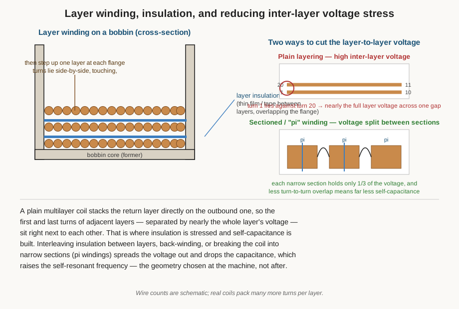
There are three well-worn cures, all decided at the machine rather than after. Interleaving insulation — thicker or more film between layers — simply spaces the offending turns farther apart and raises the withstand. Back-winding (also called the return or bank method) changes the order in which turns are laid so that neighboring turns in adjacent layers differ by only a few turns’ worth of voltage rather than a whole layer’s; it costs some winding complexity and buys a lower capacitance. The most effective, and the reason old RF chokes look the way they do, is sectioning into pi windings: instead of one wide multilayer block, the coil is wound as several narrow ones side by side, each holding only its fraction of the total voltage and coupling weakly to its neighbors. A four-section pi-wound choke sees roughly a quarter of the voltage across any one section and a small fraction of the self-capacitance of the equivalent single block, which is exactly why it self-resonates far higher. The machine’s universal or honeycomb winding, described in the geometries and machines volumes, is the mechanized extreme of the same idea — the traverse crosses the wire back and forth at a steep angle so successive turns cross rather than lie parallel, minimizing the parallel-overlap that builds capacitance.
8.5.4 Filling the window without a bird’s nest
Whatever the scheme, neatness is not vanity; it is electrical. Turns that lie parallel and evenly spaced give a predictable inductance and an intact winding; crossed turns give an uncertain count, unpredictable capacitance, and points where one wire presses across another hard enough to break enamel. The goal on any layer is to fill the window — reach the far flange with the wire arriving exactly at the edge, so the return layer starts clean — and to do it without gaps that let later turns fall in or overlaps that build a hump. When a winding does start to bird’s-nest — pile up in a loose, crossed tangle, usually after a tension lapse — the honest move is to unwind back to the last good turn and re-lay it, because a nest never measures right and never gets better on its own.
8.6 Winding a toroid by hand
The toroid deserves its own section because it is the winding job that defeats the machine most often and falls back onto the fingers. A closed ring has no end to chuck into an arbor; the wire must be passed through the hole once per turn, and general-purpose bench winders cannot do that without a specialized toroid-winding head. So for the hobbyist, and for a great many production parts too, the toroid is wound by hand, and doing it well is a genuine skill.
The job begins before a single turn goes on, with estimating the wire length. Running out of wire three turns from the end of a forty-turn toroid is a special kind of misery, because there is no splicing a magnet-wire coil invisibly and the whole thing must come off. The estimate is straightforward arithmetic: the length of wire per turn is roughly the distance once around the core’s cross-section — over the outside, through the hole, and back — and the total is that per-turn length times the number of turns, plus a generous allowance for the two leads and for the slack the winder inevitably consumes. Core makers publish this per-turn figure, and it is safer to cut a little long and trim than to come up short; the design and reference volumes tabulate typical winding lengths per core size.
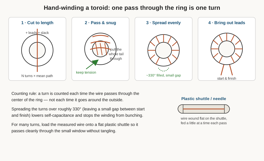
With the wire cut, the method is a rhythm. Anchor the start by holding the lead against the core under tension; pass the free end of the wire through the center of the ring, draw the whole remaining length through, and pull the turn snug against the core — then repeat, each pass adding one turn, each turn seated firmly with steady tension so it does not later flop loose. The winder who has not done it before is always surprised how much wire has to be pulled through the little hole on every single turn; this is precisely why a shuttle earns its keep. A shuttle — a flat plastic or wooden bobbin, or a purpose-made toroid needle — holds the measured length wound flat so that it slips through the window whole, and only a little wire is unspooled from it per pass. For anything past a couple of dozen turns, the shuttle turns a tangled ordeal into a steady, almost meditative process.
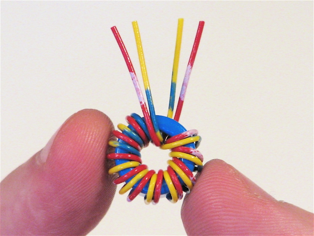
Spreading the turns is the part beginners skip and regret. The turns should be walked evenly around the core’s circumference rather than bunched in one arc, and the received wisdom is to spread a single-layer winding over roughly 330 degrees, leaving a small gap — perhaps thirty degrees — between where the winding starts and where it finishes. Two reasons. First, a gap keeps the start and finish leads (and the large voltage between them) apart, lowering self-capacitance and avoiding a flashover path. Second, evenly spread turns give the inductance the core’s data sheet promises; bunched turns leave part of the core underused and change both the inductance and the way the leakage field escapes. On a multi-turn toroid the winder makes several passes around the ring, each successive pass filling the gaps the previous one left and, on a shuttle, naturally turning in the opposite sense so the layers cross rather than pile.
Counting on a toroid is done by eye — one tally per pass through the hole — and it is worth counting twice, because the recount is the only check there is until the finished part reaches the meter. A toroid that measures low on inductance was almost certainly under-counted or has its turns bunched; one that reads erratically or far off may have a turn whose enamel was scraped passing through the core, which the ring test in the measurement volume will confirm.
8.7 Taps
A tap is a connection brought out from the middle of a winding rather than its ends, and it lets one coil serve as an autotransformer, a multi-band loading coil, or an impedance-matching network. The craft of a good tap is to make the connection without breaking the winding’s tension, its count, or its insulation.
The simplest tap on a continuous winding is a twisted loop: at the chosen turn, the winder pulls a loop of the running wire out from the coil, twists it on itself a few times to make a firm pigtail, and then carries on winding — critically, without losing the count, because the wire never actually stopped, so the turns before and after the tap all still count. The twisted loop’s bared copper is later tinned and becomes the tap terminal. Where a more robust tap is wanted, the winding is paused and a separate pigtail lead soldered to the wire at that point, though this means stripping and soldering enamelled wire mid-coil, with all the care that implies. Either way the bared tap must be insulated — a slip of sleeving or tape over the twist — so it cannot short to the turns it lies against, and it must be given the same strain relief as any other lead so that tugging the tap does not unseat the winding around it.
8.8 Terminating: bringing out and soldering the leads
A coil is only as useful as the connections at its ends, and terminating well is where many otherwise good windings fail. The finish lead is routed out of the winding along a controlled path — down a flange, along the form, out through the toroid’s gap — and given mechanical strain relief, usually a wrap of tape or a tuck under adjacent turns, so that the eventual solder joint and the wire that enters it never take the strain of a pulled lead. A lead that flexes right at the solder joint every time the coil is handled will eventually fatigue and break, invisibly, inside the insulation.
Then comes the enamel. Magnet wire is insulated, and that insulation must be removed or burned through before solder will wet the copper — the single most common cause of a “cold” or failed joint on a homemade coil is solder that appears to flow but has only sat on top of intact enamel, making a mechanical blob with no electrical connection. Some modern solderable enamels are formulated to melt and clear at soldering temperature, so the wire can be tinned directly with a hot iron and fresh solder; the enamel bubbles off and the copper tins in a second or two. Older and heavier insulations — and all the tougher grades such as polyimide — are not self-stripping and must be cleared first, by one of three routes. Abrasion with fine sandpaper, a fiberglass scratch pen, or a knife scrapes the enamel away, and works on any wire, but risks nicking or thinning fine wire and misses the far side unless the wire is rotated. A solder pot — a small crucible of molten solder at a few hundred degrees Celsius — does the job most cleanly for production: the stripped or unstripped end is dipped for a second or two, the heat chars off the insulation, and the copper comes out tinned in one motion, at the cost of fumes, dross, and a dedicated pot. Chemical strippers dissolve certain enamels and suit very fine or bondable wire that abrasion would destroy. The winder chooses by gauge and enamel type: solderable enamel gets the iron, tough enamel gets the pot or the abrasive, hair-fine wire gets the pot or a chemical.
Whatever the stripping method, the soldered joint itself follows ordinary good practice — clean tinned copper, adequate but not excessive heat, fresh flux-cored solder, a joint that is heated so the solder flows into it rather than being dabbed on, and a moment held still while it freezes. A joint that looks dull, grainy, or bulbous is suspect and worth reflowing. Finally the leads are dressed — trimmed to sensible length, routed away from where they can chafe, and, on anything that will see vibration, strain-relieved a second time at the terminal.
8.9 Finishing the coil: tape, varnish, potting, and self-bonding wire
A freshly wound coil, especially a hand-wound one, is often a slightly floppy thing: the turns are held only by their own friction and the tension they were laid with, and they can shift, buzz, or work loose in service. The last stage of technique is to make the winding rigid and permanent, and the difference between a floppy hand-wound coil and a rock-solid production one is entirely in this step.
The lightest measure is simply tape or a tie — a wrap of insulating tape, a dab of adhesive, a few stitches of lacing cord — to hold the outer turns in place. It is quick and reversible and enough for a coil that will live a quiet life. The serious measure is impregnation: dipping or flooding the whole winding with an insulating varnish, resin, or epoxy that wicks into the gaps between the turns and is then baked to cure it into a solid. Impregnation does four jobs at once. It locks the turns mechanically, so nothing shifts and the inductance stays put. It damps microphonics — the tendency of a coil in a magnetic field to sing, vibrating audibly as its turns push on one another, and to act as a microphone in reverse by turning vibration into electrical noise. It excludes moisture, which would otherwise creep into the winding and degrade the insulation. And it raises the voltage withstand by filling the tiny air voids where partial discharge would otherwise start. The plain version is a dip-and-bake: dunk, drain, cure in an oven. The thorough version, for high-voltage or high-reliability coils, is vacuum (pressure) impregnation — the coil is put under vacuum to pull the air out of every crevice, then the varnish is admitted, sometimes under pressure, so it fills the voids the vacuum emptied; the result is a genuinely void-free, monolithic winding. Curing is not optional: an un-baked varnish dries to a much weaker, poorer insulator than a properly heat-cured one.
There is an elegant shortcut for air-core coils that must stand on their own with no former: self-bonding (bondable) magnet wire. This wire carries an extra outer coat of thermoplastic adhesive over its enamel, and once the coil is wound the adhesive is activated — most often by heat (hot air during winding, an oven bake afterward, or simply passing a current through the finished coil to warm it above the bondcoat’s softening point), and in some grades by a solvent such as alcohol applied during winding. The activated coat fuses adjacent turns to one another, and when it sets the coil is a rigid, freestanding, monolithic object with no bobbin or core at all — the standard way voice coils and self-supporting RF coils are made. For the home winder, a heat-set self-bonding air coil is the tidiest possible answer to “how do I make this spaced solenoid hold its shape without a former.”
8.10 Common mistakes, and how to fix them
Nearly every fault in a homemade coil traces back to one of a short list of winding errors, and knowing the list is half of avoiding it. The measurement volume provides the instruments that catch these; the point here is that most are prevented at the machine.
- Miscount. The finished inductance lands well off target with wire and core confirmed correct. Cause: a slipped counter, a lost start reference, or a hand-count error — often a bunched toroid that is really under-turned. Fix: recount by eye against the meter; on a toroid, spread the turns fully before blaming the number.
- Loose or uneven turns. Visible gaps, bulges, and a value that drifts as the coil is handled. Cause: a lapse in tension, especially at a start, tap, or finish. Fix: rewind the loose section under steady tension; anchor and strain-relieve every lead.
- Crossed turns / bird-nesting. A loose, tangled pile, an uncertain count, and erratic capacitance. Cause: tension collapse or an inattentive traverse. Fix: unwind to the last good turn and re-lay; do not try to smooth a nest in place.
- Nicked enamel and shorted turns. The classic hidden failure — the coil looks perfect but its inductance and Q are quietly wrecked. Cause: a sharp anchor hole, a hard crossing, or scraping the wire through a toroid. Fix: there is no fix but rewinding; prevent it by deburring, generous bends, and gentle handling. Confirm with the ring/flyback test.
- Over-tension. Broken fine wire, a stretched strand of raised resistance, or a crushed former. Cause: too heavy a tensioner for the gauge. Fix: back off the tension to suit the wire; let fine wire lie snug, not stretched.
- Wrong pitch. The inductance is off even though the count is right, or the Q and self-resonance are disappointing. Cause: close-winding what should have been spaced, or a spacing that wandered. Fix: hold the pitch with a lead-screw or a spacing thread rather than by eye.
- Messy or shorting taps. A tap that shorts to its neighbors or throws off the count. Cause: an un-insulated twist or a tap taken without keeping the running count. Fix: sleeve every tap and keep the count continuous through it.
- Cold enamel joints. A lead that reads open or intermittent though the solder looks present. Cause: solder sitting on unstripped enamel. Fix: strip or burn the enamel properly — iron on solderable wire, pot or abrasive on tough grades — and reflow into clean, tinned copper.
- Forgotten layer insulation. Upper-layer turns dig into the layer below, the count and geometry drift, and the voltage withstand is marginal. Cause: skipping the interleaving film to save time. Fix: insulate between layers; on high-voltage coils, interleave or section.
8.11 On this bench
The general craft above is deliberately machine-agnostic — it applies whether the wire is being laid by a hand-crank winder, a motorized bench machine, or a programmable one. The winder at this bench runs coils on their own winding machines (detailed in the machines volume), and the practical texture of this setup — which coils get space-wound against a thread, how the toroid shuttles are loaded, what varnish sits on the shelf, the feel of the tensioner at each gauge — is bench knowledge to be shown rather than described secondhand.
With the wire laid, counted, tapped, terminated, and made rigid, the coil is finally a component. What remains is to prove it. The design volume set the target it was wound to hit; the measurement volume takes the finished part to the LCR meter to confirm the inductance, the Q, and the DC resistance, hunts for the self-resonant frequency, and runs the ring test that exposes the one fault this whole discipline exists to prevent — the shorted turn that no amount of looking will reveal. And the build-your-own volume puts all of this to work on real projects wound on the actual machines: an RF coil, a toroidal choke, a common-mode choke, a tapped coil, each a chance to make the technique in these pages muscle memory.
Comments (0)