Coils and Coil Winding · Volume 4
Core Materials and Magnetics
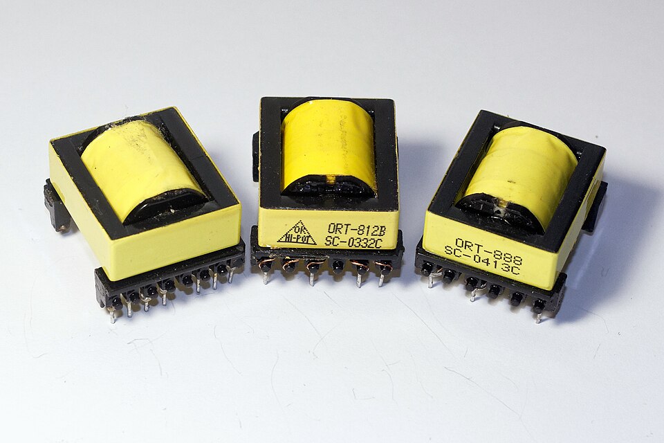
4.1 Why a coil bothers with a core at all
An air-cored coil is an honest thing. Wind some wire into a helix and it stores energy in the magnetic field that threads it; the inductance depends only on the geometry — the number of turns, the diameter, the length — and on nothing that changes with temperature, current, or the phase of the moon. It never saturates, it has no core loss, and its inductance is as linear as a ruler. If that were the whole story, this volume would be a page long.
The trouble is that air is a feeble magnetic medium. To get a useful inductance out of empty space, a coil needs a great many turns and a great deal of room, and every one of those turns adds copper resistance and self-capacitance. The engineer who needs a 10 mH choke that fits on a fingertip, or a switch-mode inductor that stores real joules without melting, cannot get there with air.
A core is the fix. Slide a lump of magnetic material inside the winding and it does two things at once. First, it multiplies the flux: a material of relative permeability µr concentrates the field so that the same current produces µr times as much flux density, and inductance scales with it. A modest ferrite with µr of 2000 turns a coil that would have needed two thousand turns into one that needs a few dozen. Second, it channels the flux, guiding it around a closed magnetic path instead of letting it sprawl into the surrounding air, which cuts leakage and lets nearby components ignore each other.
Nothing in engineering is free, and the core charges for its services. It introduces loss — energy burned as heat every cycle. It introduces saturation — a hard ceiling beyond which the material simply refuses to carry more flux and the inductance collapses. And it introduces temperature dependence — permeability, loss, and that saturation ceiling all drift with heat, and every magnetic material has a temperature above which it stops being magnetic at all. Choosing a core is therefore not a matter of grabbing the highest permeability on the shelf. It is a negotiation among permeability, saturation flux density, loss as a function of frequency, temperature stability, size, and cost — and the right answer is different for a 50 Hz mains choke, a 200 kHz buck converter, and a 30 MHz antenna trap. This volume is where that negotiation happens.
The saturation and core-loss mechanisms sketched in the real-inductor volume are unpacked here in full; the AL values and gapping arithmetic introduced below are carried to worked numbers in the design volume; and the shapes surveyed at the end set up the bobbins and formers of the winding volumes.
4.2 The magnetic quantities, made precise
Magnetics has a reputation for being the murky corner of electrical engineering, mostly because the quantities have unfamiliar names and the units come in two competing systems. It is worth pinning them down, because the whole of core selection is bookkeeping in these terms.
Start with cause. A current I flowing through N turns produces a magnetomotive force (MMF) equal to the product N·I, measured in ampere-turns. MMF is the magnetic analogue of voltage — the thing that drives flux around a magnetic circuit. Ten turns carrying one amp and one turn carrying ten amps produce the same ten ampere-turns and, other things equal, the same magnetic effect.
Spread that MMF along the length of the magnetic path and you get the field strength H, measured in ampere-turns per metre. H is the effort applied to the material — how hard the coil is pushing — and it depends only on the current and the winding, not on what the core is made of. For a toroid of magnetic path length l, simply H = N·I / l.
The material’s response to that effort is the flux density B, measured in tesla (T) in SI, or in gauss in the older CGS system that core datasheets stubbornly still use (1 T = 10,000 gauss). B is how much magnetic flux is packed through each square metre of core cross-section. The ratio of response to effort is the permeability:
µ = B / H
Permeability is usually quoted relative to the permeability of free space, µ0 = 4π × 10⁻⁷ henries per metre, as the dimensionless relative permeability µr = µ / µ0. Air, and every non-magnetic material, has µr = 1. A power ferrite has µr around 2000; a high-permeability nanocrystalline alloy can exceed 100,000. That single number is the multiplier the core applies to the coil’s inductance.
Two more ideas complete the picture. Reluctance is the magnetic circuit’s resistance to flux — its “magnetic ohms” — given by ℛ = l / (µ·A) for a path of length l and cross-section A. A short, fat, high-permeability path has low reluctance and carries flux easily; a long, thin, or low-permeability path resists it. This yields a tidy analogy to Ohm’s law, which is the most useful mental model in the whole subject:
Table 1 — Two more ideas complete the picture. Reluctance is the magnetic circuit's resistance to flux — its "magnetic ohms" — given by ℛ = l / (µ·A) for a path of length l and cross-section A. A short, fat, high-permeability path has low reluctance and carries flux easily; a long, thin, or low-permeability path resists it. This yields a tidy analogy to Ohm's law, which is the most useful mental model in the whole subject
| Electrical circuit | Magnetic circuit |
|---|---|
| Voltage V (volts) | MMF F = N·I (ampere-turns) |
| Current I (amps) | Flux Φ (webers) |
| Resistance R = ρl/A | Reluctance ℛ = l/(µA) |
| V = I·R | F = Φ·ℛ |
Reluctances in series add, gaps and cores combine like resistors, and the whole magnetic path can be reasoned about the way a first-year student reasons about a resistor network. This is exactly how an air gap gets analysed later: it is simply a large reluctance in series with the core’s small one.
The one place the analogy breaks — and it breaks hard — is that resistance is roughly constant while permeability is emphatically not. Push H high enough and every magnetic material runs out of magnetic domains to align. Beyond that point B barely rises no matter how much more current is forced through; the material has reached its saturation flux density, Bsat. Above saturation the incremental permeability falls toward that of air, the inductance collapses, and a switch-mode inductor that saturates dumps its current into whatever transistor is unlucky enough to be switched on. Bsat is the single hardest ceiling in core selection, and it is the first number an engineer looks up. It ranges from about 0.25 T for a low-permeability nickel-zinc ferrite to roughly 2 T for grain-oriented silicon steel — nearly an order of magnitude, and the reason the two materials never compete for the same job.
4.3 Hysteresis: the B–H loop
If a core were a perfect spring, B would trace H up and back down the same line and the energy put in on the rising half would be recovered on the falling half. Real ferromagnetic materials are not springs; they have memory. Drive H up and back down and B traces a fatter path down than it did up, because the magnetic domains that were levered into alignment do not all snap back when the field is removed. The closed curve this traces is the hysteresis loop, and it is the signature of a magnetic material.
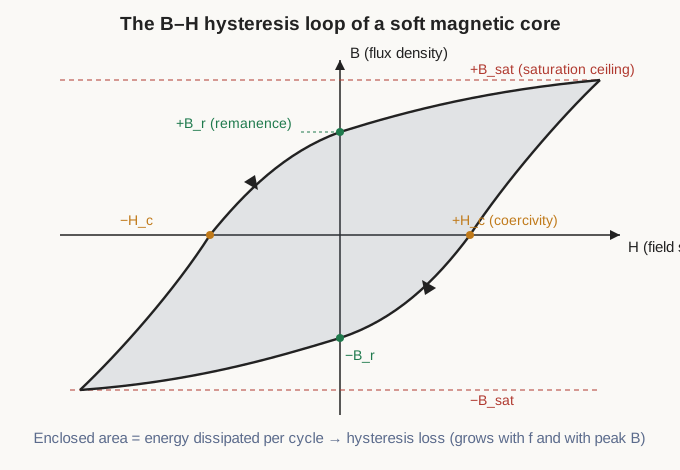
Three features of the loop earn names. Where the flat tops flatten off is saturation, Bsat, already met. Where the loop crosses the vertical axis — the flux that remains when the drive current returns to zero — is the remanence or retentivity, Br; it is the core’s leftover magnetism. Where the loop crosses the horizontal axis — the reverse field needed to knock B back to zero — is the coercivity, Hc; it measures how stubbornly the material clings to its magnetisation.
The area enclosed by the loop is the payload. It has the units of energy per unit volume, and it is precisely the energy dissipated as heat in the material on each trip around the loop. Traverse the loop f times a second and the hysteresis loss is that area times f — loss that climbs in direct proportion to frequency and, because a bigger flux swing fattens the loop, climbs faster still with peak flux density (empirically closer to the square of Bpeak). This is one of the two great core-loss mechanisms, and it is why a material’s loop wants to be as thin as possible for a core and as fat as possible for a permanent magnet.
That distinction is the difference between soft and hard magnetic materials. A soft material has a slim loop — low coercivity, low remanence, low hysteresis loss — and magnetises and demagnetises easily; these are the core materials, the whole subject of this volume. A hard material has a broad loop with high coercivity and high remanence, resists being demagnetised, and makes a good permanent magnet — the opposite of what a core wants. Everything from here on is a study of how to make the softest, most obliging loop for a given frequency and flux level.
4.4 Eddy currents, and the two ways to beat them
Hysteresis is only half of the core loss. The other half is subtler and, at high frequency, far more punishing.
A changing magnetic field induces a voltage in any conductor it threads — that is Faraday’s law, the same law that makes the inductor work. A solid metal core is a conductor, so the changing flux inside it induces little circulating currents, swirling in loops perpendicular to the field like eddies in a stream. These eddy currents flow through the resistance of the core metal and dissipate energy as heat, contributing nothing useful. Worse, they generate their own opposing flux that shoves the main flux out toward the surface of the core, so the interior stops carrying its share. Eddy loss rises with the square of frequency and the square of flux density, which is why a solid iron core that behaves impeccably at 50 Hz turns into a heater at 50 kHz.
There are exactly two ways to strangle eddy currents, and they define the two great branches of core materials.
The first is to laminate the core: build it from thin sheets of the metal, each coated with an insulating varnish or oxide, stacked so the insulation lies across the eddy-current paths. The circulating currents are confined to each thin sheet, their loops are tiny, and the loss drops with roughly the square of the sheet thickness. Mains and audio transformers are built this way, from silicon-steel laminations typically 0.35 mm thick, thinned toward 0.1–0.2 mm for higher-frequency grades. Adding silicon to the iron also raises its electrical resistivity, throttling the eddy currents further — which is why “electrical steel” is a silicon-iron alloy rather than plain iron.
The second is to abandon bulk metal altogether and use a material that is a poor conductor to begin with. Ferrites are ceramics — sintered oxides of iron with manganese-zinc or nickel-zinc — with electrical resistivity millions of times that of iron. Eddy currents can barely flow in a material that scarcely conducts, so ferrites carry flux to megahertz and beyond with negligible eddy loss. The related trick is to grind a magnetic metal into a fine powder, coat each particle with insulation, and press the coated grains into a core; the insulation between grains blocks the eddy currents while the grains still carry the flux. This is the basis of powdered-iron and the various powder cores (sendust, MPP, and their kin). Powder cores carry a bonus that turns out to be central to power design: the insulation between grains acts as a microscopic distributed air gap, a point returned to below.
So the map of core materials is really a map of eddy-current strategies against frequency: laminated steel for line and audio frequencies, ferrite and insulated powder for everything above.
4.5 The material families
This is the meat of core selection. Each family occupies a band of frequency and a range of saturation flux density, and knowing where each one wins is most of the engineering. The families are surveyed below and then gathered into a single comparison table.
4.5.1 Air and non-magnetic formers
The baseline, and not a consolation prize. A coil wound on a plastic, ceramic, or phenolic former — or on nothing at all — has µr = 1, no core loss, and no saturation of any kind. Its inductance is perfectly linear with current and rock-stable with temperature, drifting only as the former expands. What it lacks is inductance density: with no permeability multiplier, a useful value needs many turns and physical size.
That trade is worth making wherever linearity and loss matter more than size. Air-cored coils dominate high-power RF (transmitter tank circuits and antenna matching networks, where a ferrite would saturate or cook), high-linearity filters that must not generate harmonics, and any application above roughly 100 MHz where even the best core material is more trouble than help. When an RF engineer winds a self-supporting coil of silver-plated tubing, that is an air core chosen on purpose.
4.5.2 Silicon steel and laminations
At the opposite extreme sits the workhorse of the power grid. Silicon steel — iron alloyed with about 3% silicon, rolled into thin laminations — combines a high permeability (initial µr from a few thousand to, for grain-oriented grades, tens of thousands) with the highest saturation flux density of any common core material, roughly 1.9 to 2.0 tesla. That enormous Bsat is why the mains transformer in every appliance, and the giant on the utility pole, is built from it: high Bsat means a lot of flux through a modest core cross-section, and a lot of volts per turn.
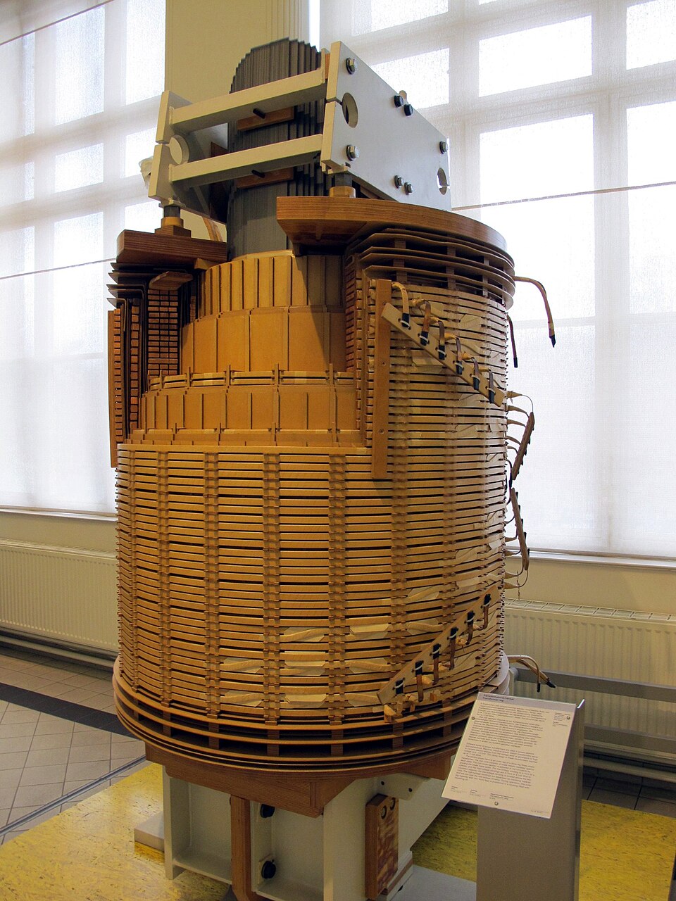
The catch is frequency. Even laminated and silicon-loaded, the metal’s eddy-current and hysteresis losses climb steeply, and silicon steel is confined to line frequency (50/60 Hz), aircraft power (400 Hz), and audio. Push it into the kilohertz and the laminations must grow absurdly thin and the loss still wins. This is fundamentally a low-frequency, high-flux material — the domain of the coming transformers volume, and of filter chokes on rectified mains — and it does that job better than anything else. Its Curie temperature, above which it ceases to be magnetic, is a comfortable ~745 °C, so heat is never the limiting factor; loss is.
4.5.3 Soft ferrites: MnZn versus NiZn
Ferrites are the material that made switch-mode power and modern RF practical, and they come in two families that between them cover an astonishing span of frequency.
Manganese-zinc (MnZn) ferrite is the higher-permeability, lower-resistivity branch. Initial permeabilities run from around 1000 to well over 10,000, with power grades clustered around 2000–2300, and saturation flux density sits near 0.4–0.5 T at room temperature (Fair-Rite’s material 77, a representative power grade, quotes an initial µ of about 2000 and Bsat around 0.51 T, falling toward 0.4 T as the core heats). Its resistivity, though vastly higher than metal, is the lowest among ferrites, so eddy losses eventually catch up; MnZn is the material of choice from a few kilohertz up to roughly 1–3 MHz — exactly the band of switch-mode power conversion and low-frequency EMI suppression. The transformer and output choke of nearly every off-line power supply are wound on MnZn ferrite.
Nickel-zinc (NiZn) ferrite is the lower-permeability, far higher-resistivity branch. Initial permeabilities run from single digits up to around 800 (Fair-Rite’s material 43 is µ ≈ 800, material 61 is µ ≈ 125, and the very-high-frequency mixes drop to µ ≈ 15–40), with Bsat lower than MnZn, around 0.25–0.35 T. The prize is resistivity orders of magnitude higher again, which pushes eddy loss out of the way and lets NiZn work from a few megahertz to hundreds of megahertz. This is the material of RF chokes, wideband transformers, baluns, and the ubiquitous ferrite bead and clamp-on suppressor. The rule of thumb is blunt and useful: MnZn for power and lower frequency, NiZn for RF and higher frequency.
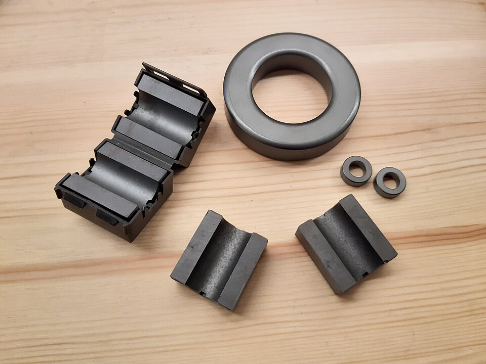
The reason the two families divide the spectrum so cleanly is that a ferrite’s permeability holds flat only up to a knee frequency, above which it falls and the loss climbs. The higher the permeability, the lower that knee — so the high-µ MnZn runs out of road first, and the low-µ NiZn carries on to much higher frequencies. Powdered iron, with lower µ still, extends the trend further.
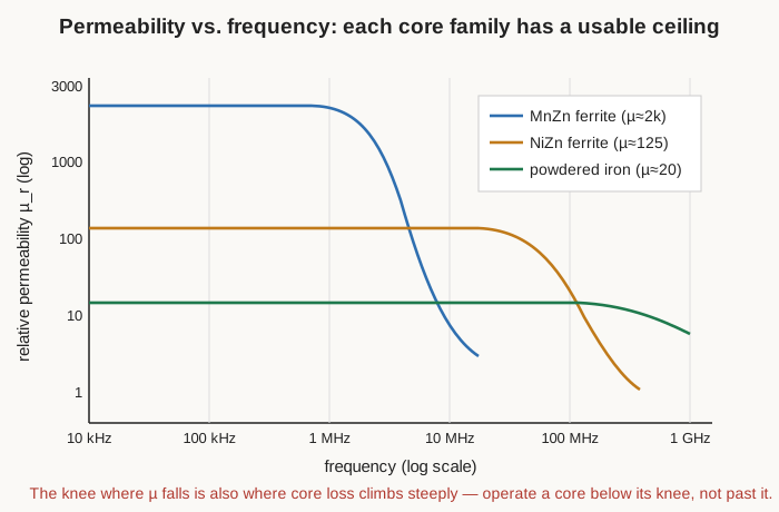
Two cautions come with ferrites. Their saturation flux density, already modest, falls with temperature — a MnZn core good for 0.5 T at 25 °C may manage only 0.35 T at 100 °C, and a design must budget for the hot value. And their Curie temperature is low, typically 200–250 °C for power MnZn grades (higher for low-µ NiZn), above which the material abruptly loses its magnetism; a ferrite driven into thermal runaway can cross its Curie point and take the circuit with it.
4.5.4 Powdered iron
Powdered iron is what you get when the eddy-current fix — insulated grains — is applied to plain iron. Fine iron powder (often carbonyl iron, produced as microscopic spheres) is coated and pressed into cores, most familiarly the coloured toroids stocked by Amidon and made by Micrometals, whose colour codes name the mix: material #2 (µ ≈ 10), #6 (µ ≈ 8.5), #26 (µ ≈ 75) and the rest, each painted a standard colour so it can be identified from the parts bin.
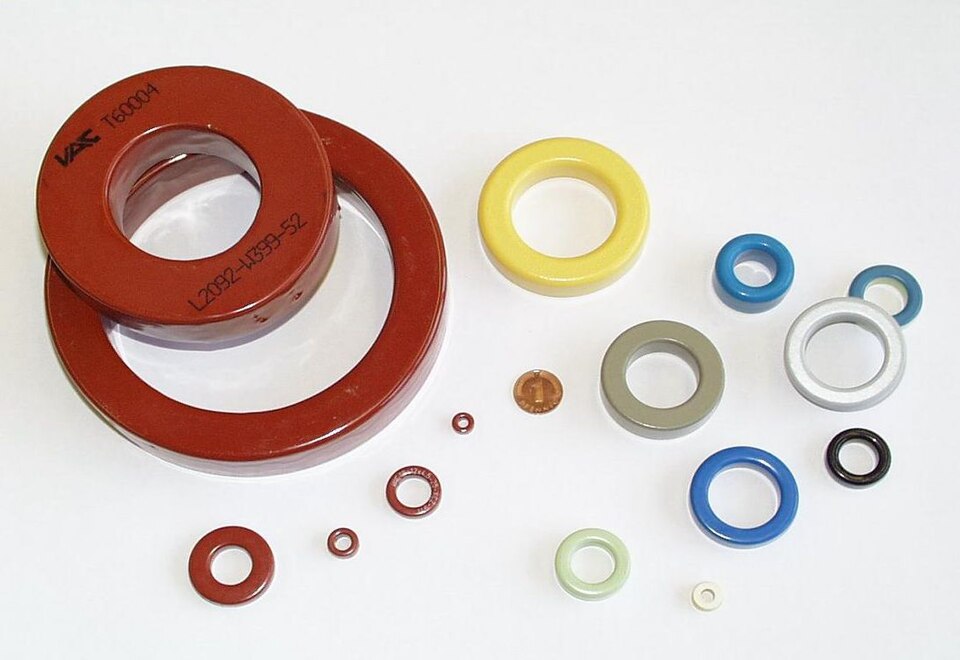
The permeability is low — from single digits to about 100 — because the insulation between grains behaves as a distributed air gap woven through the whole volume. That same distributed gap gives powdered iron its two great virtues: a high saturation flux density (roughly 1.0–1.5 T, far above ferrite) and a soft, gradual saturation — the core loses inductance slowly and predictably as current rises rather than cliff-diving the way an ungapped ferrite does. The carbonyl-iron mixes also hold their low permeability remarkably steady with frequency and temperature, which makes them excellent for RF: tuned circuits, traps, and RF chokes where a stable, low-loss, low-µ core is wanted.
The price is core loss. Powdered iron is lossier than ferrite at a given frequency and flux, so it suits high-current power chokes where the flux swing is small (the DC-bias case) and low-loss-not-critical filtering, but not the large-swing, high-frequency transformer duty that belongs to ferrite. Some iron-powder mixes also suffer irreversible thermal ageing if run too hot for too long — a real derating in continuous power service.
4.5.5 Sendust, MPP, High Flux, and the tape-wound alloys
Between plain iron powder and ferrite sits a family of engineered powder cores that keep the distributed gap and soft saturation of iron powder while cutting the loss and adding DC-bias performance ferrite cannot touch. They are the quiet stars of modern power design, especially in power-factor-correction chokes and switch-mode output inductors, where a core must hold its inductance under heavy DC bias without a discrete gap.
Sendust, sold by Magnetics Inc. as Kool Mµ, is an iron-silicon-aluminium alloy powder (about 85% Fe, 9% Si, 6% Al). It offers permeabilities of roughly 26–125, a saturation flux density near 1.0 T (about 10,500 gauss), substantially lower loss and better thermal behaviour than plain iron powder, and — critically — a modest price, because it contains no nickel. For many buck and boost inductors it is the default.
Molypermalloy powder (MPP) is a nickel-iron-molybdenum alloy (about 79% Ni, 17% Fe, 4% Mo) with permeabilities from 14 up to 550, the lowest core loss and the best temperature stability of any powder core, and a saturation flux density around 0.75 T (7500 gauss). It is the premium choice where loss and stability rule and cost is secondary — filter chokes and resonant inductors in demanding supplies. Its nickel content makes it expensive.
High Flux is a 50% nickel, 50% iron powder with permeabilities of 14–160 and by far the highest saturation flux density of the powder family, about 1.5 T (15,000 gauss). That high Bsat gives it the best DC-bias performance of the group — the least inductance droop under heavy current — so it wins wherever a choke must survive large DC or peak current in a compact core. Its loss sits between MPP and sendust. A lower-cost silicon-iron variant, XFlux (a 6.5%-silicon iron powder), pushes DC-bias performance higher still at the expense of loss and available permeabilities, and undercuts High Flux on price.
At the top of the frequency-times-flux envelope are the tape-wound alloys: strip of a magnetic metal, only microns thick, wound into a core so that the thinness itself controls eddy loss. Amorphous metals (Metglas and kin), rapidly quenched so the atoms never crystallise, reach Bsat around 1.5–1.6 T for the iron-based grades (and very high permeability at lower Bsat for the cobalt-based ones). Nanocrystalline alloys (FINEMET, VITROPERM) go further: saturation around 1.2–1.3 T, initial permeabilities that can exceed 100,000, very low loss, and a high Curie point near 570 °C. They make superb common-mode chokes and high-frequency power transformers — spectacular performance at a spectacular price, which keeps them out of cost-driven designs.
4.5.6 The comparison table
The families gathered, with representative numbers. Permeability and Bsat vary by grade within each family; the ranges below are illustrative, drawn from manufacturer literature, and any real design must confirm against the specific datasheet.
Table 2 — The comparison table
| Family | Rel. permeability µr | Bsat (approx.) | Useful frequency | Core loss | Where it wins |
|---|---|---|---|---|---|
| Air / non-magnetic | 1 | none (never saturates) | DC to > GHz | none | High-power RF, high-linearity, > 100 MHz |
| Silicon steel (laminated) | ~2,000–40,000 | ~1.9–2.0 T | 50 Hz – audio | high above audio | Mains & audio transformers, line chokes |
| Amorphous (Fe-based) | ~10,000+ | ~1.5–1.6 T | line – tens of kHz | low | High-efficiency power transformers |
| Nanocrystalline | up to > 100,000 | ~1.2–1.3 T | kHz – hundreds of kHz | very low | CM chokes, HF power transformers |
| MnZn ferrite | ~1,000–15,000 | ~0.4–0.5 T | kHz – ~1–3 MHz | low (in band) | SMPS transformers/chokes, LF EMI |
| NiZn ferrite | ~15–800 | ~0.25–0.35 T | ~1 MHz – hundreds of MHz | low (in band) | RF chokes, beads, wideband RF |
| Powdered iron | ~3–100 | ~1.0–1.5 T | LF – VHF (RF grades) | moderate–high | RF tuned circuits/traps, DC-bias chokes |
| Sendust / Kool Mµ | ~26–125 | ~1.0 T | LF – ~1 MHz | moderate | Cost-effective SMPS/PFC chokes |
| MPP | ~14–550 | ~0.75 T | LF – ~1 MHz | lowest (powders) | Low-loss, stable filter/resonant chokes |
| High Flux / XFlux | ~14–160 | ~1.5–1.6 T | LF – ~1 MHz | moderate | Heavy DC-bias chokes, PFC |
4.6 The air gap: trading permeability for headroom
The single most important move in energy-storage inductor design looks, at first glance, like sabotage: deliberately cutting a small gap in an otherwise closed high-permeability core. Why weaken a core on purpose?
Because a high-permeability core, left ungapped, is a poor place to store energy. Its steep, narrow B–H loop means a little current drives it hard toward saturation, and its energy is stored partly in the material where hysteresis burns it. Introduce a gap — a millimetre of air in the magnetic path — and the reluctance of that gap, being air with µr = 1, dwarfs the reluctance of the whole ferrite path around it. The gap now dominates the magnetic circuit. Using the Ohm’s-law analogy, it is a large series resistance that swamps a small one, and it takes control of the coil’s behaviour.
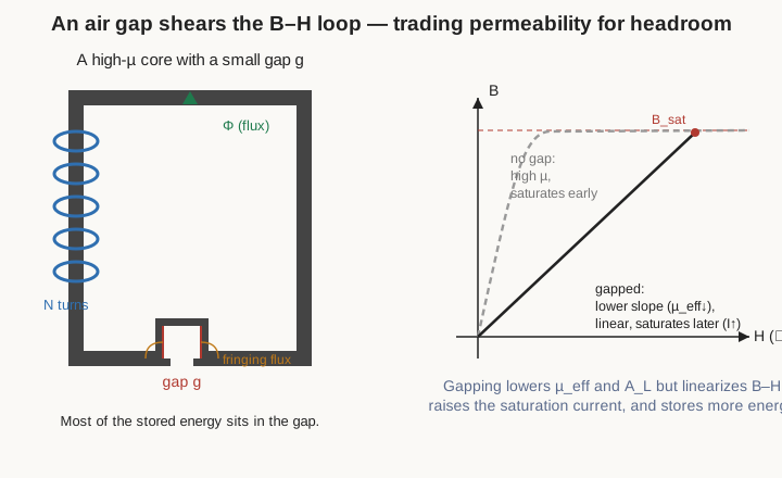
The consequences all flow from that. The effective permeability drops — a core of intrinsic µr 2000 with a modest gap might present an effective µr of only a few hundred — so the inductance drops with it, and more turns are needed for a given value. In exchange, the B–H loop is sheared over: its slope falls but it straightens out and extends much further along the H axis before saturating, so the core tolerates far more ampere-turns — far more current — before it runs out of flux. The behaviour becomes linear, largely set by the geometry of the gap rather than the temperamental permeability of the ferrite, so inductance grows stable against temperature and drive level. And most of the coil’s energy is now stored in the gap — in air, which has no hysteresis and no loss — rather than in the material.
That is exactly the bargain a switch-mode energy-storage inductor wants: linear, stable, and hard to saturate, at the cost of some permeability and some extra turns. It is why the E-core in a flyback or buck converter has a ground-down centre leg, and why the powder cores of the previous section — with their distributed gap already baked into the material — need no discrete gap at all, and behave as a gapped core does but without the fringing losses of a single big gap. The gap does have one nuisance: near its edges the flux bulges outward as fringing flux, which can cut into nearby windings and cause extra loss, so the winding is kept back from the gap.
Two practical notes close the topic. Fringing means a distributed gap (powder) is often gentler than one big lumped gap for the same effective permeability. And the whole business is captured for the designer by a single catalogue number, the AL value — the inductance per turn squared for a given core-plus-gap, quoted in nanohenries per turn² — so that inductance becomes simply L = AL·N² and the turns for a target L fall straight out. The AL value already folds in the core’s permeability, its dimensions, and its gap; the arithmetic of choosing turns, checking the flux swing against Bsat, and sizing the gap is carried in full in the design volume.
4.7 Core shapes, and what each is for
A core’s material sets its magnetic behaviour; its shape sets how it is wound, how well it contains its field, and what it costs. The common shapes are worth knowing on sight.
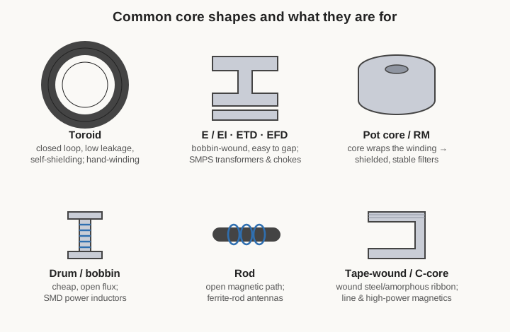
The toroid — a simple ring — is magnetically the best of all. Its path is closed with no gap and no ends, so leakage flux is very low and the core is largely self-shielding; a toroid radiates and picks up far less than an open shape. Its drawback is entirely mechanical: every turn must be threaded through the hole, so a toroid is slow to wind by hand and awkward to machine-wind — the subject of a whole later technique volume on winding toroids with a shuttle. Toroids dominate where field containment matters: EMI filters, common-mode chokes, and RF inductors.
The E-core, and its relatives EI, ETD, EFD and PQ, is the workaday power shape. Two E-pieces (or an E and a flat I bar) clamp around a pre-wound bobbin, so the coil is machine-wound off the core and then dropped on — fast and cheap in production — and the centre leg is easily ground to set a gap. This is the standard body of the switch-mode transformer and power choke.
The pot core and the closely related RM core turn the geometry inside out: the core is a pair of cups that close around the winding, wrapping it in magnetic material. That makes them the most shielded shapes of all, prized for stable, low-EMI filter inductors and tuned circuits, often with an adjustable centre slug for trimming — at the cost of poor heat dissipation from the buried winding.
The drum or bobbin core is a plain spool: a rod with flanges, wound and left open. Its magnetic path is not closed, so it leaks, but it is dirt cheap and easy to wind, which makes it the body of countless small SMD power inductors and the humble axial RF choke.
The rod is simpler still — an open bar of ferrite with the coil wound along it — used where an open magnetic path is actually wanted: the ferrite-rod antenna of an AM radio needs its field to reach out into the world rather than be contained.
And the tape-wound C-core (and the toroidal tape core) is how the ribbon alloys — silicon steel, amorphous, nanocrystalline — are built into usable cores: strip wound into a ring or a cut-C, so the thin laminations control eddy loss while the shape gives a closed path for line-frequency and high-power magnetics.
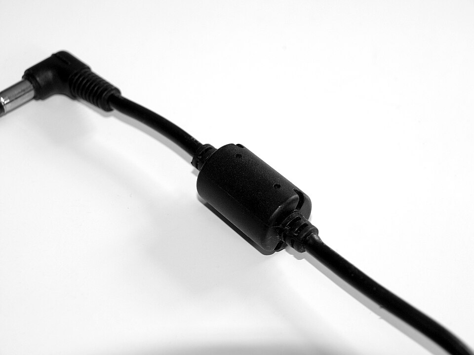
The ferrite bead deserves a mention of its own as the degenerate case: a short NiZn ferrite sleeve slipped over a wire, a one-turn inductor whose whole purpose is to be lossy at RF and turn unwanted high-frequency energy into a trickle of heat. It is the most-used magnetic component in the world and the plainest.
Each shape comes with a matching bobbin or former — the plastic carrier the wire is wound on and the pins the leads terminate to — and the choice of shape therefore reaches straight into the winding volumes, where the bobbins, formers, and mandrels that fit each core are the day-to-day hardware of actually building the coil.
4.8 Temperature, the Curie point, and stability
Every magnetic quantity a core lives by drifts with temperature, and a design that ignores the hot end of its operating range will be a design that fails in the field.
The ceiling is the Curie temperature: the point at which thermal agitation overwhelms the alignment of the magnetic domains and the material stops being ferromagnetic altogether — permeability collapses toward 1 and the core becomes, magnetically, a lump of nothing. For power ferrites the Curie point is uncomfortably close to service temperatures, often 200–250 °C, which is why a shorted or overloaded ferrite that heats without limit can cross its Curie point and lose its inductance entirely — a runaway. Silicon steel (~745 °C) and the nanocrystalline alloys (~570 °C) have no such worry; ferrite does, and the datasheet’s temperature curves are not optional reading.
Well below Curie, two milder effects still bite. First, Bsat falls steadily with temperature — the ferrite that carries 0.5 T cold may carry only 0.35 T at 100 °C — so the saturation margin must always be checked at the maximum operating temperature, not on the bench. Second, permeability itself drifts, quantified by the temperature coefficient of permeability; for a tuned circuit or a precision filter that drift retunes the inductor and detunes the circuit.
The fixes are the ones already met, seen now in a new light. Gapping stabilises a permeability-tuned inductor precisely because it hands control of the inductance from the temperamental material to the fixed geometry of the gap: a gapped core’s effective permeability barely moves when the ferrite’s own permeability wanders. Materials engineered for stability — MPP above all, and the low-µ carbonyl-iron RF mixes — earn their premium here, holding inductance to a fraction of a percent across a wide temperature span. And where absolute stability is the whole point, an air core, with only the thermal expansion of its former to worry about, is unbeatable.
4.9 How to pick a core
Core selection, stripped to its bones, is a short and stubborn sequence, and the families above are simply the menu it draws from.
Begin with frequency, because it eliminates most of the menu at a stroke. Line and audio frequency: silicon steel, or amorphous for efficiency. A switch-mode converter from tens of kilohertz to a megahertz or so: MnZn ferrite for a gapped transformer or choke, or a powder core (sendust, High Flux, MPP) where heavy DC bias rules and a distributed gap is wanted. RF from a few megahertz up: NiZn ferrite or a carbonyl-iron powder mix; above a hundred megahertz or so, often air. Pick a material whose permeability is still flat — and whose loss still low — at the working frequency, which means staying below its knee.
Then size the magnetics to the required inductance and current together. The inductance and the turns follow from the core’s AL value (L = AL·N²); the current sets the peak flux, which must stay below Bsat at the maximum operating temperature with margin to spare, or the inductor saturates. For an energy-storage inductor that usually forces a gap — discrete, in a ferrite, or distributed, in a powder core — to buy the saturation headroom and linearity, at the cost of extra turns.
Weigh the loss budget against that choice: hysteresis plus eddy loss becomes heat, heat must leave the core, and the core’s temperature rise feeds straight back into Bsat and Curie margin. A lower-loss material (MPP, a better ferrite grade) or a larger core buys thermal headroom.
And finally, settle shape, size, and cost. A toroid for containment and efficiency but slow winding; an E-core or bobbin for cheap, fast, machine-wound production; a pot or RM core for shielding and stability. Nickel-bearing powders and nanocrystalline cores buy performance at a real price premium, and for most jobs a ferrite or a sendust core is the honest engineering answer.
Do that in order — frequency, then L and I, then loss, then shape and cost — and the field of candidates collapses from the whole catalogue to a shelf of two or three. The rest is the arithmetic of the design volume, the wire of the conductor volume, and the patient craft of the winding volumes. But the core is chosen first, because everything a coil can and cannot do is decided the moment its material is picked.
Comments (0)