Coils and Coil Winding · Volume 7
The Coil-Winding Machines
7.1 Why a machine exists at all
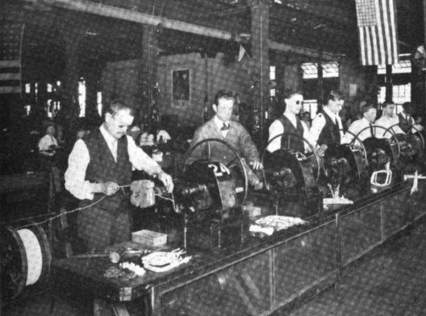
A coil is deceptively simple to describe and infuriating to make well. Wrap enough turns of insulated wire around a form, connect the ends, and you have an inductor — the previous volumes have said as much. But hold a bare spool of magnet wire in one hand and a coil form in the other and try to make two identical coils, and the difficulty arrives immediately. Three things have to go right at once, every single turn, for hundreds or thousands of turns, and the human hand is bad at all three.
The first is counting. Inductance rises with the square of the number of turns, so a coil that is supposed to have 240 turns and actually has 250 is off by roughly eight per cent in inductance before anything else has gone wrong — a miss that would put an RF tuned circuit off frequency or leave a filter choke the wrong value. Counting to several hundred by eye, while also feeding wire, is the sort of task a person fails at reliably. The second is laying the wire: turns want to lie neatly side by side at a controlled spacing, and a hand that wanders leaves gaps, climbs turns over one another, and produces a coil whose length, and therefore whose inductance and self-capacitance, is anybody’s guess. The third is tension: the wire must be pulled taut and, crucially, held at constant tension, because slack turns spring loose and bulge while over-tight turns stretch the copper, crush thin insulation, and can snap fine wire outright.
A coil-winding machine is nothing more, and nothing less, than a device that mechanises those three jobs — turns counting, wire laying, and tension — so that the result is repeatable. That word is the whole point. A one-off experimental coil can be wound by hand and measured afterward; a coil that has to match a design, or match its ninety-nine siblings on the production bench, needs a machine to take the human variability out of the loop. The machine does not make the physics any different; it makes the execution consistent. Even the lone hobbyist, winding one loading coil for one antenna, benefits — not because the coil must match a thousand others, but because the machine lets the builder hit the target turns count on the first try and lay the turns cleanly enough that the finished inductance is close to what the design volume’s formulas predicted.
The machines that do this range from a cast-iron hand crank with a clockwork counter, bought for the price of a nice dinner, up to a servo-driven computer-numerical-control (CNC) cell that costs as much as a car and winds a complex multi-section coil untouched by human hands. They all share the same anatomy, though, and the fastest way to understand any of them — the cheapest hobby winder or the most elaborate industrial machine — is to learn that shared anatomy first and then see how each class elaborates on it.
7.2 The anatomy every winder shares
Strip away the castings and the electronics and every coil winder, from a Morris Coilmaster to a Marsilli automatic cell, is built from the same four functional blocks arranged around one spinning shaft. Learn these four and the rest is detail.
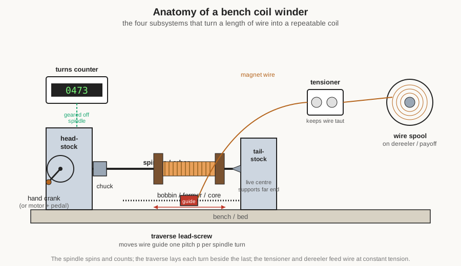
The spindle is the rotating shaft that holds and turns the part being wound. It runs in bearings in the headstock — the fixed casting at the driven end — and it is the axis around which everything else is organised. On a hand winder the spindle is turned by a crank; on a powered machine, by a motor. At the far end a tailstock with a live centre often supports a long form so it cannot whip or sag. Turn the spindle once and the coil form turns once and, by definition, one turn of wire is laid on. Everything the machine does is timed off this one rotation.
The turns counter is geared or coupled to the spindle so that it tallies those rotations. It is the machine’s memory of how far along the job is, and because inductance depends so sharply on turns, it is arguably the single most important part. A hobby machine may have a mechanical odometer-style counter; a production machine has an electronic counter with a preset that stops the spindle automatically on the target count. Either way, the counter is what lets the operator say “wind exactly 312 turns” and get exactly 312.
The traverse (also called the wire-lay or lead) is the mechanism that moves the wire along the coil as it is wound, so that successive turns land next to their neighbours instead of piling up in one spot. It is a small carriage carrying a wire guide — often just a hardened eyelet or a pulley — driven sideways along the coil’s axis. The rate at which it moves, relative to how fast the spindle turns, sets the pitch: the centre-to-centre spacing of adjacent turns. Get the traverse right and the turns lie like thread on a spool; get it wrong and the coil is a lumpy mess.
The tensioner sits in the wire path between the supply spool and the guide, and its job is to keep the wire under steady, controlled pull. Behind it, the supply spool usually rides on a dereeler (or payoff) that lets wire off smoothly and, on better machines, brakes the spool so it does not overrun and dump slack when the machine slows. Tension is the least visible of the four subsystems and the one that most often decides whether a coil comes out tidy or terrible.
That is the whole machine: a shaft that spins and counts, a carriage that lays the wire down evenly, and a feed that keeps it taut. Every class of winder is a different answer to the questions how is the spindle driven, how is it counted, how is the traverse controlled, and how good is the tension. The sections below take each block in turn, then climb the ladder from hand crank to CNC, then look at the special machines and the accessories, and finally at what a real small shop actually needs.
7.3 The spindle, chuck, and arbor: holding the part
Before a machine can wind anything it has to hold the thing being wound and spin it true, and the variety of things a coil shop must grip is surprisingly wide: a moulded plastic bobbin with a square centre hole, a length of ferrite rod, a cardboard tube, a bare toroid ring with no shaft at all, an odd bracket that a transformer bobbin clips into. The spindle end adapts to each with a small family of fixtures.
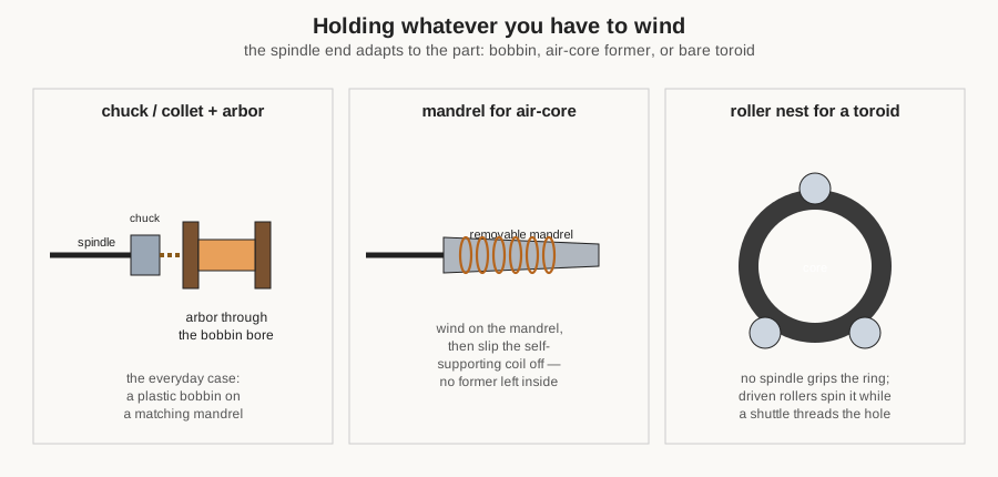
The commonest fixture is an arbor (or mandrel): a shaft, often stepped or tapered to match a family of bobbin bores, that slides through the centre of the part so the part turns with the shaft. A bobbin with a hole simply threads onto its arbor and is clamped between shoulders or by a nut. Where the part has no convenient bore, a chuck — the same jawed gripping device a lathe or a drill uses — clamps onto a spigot or the part itself. For fine or repetitive work a collet, a slotted sleeve that squeezes down uniformly when drawn into a taper, grips a round mandrel more concentrically and repeatably than a three-jaw chuck can.
Two cases deserve their own mention because they recur constantly in coil work. The first is the air-core coil, which by definition has no permanent former inside it — an RF solenoid that must stand on its own turns. It is wound onto a removable mandrel of the finished inner diameter (often lightly waxed or wrapped in paper so the turns release), then, once the ends are secured, slid off the mandrel as a self-supporting helix. The mandrel is a tool, not a part of the coil. The second is the toroid, the ring that torments every coil winder: it has no axis to put a shaft through, because the wire has to pass through its hole on every turn. A toroid is therefore not gripped by a spindle at all but cradled in a nest of driven rollers that spin the ring in place while the wire is fed through the hole — a scheme that leads directly to the toroid shuttle machine discussed later. Beyond these, a well-equipped shop accumulates a drawer of jigs: shaped holders, split arbors, and clip fixtures that let one machine grip the particular odd cores and bobbins that shop happens to wind.
7.4 The turns counter: why counting is everything
If a coil winder had to be reduced to one instrument, it would be the turns counter, because the count is the coil. The design volume’s formulas all turn on N, the number of turns, and most of them on N squared, so counting error propagates straight into inductance error, doubled. A machine that spins beautifully and lays wire like a sewing machine is worthless if the operator loses count at turn 400.
The simplest counter is mechanical: a train of gears, driven off the spindle, turning number wheels like a car’s odometer. The classic hobby winders — the Morris Coilmaster sold through Allied Radio in mid-century America, the many cast-iron hand winders that followed — used exactly this, a worm gear off the crank shaft turning a little drum of digits. It is robust, needs no power, and reads out the running total at a glance. Its limits are that it only counts; it cannot stop the machine, so the operator must watch the drum and quit cranking at the right number, and at speed it is easy to overshoot. Some mechanical counters can be preset to count down to zero from the target, which is easier to watch than counting up, but the operator is still the one who has to stop.
The step up is the electronic counter, which senses each spindle revolution with an optical interrupter (a slotted disc breaking a light beam) or a Hall-effect sensor (a magnet on the shaft passing a solid-state field sensor) and tallies the pulses digitally. This buys three things. It buys a bright, unambiguous digital readout. It buys presets — the operator dials in a target, and when the count is reached the counter can command the motor drive to stop. And on better controllers it buys a slowdown band: the machine runs fast for the bulk of the winding, then automatically decelerates a few turns before the target so it can stop precisely on count without the overshoot that inertia would otherwise cause. A preset counter that decelerates and halts on the exact turn is the feature that turns a fast motor from a hazard into a tool, and it is the heart of every motorised bench winder. Programmable machines take the same idea further, counting turns per section so a coil can have a tap brought out at, say, turn 85 and the winding continued to turn 300 — the counter tracking not one total but a sequence of targets.
7.5 The traverse: laying the wire at a set pitch
The traverse is where a winder stops being a motorised spool and starts being a machine tool, because the traverse is what makes turns lie where the design wants them. Its job is to move the wire guide steadily along the coil’s length in step with the spindle’s rotation, so that as each turn is laid the wire has advanced by exactly one turn’s width — the pitch — and the next turn falls neatly beside it.
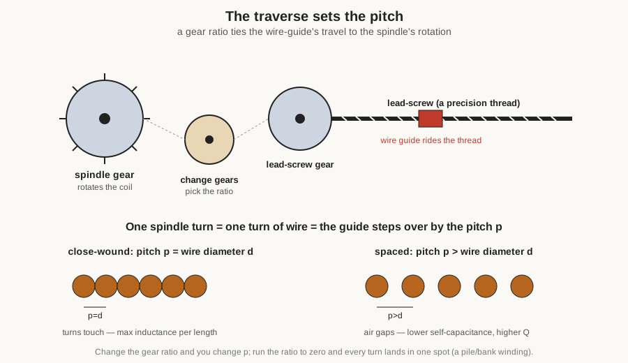
On a mechanical machine the traverse is driven by a lead-screw — a precision threaded rod — coupled to the spindle through a train of change gears. As the spindle turns, the gear train turns the lead-screw, and a nut riding the screw carries the wire guide sideways. The ratio of the gear train, together with the pitch of the lead-screw thread, sets how far the guide moves per spindle revolution. Swap the change gears and the pitch changes: a ratio that advances the guide by exactly one wire diameter per turn gives a close-wound coil, turns touching, packed as tightly as the enamel insulation allows — the maximum inductance for a given length and the natural choice where turns-per-inch matters more than the last few points of quality factor. A ratio that advances by more than a wire diameter gives a spaced winding, air gaps between the turns, which the geometries volume explained lowers turn-to-turn capacitance and proximity loss and so raises Q at radio frequencies. Run the ratio the other way, to essentially no traverse, and every turn piles onto the same spot: a pile or bank winding, the way a stubby high-inductance choke is built.
The change-gear approach is exact and repeatable, but changing pitch means changing gears, which is fiddly, so simpler machines instead use a cam — a shaped groove or plate that pushes the guide back and forth — or a manual traverse, where the operator simply guides the wire by hand or thumb across the turning form, pacing the lay by eye and feel. Hand traverse sounds crude, and for close, uniform single-layer winding it is, but a skilled hand is remarkably good at it and it is how a great deal of small-shop and amateur coil work is actually done: the machine spins and counts, the operator lays.
The real power of the traverse shows up on a programmable machine, where the guide is driven by its own servo or stepper motor rather than a lead-screw geared to the spindle. Now the pitch is a number in software, changeable turn by turn, and the machine can do things a fixed gear train cannot: wind a precise number of layers, reverse the traverse at each end to build up a multilayer coil, lay turns at a slowly changing pitch, step over a controlled distance to start a new section, and even reproduce the crossing, reversing lay of a universal or honeycomb winding — the low-capacitance geometry that once demanded a special cam machine — entirely in code. The traverse is, in short, the axis that separates a machine that can only wind simple bobbins from one that can wind whatever the design volume can specify.
7.6 The tensioner: the quiet subsystem that decides everything
Tension is the subsystem beginners ignore and experts obsess over, because it is invisible until the coil is finished and then it is the first thing that shows. Too little tension and the turns are loose and sloppy: they spring away from the form, bulge, and cross over one another, so the coil’s dimensions — and therefore its inductance and self-capacitance — wander from the design. Too much tension and the trouble is worse: the copper is drawn thinner (necked), its resistance rises, the enamel insulation is scraped or crushed against the form’s edges, thin wire breaks outright partway through a long winding, and a light plastic bobbin or a fragile ferrite can be deformed or cracked by the accumulated squeeze of hundreds of tight turns. What the wire wants is constant tension: enough to seat each turn firmly against its neighbour and the form, the same on turn one and turn one thousand, without slack and without stretch.
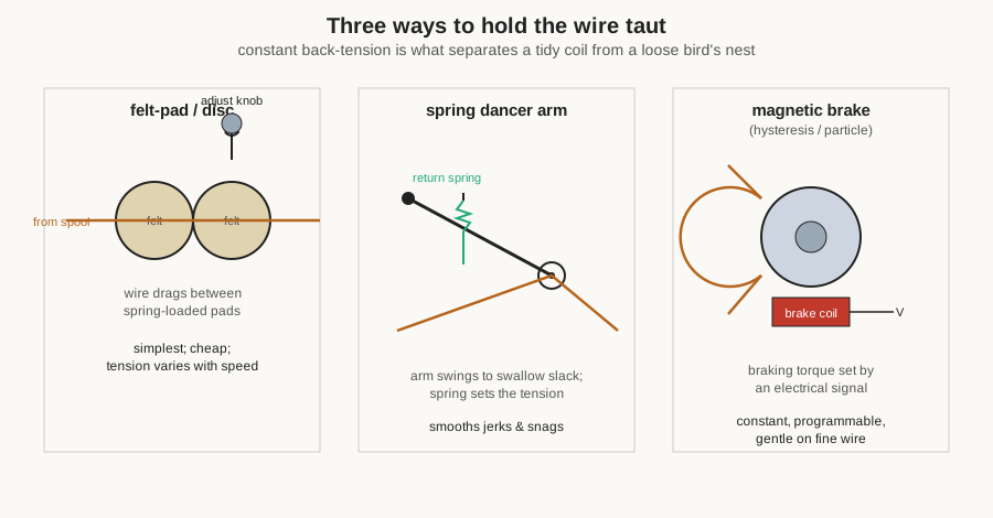
The simplest tensioner is a felt-pad or disc arrangement: the wire is threaded between two spring-loaded pads or discs, faced with felt or a hard smooth material, and a knob sets how hard they pinch. The drag they add is the back-tension. It is cheap, compact, and on countless hobby and bench winders it is entirely adequate. Its weakness is that friction drag depends on speed and on how much wire is left on the supply spool, so the tension a pad tensioner delivers is not truly constant as the machine accelerates and the spool empties. A refinement is the spring dancer arm (or dancer pulley): the wire runs over a pulley on a pivoted, spring-loaded arm that swings to take up slack and give back wire when the pull increases, so the arm mechanically averages out the jerks and snags that would otherwise yank the wire, while the spring sets the nominal tension.
The high end belongs to the magnetic tensioner — a hysteresis brake or a magnetic-particle brake coupled to a capstan pulley the wire wraps around. Here the braking torque is produced not by rubbing pads but by a magnetic field, and it is set by an electrical signal, which gives three advantages the pad cannot: the drag is essentially constant regardless of speed, it can be programmed and even ramped (a useful trick is to taper the tension slightly toward the end of a coil), and there are no friction surfaces to wear, chatter, or damage the finest wire. These sealed magnetic brakes are what production and CNC machines use, often with a load cell measuring the actual wire tension and a controller closing the loop by trimming the brake current. Feeding all of them is the dereeler: the supply-spool holder. A good dereeler brakes the spool so it cannot overrun and spill a loop of slack when the machine decelerates, and on large or fine wire an active, motorised dereeler pays wire off under its own control so the tensioner sees a smooth supply rather than fighting the inertia of a heavy spool. Cheap winders skip the dereeler and let the spool flop on a spindle, which works until it does not.

7.7 Hand winders: the workhorse of the small shop
For the individual builder — the ham radio operator winding a loading coil, the audio hobbyist rebuilding a crossover choke, the experimenter making one RF solenoid — the hand winder is very often the whole answer, and it deserves respect rather than apology. A hand winder is a spindle turned by a crank, a mechanical turns counter geared to that spindle, some means of holding the form, and — on the better ones — a simple lead-screw traverse and a pad tensioner. That is all, and it is enough for a great deal of real work: tens of turns to a few thousand, in any wire a human wrist can pull.
Its virtues are the virtues of simple tools. It is cheap; a serviceable hand winder, new or vintage, costs a fraction of any powered machine. It needs no electricity and makes no noise. Above all it is tactile: cranking by hand, the builder feels the wire’s tension directly through the form, feels a snag or a tight spot the instant it happens, and can pace the traverse and the tension to the wire in a way that is genuinely hard to beat for one-off precision. A patient hand on a good hand winder lays a single-layer RF coil as cleanly as any machine.
Its limits are equally plain. The operator’s arm sets the speed, so a thousand-turn coil is a thousand cranks and a tired shoulder. The traverse is often left to the operator’s other hand, so evenness depends on skill and attention. And because nothing stops the machine automatically, hitting an exact high turn count means watching the counter and quitting at the right moment, with the ever-present risk of a distracted overshoot. None of these is fatal for the volumes and quantities a hobbyist actually works in; they are the reasons a shop that winds many coils reaches for a motor.
7.8 Motorised bench winders: the productivity jump
Put a motor on the spindle and add a preset electronic counter, and the hand winder becomes a motorised bench winder — the machine that most serious small shops and repair benches actually own. The change is not subtle. A variable-speed motor, controlled by a foot pedal so both hands stay free for the wire, spins the form far faster and far more steadily than a wrist can, and the preset counter watches the turn count, decelerates the motor as the target nears, and stops it dead on the number. A coil that took ten patient minutes by hand is wound in under one, and it comes out on count every time because the machine, not the operator, does the stopping.
What the motorised bench winder usually does not automate is the wire lay. Many of them still leave the traverse to the operator — a hand-guided or thumb-paced lay across the spinning form — or provide only a simple, fixed lead-screw traverse. This is a sensible division of labour: the motor and preset counter kill the two most tedious and error-prone jobs (turning and counting), while the human hand, which is good at it, keeps the delicate task of laying the wire. Foot pedal down, watch the wire feed on smoothly, guide the lay, and let the machine coast to its programmed stop. For transformer bobbins, audio chokes, motor coils, and the general run of shop work, a motorised bench winder with a good preset counter and a decent tensioner is the tool that earns its bench space every day. It is, not coincidentally, exactly the class of machine that serves both inductor and transformer winding equally — the same bench winder that lays an RF choke lays a small mains transformer’s primary, a point the transformers dive takes up in detail.
7.9 CNC and programmable winders: where the precision lives
At the top of the ladder is the CNC or fully programmable winder, where a computer commands the spindle motor and one or more traverse motors together, in closed loop, and often the tension as well. Nothing here is new in principle — it is still a spindle, a counter, a traverse, and a tensioner — but every one of those is now a servo-controlled axis coordinated by software, and that coordination is what unlocks coils a geared machine cannot make.
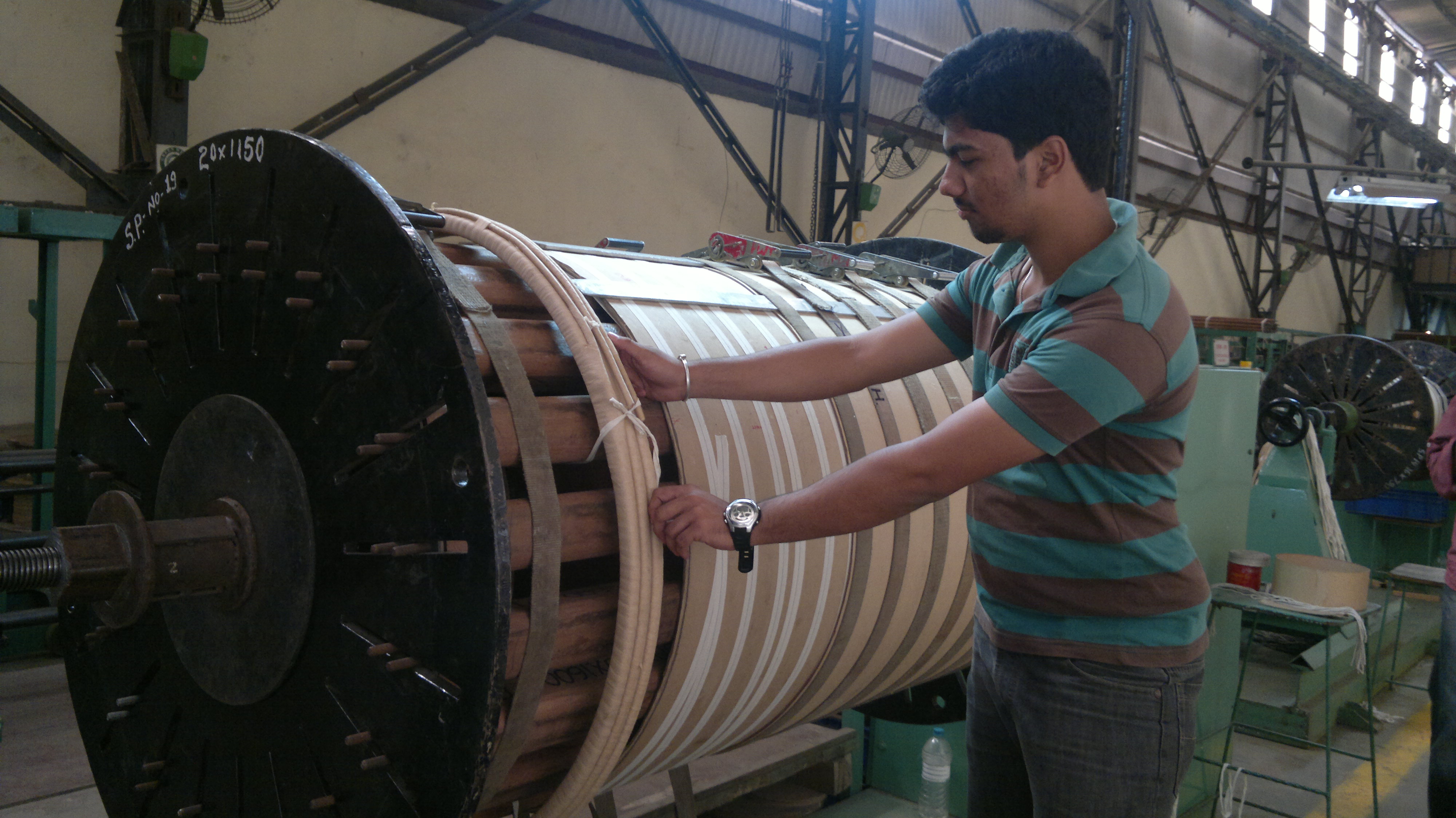
Because the traverse is a programmed axis synchronised to the spindle rather than a fixed gear ratio, a CNC winder can be told, in a stored program: wind this many turns of this pitch to make layer one; reverse and lay layer two; insert an inter-layer step here; bring out a tap at this turn; wind a second, separate section over there; and taper the tension as the coil builds. Complex low-capacitance geometries that once needed dedicated cam machinery — universal, bank, and progressive windings — become recipes the machine executes automatically and, crucially, identically on every coil it makes. A programmable machine will wind a coil with a dozen taps and three interleaved sections, untouched, ten thousand times, each within a turn of the last. That repeatability, and the ability to wind geometries too intricate to lay by hand, is what the money buys.
This is the territory of the specialist machine builders — firms such as Aumann, Marsilli, and Synthesis, and a long tail of makers offering multi-spindle automatic cells, linear (traverse) and flyer winders, and machines dedicated to particular parts. The distinction between “CNC” and merely “programmable” blurs in the catalogues and matters less than the underlying capability: how many axes are coordinated, how the tension is controlled, and how much of the job — wire cutting, terminating, taping, loading and unloading the part — the machine automates around the winding itself. A small shop rarely needs this class of machine, but it is worth understanding, because every feature on a good bench winder is a simplified echo of what the CNC machine does in full.
7.10 Special machines: the toroid winder and its kin
Some coil shapes defeat the ordinary spindle-and-traverse machine, and the winners of that fight are special machines built around the awkward geometry. The most important, and the cleverest, is the toroid winder.
The toroid is the coil that cannot be wound the normal way, because there is no axis to put a spindle through: the wire has to pass through the ring’s central hole on every single turn, and a spool of wire will not fit through the hole. Winding a toroid by hand means cutting a length of wire, threading its whole length through the hole, pulling it snug, and repeating — turn after turn, dragging the entire remaining wire through the donut each time. It is the most tedious job in coil winding, and the toroid winder exists to automate exactly it.
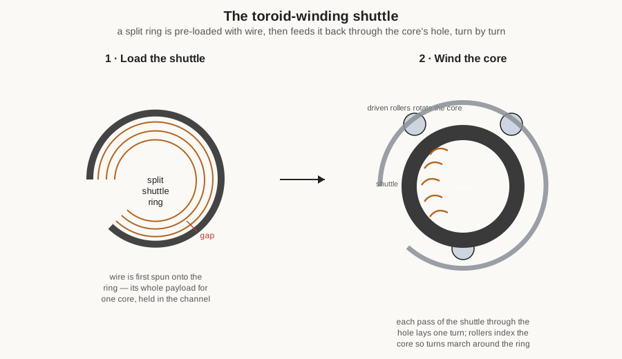
The trick is a shuttle — a split ring, open at one point like a letter C — that is first pre-loaded with all the wire one core will need, spun on in a first operation. The loaded shuttle is then threaded through the toroid’s hole (the gap in the ring lets the core slip on and off), and there it rotates continuously, its open ring passing through the core’s hole on every revolution. Each pass pays a length of wire off the shuttle and lays it as one turn on the core, while a nest of driven rollers turns the core a little between passes so the turns advance evenly around the ring. The genius of the scheme is that the wire no longer has to be dragged, whole, through the hole each turn; it is stored on the shuttle inside the loop of the coil and released turn by turn. A toroid that would take an hour by hand is wound in a minute or two. The costs are that the shuttle must be re-loaded for each core, its capacity limits the wire length (and so the turns and wire gauge) that can be wound in one go, and there must be room to thread the shuttle through the hole — very small toroids remain genuinely hard to machine-wind, which is why the smallest, finest toroids are sometimes still wound by hand.
Beyond the toroid winder sit the other special machines the wider magnetics industry runs: stator and armature winders that lay coils into the slots of motor and generator iron, flyer and needle winders for motor and bobbin coils, and dedicated bobbin winders for the endless small transformers and chokes of consumer electronics. They are outside the scope of a coil-and-inductor shop, but they share the same DNA — a controlled spindle or flyer, a counted turn, a laid wire, a held tension — dressed for a particular part.
7.11 The accessories that make a winder usable
A winder alone is half a workstation; the other half is the tooling around it, and a shop’s real capability often lives in that drawer of accessories more than in the machine itself.
At the supply end are the spools of magnet wire and the dereelers that hold them. A dereeler can be as simple as a free-spinning spindle with a felt drag, or as elaborate as a motorised, tension-sensing payoff for heavy or delicate wire; either way its job is to hand wire to the tensioner smoothly, without the spool overrunning on deceleration or dragging on start-up. Fine wire in particular benefits from a wire straightener — a staggered set of small rollers the wire threads through — which pulls the natural curl of spooled wire out so it lays flat and true, and from guide eyelets of hardened steel, ceramic, or ruby at the points where the wire changes direction, so the moving wire is not sawn against a soft edge.
At the spindle end are the formers, mandrels, and bobbins already discussed, plus the arbors that carry them and the collets and jigs that grip the odd ones. A shop that winds a recurring set of parts accumulates a matched set of arbors and holding fixtures, and building or buying the right holder for a troublesome core is often what turns an “impossible” coil into a routine one. And around the counter live its presets — the means of dialling in target turns, tap positions, and section counts — which on a programmable machine become stored programs recalled by part number. None of these is glamorous; all of them are the difference between a machine that can wind a part and a machine that winds it well, quickly, and the same way every time.
7.12 Choosing and using a winder in a small shop
For the practical question — what does a hobbyist or small shop actually need? — the honest answer is modest. A hand winder with a good mechanical counter and a decent tensioner covers the overwhelming majority of coil and small-transformer work a home builder will ever do: RF solenoids, loading coils, audio chokes, small mains and audio transformers, the odd toroid wound with a hand shuttle or simply by patient hand threading. The tactile control of a hand crank, plus an honest count and steady tension, produces coils as good as the design deserves. If the arm tires or the counts run high, the next rung — a motorised bench winder with a preset, decelerating counter and a foot pedal — is the single most worthwhile upgrade, killing the turning-and-counting tedium while leaving the skilled wire lay to the hand. A CNC or programmable machine earns its keep only when the shop winds either many identical coils or coils too intricate to lay by hand — multi-section, multi-tap, universal-wound parts in quantity — and for most hobby and repair benches it is a want, not a need.
One point is worth underlining because it recurs throughout this project: the same winder serves both inductor and transformer winding. A coil is a coil to the machine; whether its ends go to a tuned circuit as an inductor or across a magnetic core as a transformer primary, the spindle spins it, the counter counts it, the traverse lays it, and the tensioner holds it just the same. The winders described here are precisely the machines the transformers dive relies on for its own windings, which is why a shop set up to wind coils is already most of the way to winding its own transformers.
7.12.1 The bench winders in this shop
The winding volumes of this project are written around real machines: the shop that occasions them keeps one or more coil winders on the bench, used for both the inductors of these volumes and the transformers of the companion dive, and those specific machines — their make and model, their counter and traverse arrangement, and the range of coils they can practically handle — will be featured here with photographs once documented. The technique volume that follows shows these principles in action on real windings; the particulars of the owner’s own machines belong in the placeholders below, to be filled from the bench rather than invented.
7.13 Where this leads
This volume has been about the machines — the anatomy every winder shares, the four subsystems (spindle, counter, traverse, tensioner) each explained, and the ladder from hand crank to motorised bench to CNC, with the toroid shuttle as the clever special case. It has deliberately stopped short of how you actually run one. That is the next volume’s job: the technique of winding — how to count without losing your place, how to set and feel the right tension for a given wire, how to lay clean single layers and build tidy multilayers, how to interleave and tap and anchor and terminate, how to wind a toroid by hand when the shuttle machine is overkill, and the catalogue of mistakes that turn a good machine’s output bad. The wire volume set the tension a given gauge can take and what a machine can pull; the geometries volume said which shapes need which capabilities; and the build-your-own volume puts these machines to work on real projects. Here the machine has been laid out on the bench and taken apart in the mind. Next, the builder picks up the wire and starts to crank.
Comments (0)