Coils and Coil Winding · Volume 12
Measuring and Testing Coils
12.1 The coil on paper is not the coil on the bench
Every previous volume in this set has treated a coil as a design object: choose a core, choose a wire, compute the turns, and out comes an inductor of the intended value. That arithmetic is honest, but it is optimistic. The turns you wound landed imperfectly; they crossed over one another, bunched at the ends, and left a little extra wire at the tap. The core you bought has an inductance factor — the AL value, the nanohenries you get per turn squared — that the manufacturer guarantees only to a tolerance, often ±20% or worse for ferrite. And even a perfect coil does not have one inductance: it reads differently at 120 Hz than at 100 kHz, differently cold than hot, differently at rest than at rated current. A coil, more than almost any other passive part, is a component you have to measure to know.
This volume is the bench half of the story. The [real-inductor volume] explained why an inductor has DC resistance, self-capacitance, a self-resonant frequency, a quality factor, and a saturation limit; here those same quantities are things you put a probe on and read a number for. The goal is practical: to let a hobbyist put a coil across a meter and get a trustworthy inductance, and to let an engineer pin down Q, SRF, and the saturation knee well enough to sign off a power supply. As with any measurement, half the skill is knowing what the instrument is actually doing, because a coil is very good at fooling a meter that is used carelessly.
12.2 Why the multimeter lets you down
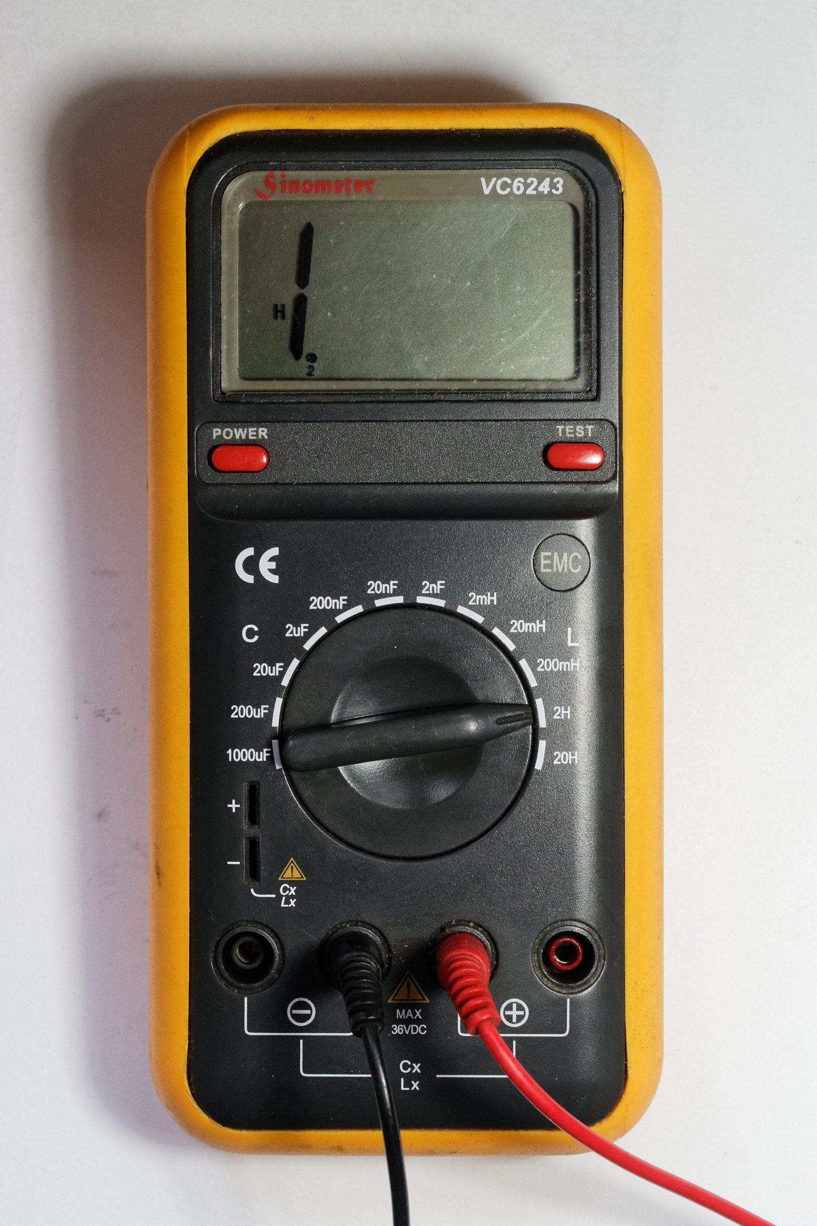
Reach for a typical digital multimeter (DMM) to measure a coil and you will find there is no inductance range on the dial. This is not an oversight. A DMM measures resistance by pushing a known DC current through the part and reading the voltage — Ohm’s law, one number. Inductance is not a DC property at all: an ideal inductor looks like a dead short to DC once the field has settled, so a DC ohmmeter reads only the wire’s resistance and learns nothing about L. To measure inductance you must excite the coil with a changing current and watch how it opposes the change, which means an AC source and phase-sensitive detection — hardware a plain DMM does not have.
What a DMM can do is still useful. Its resistance range reads the coil’s DC resistance (DCR), the ohmic resistance of the copper, provided the coil’s resistance is more than a fraction of an ohm. That single number is a surprisingly good sanity check, discussed later, because a shorted turn or the wrong wire gauge shows up as a DCR that disagrees with the expected value. And its continuity beep confirms the winding is not open. But for the inductance itself, the DMM is the wrong tool.
The next rung up is the cheap LC meter — a handheld or kit instrument, often built around a small microcontroller, that will happily show inductance from a fraction of a microhenry up to tens of millihenries. These are genuinely handy and cost little, but it pays to understand how most of them work, because it defines their limits. The common design does not drive the coil at a chosen frequency and measure impedance the way a real LCR meter does. Instead it makes the unknown coil part of an oscillator — typically an LC or relaxation oscillator with a known on-board capacitor — measures the resulting frequency, and back-computes L from the resonance relation. It is, in effect, an automated version of the LC-resonance method described later in this volume.
That architecture has three consequences the user must keep in mind. First, the test frequency is not yours to choose — it is wherever the oscillator happens to run for the coil under test, usually somewhere in the tens or hundreds of kilohertz, and it drifts as the inductance changes. For an air-core coil that hardly matters, but for a ferrite- or iron-cored coil, whose inductance depends on frequency (below), the value you read may not be the value at your operating frequency. Second, these meters report only inductance — no Q, no DCR, no self-resonant frequency, and no ability to apply a DC bias. Third, their accuracy degrades at the extremes: very small inductances vanish into the meter’s own lead and stray inductance, and large, lossy, or high-self-capacitance coils can pull the oscillator badly or stop it oscillating at all. Treat a cheap LC meter as a fast go/no-go and a rough value, not as the last word.
12.3 The LCR meter: the workhorse
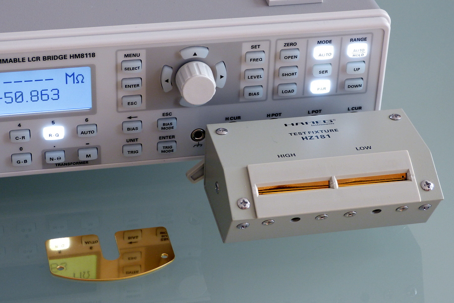
The instrument that actually characterizes a coil is the LCR meter — inductance (L), capacitance (C), resistance (R) — and its bigger sibling, the impedance analyzer. An LCR meter applies a small, known AC voltage or current to the part at a frequency you select, measures the resulting current and the phase angle between voltage and current, and from that complex impedance computes whatever pair of parameters you ask for: L and Q, or L and DCR, or the raw resistance and reactance. Because it measures magnitude and phase, it separates the reactive part of the coil (the inductance) from the lossy part (the resistance) cleanly, which is exactly what a DMM and most cheap LC meters cannot do.
12.3.1 Series versus parallel: which model the meter fits
Here is the first place a coil quietly fools people. A real inductor’s impedance at a given frequency is a single complex number, but that number can be described two equally valid ways: as an ideal inductance in series with a resistance, or as an ideal inductance in parallel with a resistance. The meter cannot tell which picture you have in mind — it just measures the impedance and then reports L and R according to whichever model you selected. Choose the wrong model and the L is still roughly right, but the loss term (and therefore Q or D) can be badly off, and near resonance even L drifts.
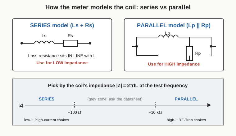
The rule the meter makers give (Hioki, IET/GenRad, Keysight all agree) is to choose by the impedance of the part at the test frequency, because the model’s accuracy depends on which loss dominates:
- Series model for low-impedance parts — roughly 100 Ω and below. That covers small inductances, and any high-current power choke, whose loss is dominated by the series copper resistance. A series model puts the loss resistance in line with the inductance, exactly where the winding resistance physically is, so the series-R the meter reports is close to the real DCR-plus-AC losses.
- Parallel model for high-impedance parts — roughly 10 kΩ and above. That covers large-value RF and iron-cored chokes, especially near or above self-resonance, where the dominant loss (core loss, dielectric loss in the self-capacitance) behaves like a resistance across the coil rather than in series with it.
- The grey zone, roughly 100 Ω to 10 kΩ, is genuinely ambiguous; here you follow the datasheet’s stated measurement conditions or simply report both and note which you used.
For a hobbyist the practical takeaway is short: for the small coils and power inductors you will usually measure, leave the meter in series (Ls-Rs) mode, and switch to parallel (Lp-Rp) only for big high-impedance RF chokes. For an engineer chasing a tight Q or a defensible loss number, the choice is not optional — it is part of the measurement specification, and a Q that looks wonderful in the wrong model can be an artifact.
12.3.2 Test frequency: measure near where the coil will live
The single most important knob on the LCR meter, and the one most often left at its default, is the test frequency. Cheap meters and old bridges default to 1 kHz (or even the 100/120 Hz used for electrolytics); an inductance printed on a datasheet is usually specified at a stated frequency for exactly this reason. The value depends on frequency for two distinct reasons, and both matter.
The first reason is the core. The permeability of ferrite and powdered-iron cores falls as frequency rises — the domains and the material can no longer follow the field as fast — so a cored coil’s inductance, which is proportional to that permeability, falls too. A ferrite choke that reads one value at 1 kHz can read noticeably less at 100 kHz, and this is not meter error; it is the material. Air-core coils, having no such core, are far more frequency-stable in their inductance. The rule that follows is simple and load-bearing: measure the inductance at (or near) the frequency the coil will actually operate at. Measuring a switch-mode power inductor at 1 kHz when it runs at 250 kHz, or an RF coil at 1 kHz when it resonates at 7 MHz, invites a value that is simply not the value the circuit will see.
The second reason is the coil’s own parasitics. As frequency climbs toward the self-resonant frequency, the winding’s self-capacitance resonates with the inductance and the apparent inductance the meter reports rises, heading for infinity at SRF and going negative (capacitive) beyond it. So even setting the core aside, a measurement taken too close to SRF over-reads. The safe habit is to measure well below SRF and near the operating frequency, and — if the two conflict, as they can for a physically large coil used at HF — to note the conditions explicitly.
12.3.3 Test level, and why it can matter
LCR meters let you set the amplitude of the AC test signal (a voltage, sometimes an alternative constant-current setting). For an air-core coil the level is irrelevant — the inductance does not care. For a cored coil it can matter, because ferrite permeability is mildly amplitude-dependent, and because a large AC swing can begin to walk up the B-H curve toward saturation on its own. Manufacturers specify a small test level (often a few tens of millivolts up to 1 V) for repeatability. The practical advice: use a modest, consistent test level, and if you are comparing your reading to a datasheet, match the datasheet’s stated level.
12.3.4 DC bias: measuring the coil under real current
An AC-only measurement tells you the small-signal inductance of a coil sitting idle. A power inductor does not sit idle — it carries a DC load current with the AC ripple riding on top, and that is the condition whose inductance the designer actually cares about. As the DC current rises, the core moves up its magnetization curve toward saturation, the incremental permeability falls, and the inductance drops. The famous consequence is the “100 µH” inductor that is only 60 µH at its rated current — a collapse that can push a converter out of its designed ripple range and into trouble.
To catch this you apply a DC bias during the LCR measurement: a steady DC current is forced through the coil while the meter makes its small-signal AC reading on top. Better bench LCR meters have a built-in bias source (Keysight’s E4980A, for example, offers internal DC bias); many others accept an external DC bias supply or a dedicated bias unit through an isolating fixture that keeps the DC out of the meter’s sensitive front end. Sweeping the bias from zero up to and past the rated current and plotting L at each step produces the L-versus-I curve, the definitive saturation characterization treated in its own section below. For any power-inductor work, an inductance measured without bias is only half the answer.
12.3.5 Four-terminal Kelvin sensing: reading the tiny DCR
Measuring a coil’s DC resistance sounds trivial until you notice that a heavy choke’s DCR might be 10 or 20 milliohms — comparable to, or smaller than, the resistance of the test leads and the contact where the clip meets the wire. A two-wire measurement lumps all of that in and reports nonsense. The fix is four-terminal (Kelvin) sensing: two wires (the force pair) carry the test current to the part, and two separate wires (the sense pair) measure the voltage right at the component’s own terminals. Because the voltmeter draws essentially no current, no voltage is dropped in the sense leads, and the reading reflects only the resistance between the sense contact points — the part itself, not the leads. Bench LCR meters bring the four terminals out as four BNCs; Kelvin clip leads carry the force/sense split all the way to a pair of clips that each have two independent jaws. For milliohm DCR — and for high-Q coils where a tiny series-resistance error swamps the Q number — Kelvin connection is not a nicety, it is the only way to get a true reading. It also underlines why fixturing and clean contacts matter: a bit of oxide or a wobbly clip can add more resistance than the part has.
Reading L, Q, and DCR off the meter, then, is a matter of setting the model, the frequency, the level, the bias if needed, and the connection — and only then trusting the number.
12.4 Q: how good is the coil
Quality factor, Q, is the ratio of a coil’s reactance to its loss at a given frequency — the energy stored per cycle divided by the energy dissipated — and it is strongly frequency-dependent, rising with frequency as reactance climbs, then falling again as AC losses (skin effect, proximity effect, core loss) and the approach to SRF take over. There are three common ways to get it.
The LCR meter gives Q directly: it already knows the reactance and the loss resistance, so Q (or its reciprocal, the dissipation factor D) falls out of the same measurement as L. The caveat is the series/parallel model above — a Q read in the wrong model can be meaningfully wrong — and the Kelvin caveat, since for a high-Q coil the loss resistance being divided into the reactance is small and easily corrupted by lead resistance.
The resonant-bandwidth method is the classic RF-bench approach and needs no fancy meter: resonate the coil with a known capacitor, drive the resulting tuned circuit lightly, sweep frequency, and measure the resonant frequency f₀ and the −3 dB bandwidth BW (the width between the half-power points). Then Q = f₀ / BW. A sharp, narrow response is a high-Q coil; a broad, lazy one is lossy. This is how a grid-dip meter or a VNA effectively measures Q, and it has the virtue of measuring the coil at the actual frequency of interest.
The dedicated Q-meter (the old Boonton-style instrument, and its modern equivalents) automates that resonant method: it resonates the coil against an internal precision variable capacitor and reads Q on a meter directly, and was for decades the tool for RF-coil work. Whatever the method, always report the frequency with the Q — a bare “Q = 120” is meaningless without it.
12.5 Self-resonant frequency: where the coil stops being a coil
Every real winding has capacitance between its turns and layers, and that stray capacitance sits in parallel with the inductance. At the self-resonant frequency (SRF) the two resonate: the inductive reactance and the capacitive reactance cancel, the net reactance passes through zero, and the coil’s impedance magnitude reaches a sharp peak (for the parallel self-resonance of an ordinary winding). Above SRF the “inductor” is actually capacitive and no longer does its job. Knowing SRF matters because you want it comfortably above your operating frequency — a common rule of thumb is to keep the operating frequency below roughly a tenth of SRF so the coil still behaves as an inductor with margin to spare.
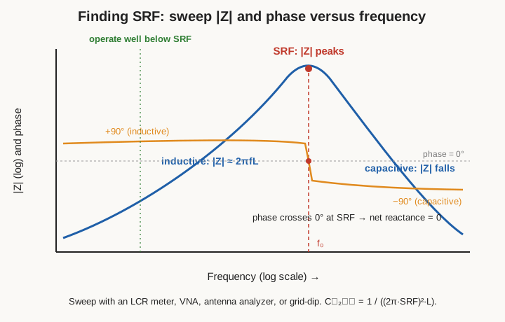
You find SRF by sweeping and watching for that signature — the impedance peak, or equivalently the phase crossing zero. Several instruments will do it:
- An LCR meter or impedance analyzer with a frequency sweep plots |Z| directly; the peak is SRF. This is the most direct laboratory method.
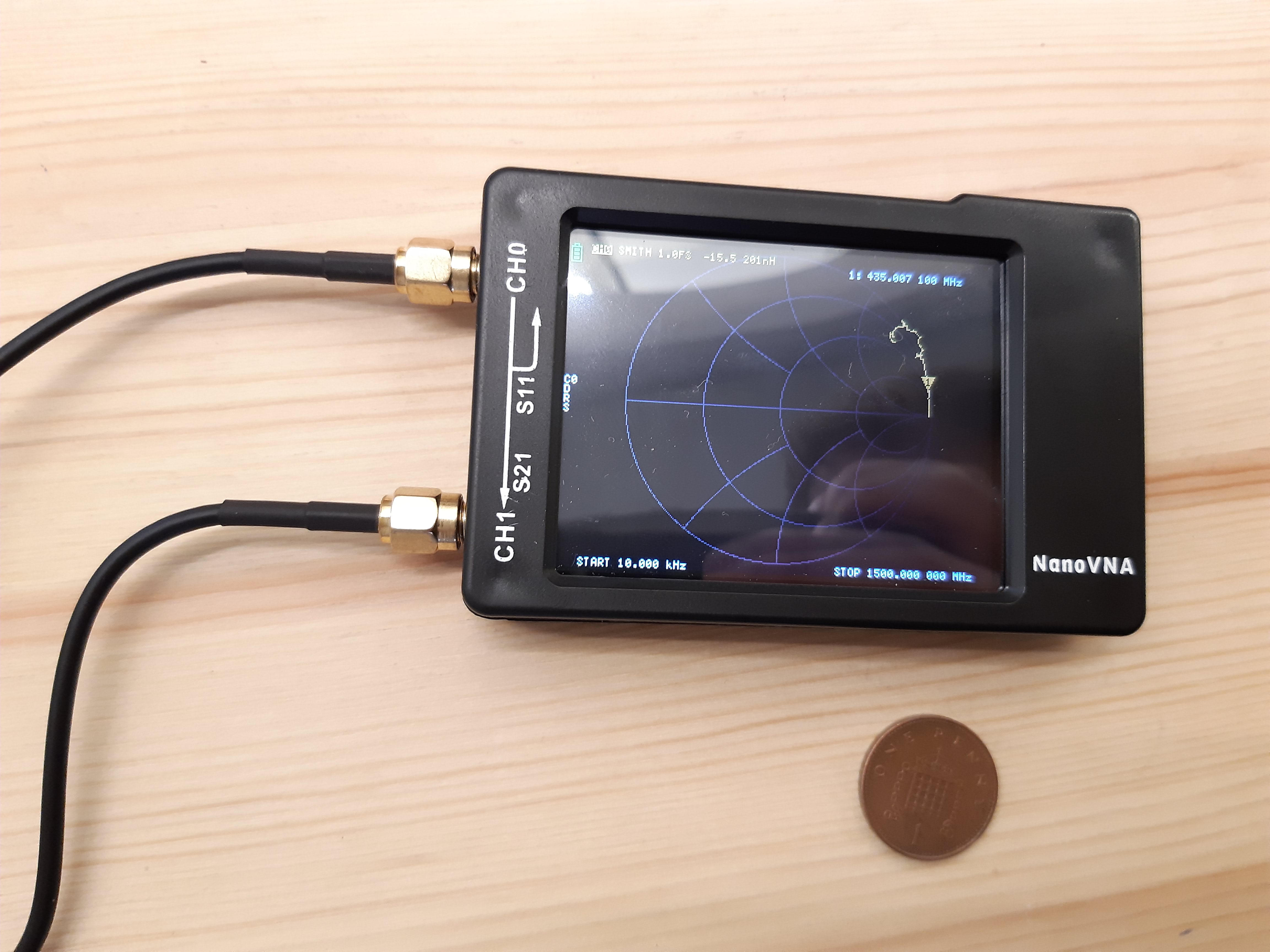
- A vector network analyzer (VNA), including the inexpensive hobbyist NanoVNA, measures the reflection or transmission of the coil in a fixture across a wide sweep; the resonance shows as an |Z| peak or a phase zero-crossing. Coilcraft and Analog Devices both document the VNA method as the reference technique.
- An antenna analyzer (a ham-radio SWR/impedance analyzer) does much the same across the HF/VHF range and is a common, affordable substitute.
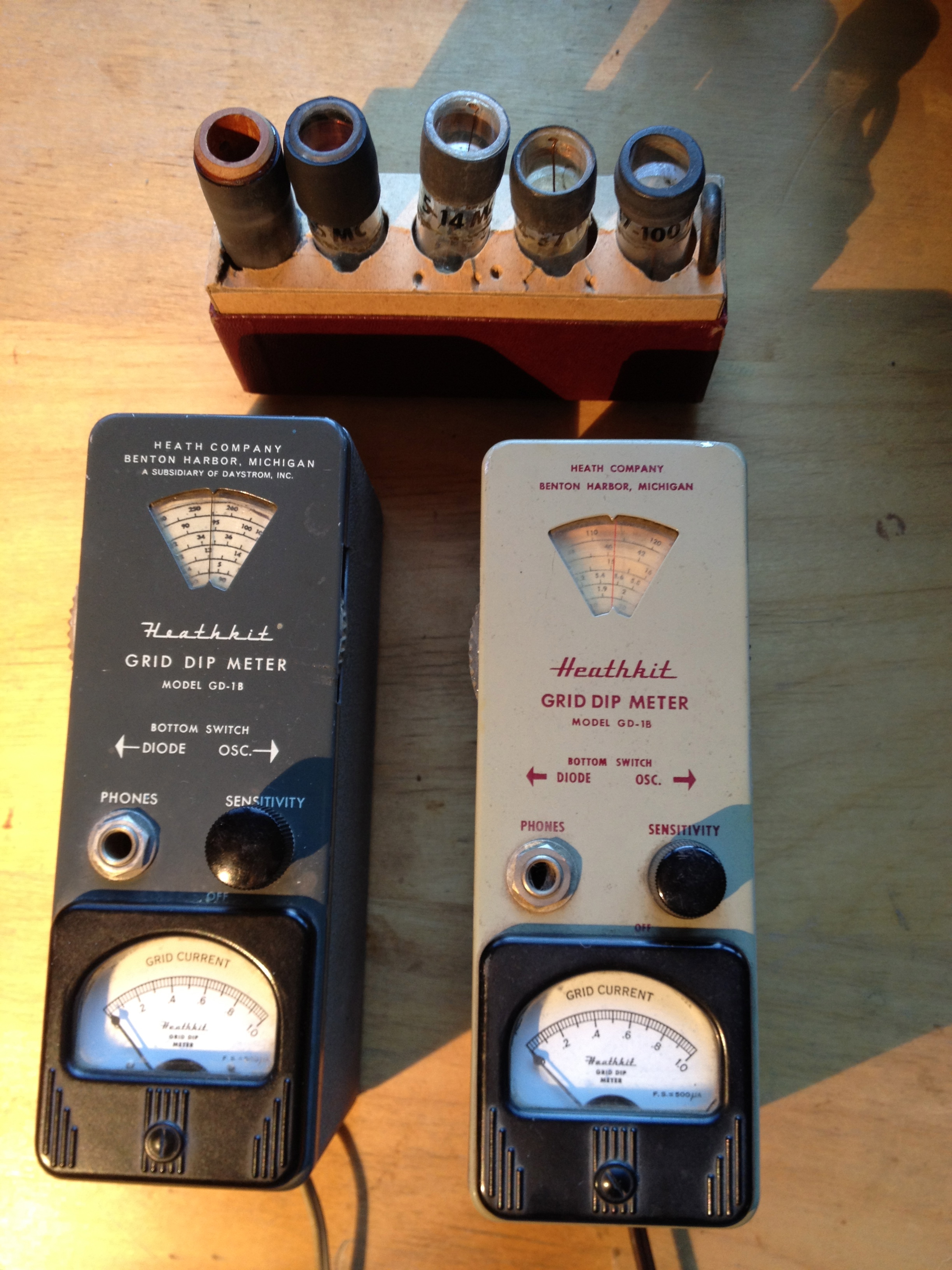
- A grid-dip meter — the vintage classic — is a tunable oscillator with a coil you couple loosely to the coil-plus-known-capacitor under test; at resonance the circuit absorbs energy and the meter dips, and you read the frequency off the dial.
Once you have both the low-frequency inductance L and the self-resonant frequency fSRF, the stray winding capacitance falls out of the same resonance relation that defines SRF: since fSRF = 1 / (2π√(L·Cstray)), rearranging gives Cstray = 1 / ((2π·fSRF)²·L). Measure L on the LCR meter, find SRF on the VNA, and you have a number for the self-capacitance you otherwise could only estimate — a genuinely useful cross-check on a winding whose distributed capacitance you are trying to keep low.
12.6 Saturation and Isat: the L-versus-I curve
For any inductor that carries real current — power-supply chokes, filter inductors, flyback primaries — the most important test is not the idle inductance but the saturation behavior: how far you can push DC current before the core saturates and the inductance collapses. The measurement is the DC-bias sweep introduced above, plotted out in full.
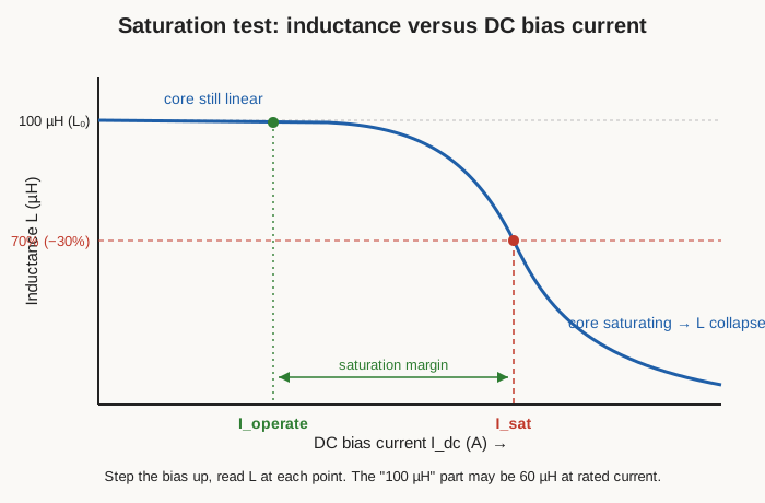
Step the DC bias current up from zero, reading L at each level, and the curve tells the story: L stays essentially flat while the core is in its linear region, then bends through a knee and rolls off steeply as the core saturates and its incremental permeability falls toward that of air. The saturation current, Isat, is defined as the current at which the inductance has fallen by a stated fraction of its zero-bias value — manufacturers variously use −10%, −20%, or −30%, so the definition must always be quoted. The design’s job was to keep the peak operating current safely below that knee, on the flat part of the curve, with a saturation margin to spare; this test is how you confirm the design’s margin survived the real core and the real turns.
Two refinements matter for rigor. First, for coils that see brief high peaks (a flyback running in discontinuous mode, an inrush choke), a slow stepped-DC measurement can be misleading because the core heats and behaves differently under a fast pulse. A pulsed saturation method — driving the coil with a controlled current ramp and watching the current waveform bend upward as inductance falls (di/dt increases when L drops) — captures the dynamic knee and avoids overheating the part during the test. Second, saturation is temperature-sensitive: ferrite saturates at a lower flux density when hot, so a choke that passes a cold-bench saturation test can saturate in a warm enclosure. Serious characterization repeats the L-versus-I curve at the expected operating temperature.
12.7 Turns, shorts, and faults
A wound coil can be wrong in ways that inductance alone will not reveal, so a complete bench check goes after the winding itself.
12.7.1 Backing out the turns from a known core
If you wound a toroid or a gapped core whose inductance factor AL you trust, you can verify the turn count from the measured inductance, because L = AL·N². Rearranged, N = √(L / AL). Measure L on the meter, divide by the core’s AL, take the square root, and compare to the turns you believe you wound. A count that comes out at 47 when you meant to wind 50 tells you the winding is short a few turns — or that the core’s AL is off at the low end of its tolerance, which is the other side of the same coin and exactly why measuring matters. Run in reverse, this is also how you measure an unknown core’s AL: wind a known number of turns, measure L, and solve AL = L / N². Ten turns on a mystery toroid and one LCR reading tells you what the core will do per turn.
12.7.2 The DCR sanity check
The DC resistance you can read on any decent ohmmeter (with a Kelvin connection for the low values) is a blunt but powerful fault detector. Compare the measured DCR against the expected value — wire length times the ohms-per-metre for the gauge, a figure the [wire volume] tabulates. A DCR that is far too high points to the wrong (thinner) wire gauge, a partial break, or a bad joint; a DCR that is too low can mean fewer turns than intended or heavier wire than specified. And a single shorted turn — the most insidious coil fault — often barely changes the inductance (one turn out of hundreds) while it wrecks performance, so DCR and inductance together may look almost normal even though the coil is ruined. That is precisely why the next test exists.
12.7.3 The ring test: the shorted-turn detector
The ring test (or ringdown test) is the classic, cheap, and remarkably sensitive way to find a shorted turn that inductance measurements miss. The idea is a direct application of Q: excite the coil with a brief pulse while a low-loss capacitor sits across it, and the coil-and-capacitor tank rings — a decaying sinusoid whose rate of decay is set by the circuit’s losses, that is, by its Q. A good, healthy coil has high Q and rings for many cycles, the amplitude decaying slowly. A coil with even one shorted turn has a single-turn short-circuit coupled to the whole winding — a heavy, lossy load reflected into the tank — its Q collapses, and the ringing dies out in one or two cycles.
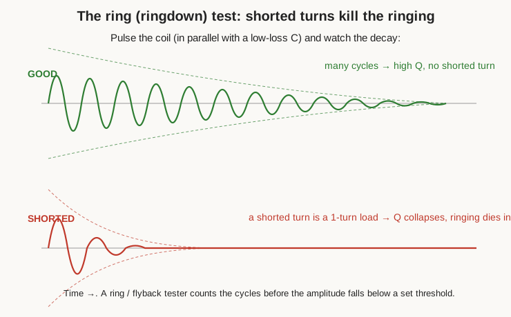
The beauty of the test is what it detects: not the inductance, which a shorted turn barely moves, but the loss, which a shorted turn dominates. Commercial ring testers and flyback (LOPT) testers — the staple of television and monitor repair — do exactly this, pulsing the winding and counting the number of rings before the amplitude falls below a threshold; a low count condemns the part. The same principle works on the bench with a signal generator or a simple pulse circuit, the coil, a good capacitor, and an oscilloscope: count the cycles. It is arguably the single most useful qualitative test for a coil you have just wound and suspect, and it needs almost no equipment.
12.7.4 Continuity and insulation
Finally, the winding’s insulation. Basic continuity confirms the coil is not open and that a tapped or multi-winding coil is connected the way you think. For coils that will see meaningful voltage — mains transformers, flyback secondaries, anything with a high-voltage output — a hipot (high-potential) or insulation-resistance test applies a high test voltage turn-to-core and winding-to-winding to prove the enamel and the layer insulation will hold off the working voltage without breaking down. This is a safety test, not a performance one, but on a coil destined for a high-voltage or line-connected role it is the test that keeps the smoke inside.
12.8 Homebrew and low-cost methods
Not everyone has a bench LCR meter and a VNA, and for a great deal of coil work the classic homebrew methods are entirely adequate. They also teach what the fancy meter is doing under the hood.
12.8.1 The LC-resonance method
The most useful no-LCR-meter technique is the LC-resonance method, and it is exactly how most cheap LC meters work internally. Put a known, good capacitor in parallel with the unknown coil to form a tuned circuit, drive it lightly from a signal generator (through a small coupling resistor or a light coupling, so as not to load the resonance), sweep the frequency, and watch the response on a scope or detector. At the resonant frequency f₀ the tank’s response peaks. Then the inductance follows from the resonance relation:
L = 1 / ( (2πf₀)² · C )

A few practicalities make it accurate. Use a capacitor whose value you know well (a 1% film or C0G/NP0 ceramic), and choose it large enough that the coil’s own self-capacitance is a negligible addition — otherwise you are measuring L against C-plus- stray and reading slightly high. Couple loosely so the source and detector do not spoil the resonance. Pick a C that puts f₀ near the coil’s intended operating frequency, so you are measuring L where it matters. Done with care, this method rivals a mid-range LC meter and, unlike a cheap meter, lets you choose the frequency.
12.8.2 The grid-dip and antenna-analyzer methods
The grid-dip meter does the resonance method with the roles swapped: it is itself a tunable oscillator, and you couple its coil loosely to your coil-plus-known-capacitor tank. When the dipper’s frequency matches the tank’s resonance, the tank steals energy and the meter reading dips; read f₀ off the dial and apply the same formula. It is a lovely one-hand instrument for RF coils and, with a known capacitor, doubles as an inductance meter.
A modern antenna analyzer or NanoVNA does the same job with a digital readout and far more convenience, sweeping the frequency automatically and showing the resonance or the impedance curve. For a ham or hobbyist who already owns one, it is the fastest path to both L (via resonance with a known C) and SRF (of the coil alone).
12.8.3 The signal-generator, scope, and known-resistor method
A third homebrew approach measures reactance directly at a frequency of your choosing. Put the coil in series with a known resistor R, drive the pair from a signal generator at frequency f, and measure the AC voltage across the coil and across the resistor with a scope. The resistor voltage gives the current (I = VR / R); the coil voltage divided by that current gives the coil’s impedance magnitude |Z|; and since |Z| = √(DCR² + (2πf L)²), you subtract out the (usually small) DC resistance and solve for the reactance and hence L = √(|Z|² − DCR²) / (2πf). Pick R comparable to the coil’s reactance for the best sensitivity, and choose f at your operating frequency. The 50 or 60 Hz line-frequency variant of this — driving the coil from a known AC voltage through a known resistor and using the mains as the source — is an old trick for large iron-cored chokes and transformer windings, whose inductances are large enough to show a healthy reactance even at 60 Hz. It is crude, but for a big smoothing choke it works with nothing but a multimeter and a resistor.
12.9 Common pitfalls
Coils punish careless measurement in a handful of repeatable ways, and knowing them is most of the battle:
- Wrong frequency. Measuring a cored coil far from its operating frequency gives a value the circuit will never see, because the core’s permeability — and thus L — is frequency-dependent. Match the test frequency to the application.
- Ignoring DC bias. An idle small-signal inductance flatters a power inductor that will droop badly under load. If it carries current, measure it under bias.
- Lead inductance and hand capacitance. For small inductances (sub-microhenry) the test leads add inductance of the same order as the part; for high-frequency and high-impedance measurements, the capacitance of your hand or a nearby object near the coil shifts the reading. Keep leads short, keep your hands off, and fixture the part.
- No compensation. Every serious LCR measurement starts with open and short compensation (and “load” compensation for the best meters): with the fixture open the meter nulls its stray capacitance, and with the fixture shorted it nulls its residual lead inductance and resistance. Skipping this is the number-one cause of small-value errors. Zero the meter before you trust it.
- Poor fixturing and dirty contacts. A wobbly clip, an oxidized lead, or a long loop of wire adds resistance and inductance that the meter faithfully reports as if it were the part. Kelvin-clip the low-DCR parts and keep the connection tight and clean.
12.10 A workflow: verifying what you built
Pulling it together, here is a sane order of operations for a coil you have just wound, tying the bench back to the [design volume] that specified it and the [winding-technique volume] that shaped it:
- Continuity and DCR first. Confirm the winding is not open, then read the DCR (Kelvin for low values) and compare it to the expected wire-length resistance. A gross disagreement means wrong gauge, a bad joint, or a break — fix that before measuring anything else.
- Inductance at the operating frequency. Set the LCR meter to the series or parallel model appropriate to the coil’s impedance, set the test frequency to (or near) the operating frequency, a modest level, and read L. Compare to the design target; for a cored toroid, cross-check the turns via N = √(L/AL).
- Q, if it matters. For an RF or resonant coil, read Q at the operating frequency and compare to the design’s assumption; a low Q points to lossy wire, a lossy core, or — see step 5 — a fault.
- SRF, if it matters. For anything used at high frequency, sweep for SRF on a VNA or analyzer and confirm it sits comfortably above the operating frequency, ideally by an order of magnitude.
- Ring test for shorted turns. If the DCR or Q looks even slightly wrong, or as a routine check on a suspect winding, ring the coil and count the cycles. A fast decay condemns it regardless of what the inductance says.
- Saturation under bias, for power parts. Sweep the DC bias and plot L-versus-I; confirm Isat and the saturation margin against the design, ideally at operating temperature.
- Insulation, for high-voltage parts. Hipot the winding-to-core and winding-to-winding if the coil will see significant voltage.
The measured coil that passes all the relevant steps is, at last, the coil the design asked for. The [core volume] and the [wire volume] explain why the numbers drift with frequency, temperature, and gauge; this volume is how you catch the drift on the bench — and how you turn a coil you think you wound into one you know you built. The [build-your-own volume] puts these tests to work on real projects, measuring each coil as it comes off the winder and holding it to the number on paper.
Comments (0)