Resistors · Volume 1
What a Resistor Is: Resistance, Ohm's Law, and the Divider
1.1 The One-Sentence Answer, and Then the Everyday One
A resistor is a component that opposes the flow of electric current, turning the electrical energy it takes in into heat. That is the sentence to carry away if only one sentence survives. Everything else in this volume — and, arguably, in the thirteen that follow — is an unpacking of it: what “opposes the flow of current” actually means, why that opposition is such a useful thing to have on hand, why a part whose entire purpose is to waste energy is nonetheless the single most common component in electronics, present by the dozen in almost every circuit ever built.
The everyday physical reality is even simpler than the sentence. Take a small quantity of a material that conducts electricity poorly — a thin film of carbon, a whisker of nickel-chromium wire, a dab of metal-oxide paste fired onto a ceramic chip — give it two terminals, and seal it in a body the size of a grain of rice or a matchstick. That is a resistor. Push a voltage across its two ends and a current flows through it, but only grudgingly, in an amount set by how much the material resists. The current that does get through has to shove its way past countless collisions inside the material, and every one of those collisions surrenders a little energy as heat. The resistor warms up, faintly or fiercely depending on how hard it is worked, and in exchange it gives the designer precise control over how much current flows and what voltages appear where. Control, purchased with heat: that is the whole bargain.
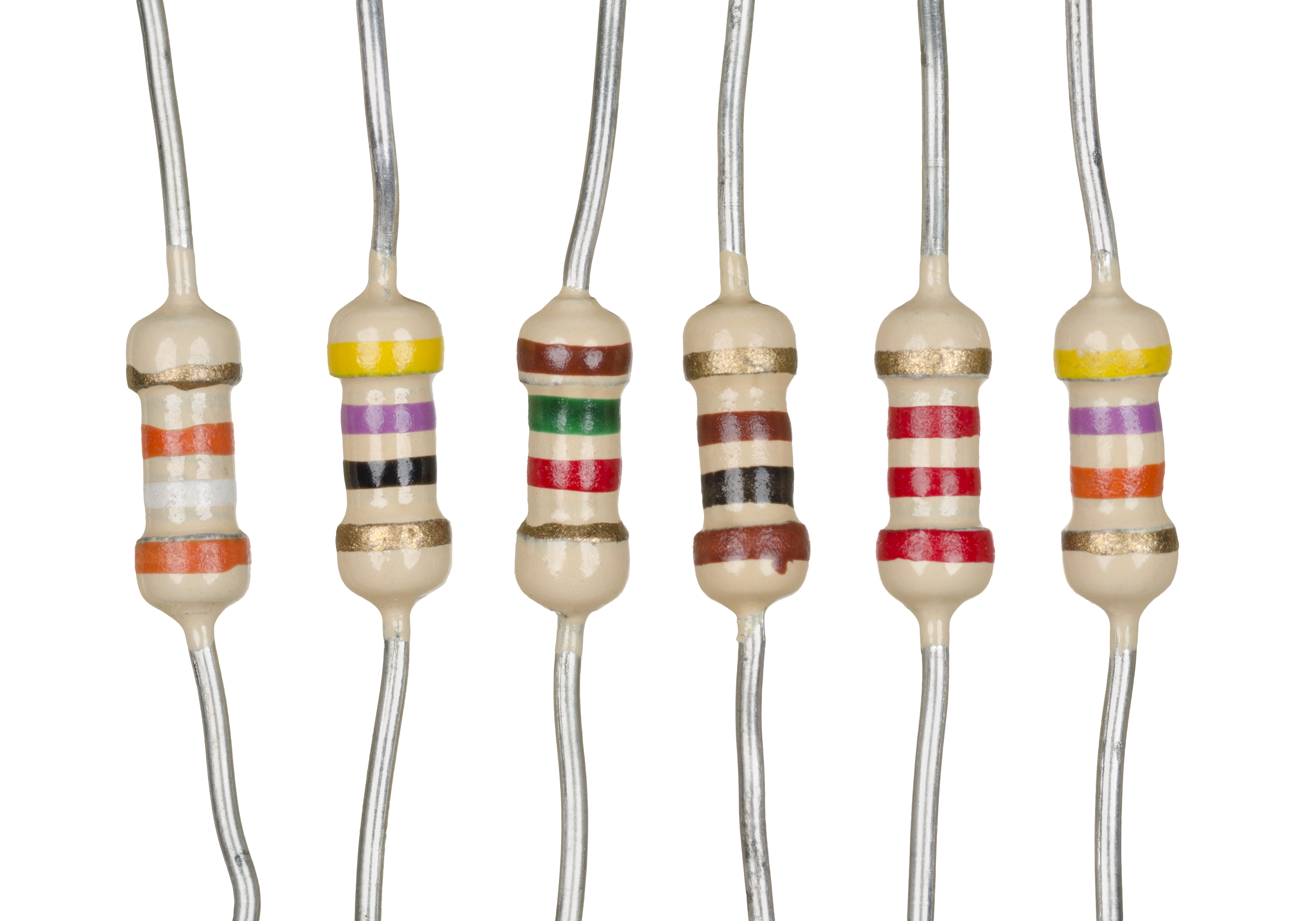
The photograph is a fair introduction to how ordinary these things are. Six little cylinders, each with a lead sticking out of either end and a handful of colored stripes around the body, and every one of them doing the same thing in a slightly different amount. They cost pennies, they come in bags of a hundred, and a modern circuit board may carry several hundred of them without anyone giving the matter a second thought. And yet the resistor repays attention, because the physics it embodies is the physics every other component is measured against, and because getting its handful of equations into the bones turns the rest of the subject from a bag of tricks into a story that makes sense.
1.1.1 The Passive That Dissipates
It helps, from the first page, to hold the resistor up against its two closest relatives, because the contrast defines it. The three fundamental passive components — passive meaning they contain no source of energy and cannot amplify, only shape what is handed to them — are the resistor, the capacitor, and the inductor. A capacitor stores energy in an electric field, in the gap between two conductors, and it releases that energy back to the circuit unchanged when called upon; it resists a change in voltage. An inductor stores energy in a magnetic field, around a coil of current-carrying wire, and likewise gives that energy back; it resists a change in current. Both are, in the ideal, lossless: they borrow energy and return it.
The resistor is the odd one out, and its difference is its identity. It stores nothing. Whatever energy it takes from the circuit it converts, irreversibly, into heat, and that heat radiates away and is gone. The resistor is the only one of the three that dissipates rather than stores, and this single fact is the source of nearly everything that distinguishes it. Because it stores no energy in a field, it has no reactance — the frequency-dependent, energy-juggling opposition that gives capacitors and inductors their character and their phase shifts. A resistor treats a slow signal and a fast signal alike (to a first approximation — later volumes will find the small print). Its opposition to current is the same whether the current is direct or alternating, whether it flows for an hour or for a nanosecond. That plainness, that refusal to store and give back, is exactly what makes the resistor the reliable, predictable, do-what-it-says building block that it is. It is the fixed reference against which the more temperamental components are understood.
Two companion deep dives in this same series treat the storing siblings at length — one on the capacitor, one on the coil — and much of what one learns about any of the three illuminates the other two. Where those volumes reach for stretched membranes and spinning flywheels to explain energy held in reserve, this one reaches for friction: the resistor is the brake, not the spring or the flywheel. Keep that image in the back of the mind. It pays dividends all the way through.
1.2 Ohm’s Law: the Rule That Ties It All Together
If a single equation deserves to be tattooed on the inside of an electronics worker’s eyelids, it is this one. The German schoolteacher Georg Simon Ohm published it in 1827, after painstaking experiments with wires of different lengths and thicknesses, and it states a relationship so clean it feels almost too simple to be a law of nature: the current through a resistor is directly proportional to the voltage across it, with the resistance as the constant of proportionality. In symbols:
V = I × R
Here V is the voltage across the resistor, measured in volts; I is the current through it, measured in amperes (amps); and R is the resistance, measured in ohms. The equation is a statement about cause and consequence in a circuit. Apply a voltage V across a resistance R and a current I is forced to flow, its size fixed by the ratio of the two. Double the voltage and the current doubles. Double the resistance and, for the same voltage, the current halves. Nothing about it is negotiable; it is arithmetic.
Because it is arithmetic, the one equation is really three, and fluency means being able to slide between them without thinking:
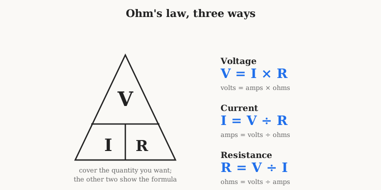
The three forms answer the three questions a designer actually asks at the bench. V = I × R answers “how much voltage will appear across this resistor when a known current flows through it?” — the everyday act of a current dropping a voltage, which is the beating heart of the voltage divider met later in this volume. I = V / R answers “how much current will flow if I put this voltage across this resistance?” — the question behind every current-limiting resistor. And R = V / I answers “what resistance do I need to get the current I want from the voltage I have?” — the design question, the one that tells the builder which part to reach for. The “magic triangle” in the figure is a memory aid, nothing more: write V on top, I and R side by side beneath, cover the letter you are solving for, and the surviving two fall into the right arrangement. Old hands do not need it, but no one is embarrassed to have learned it.
1.2.1 The Water Analogy, Done Properly
The oldest teaching aid for Ohm’s law is a plumbing one, and it is genuinely useful as long as its limits are respected. Picture water flowing through pipes. Voltage is like pressure — the push that drives the water along, the difference in “height” or “head” between two points. Current is like the flow rate — the actual quantity of water passing a point each second. And resistance is like a narrow constriction in the pipe — a pinch, a partly-closed valve, a length of gravel-packed tube that the water must struggle through. Raise the pressure (voltage) behind a fixed constriction and more water flows (more current): that is I = V / R. Pinch the pipe tighter (raise the resistance) at fixed pressure and the flow drops: same equation, read the other way. Widen the pipe to nothing — a fat copper wire, near-zero resistance — and water gushes through for the slightest pressure, which is why a wire carries large currents at tiny voltages, and why shorting a battery across a bare wire is a bad idea.
The analogy even carries the energy story. The water forcing its way through the constriction rubs and churns and, in principle, warms slightly; the resistor forcing current through its poorly-conducting material warms in just the same way, and that warmth is the dissipated energy. So far, so good. But every analogy has a fence around it, and it is worth walking the fence now so the reader is not misled later. Water has substantial inertia and real mass, which map onto the electrical world’s inductance and give behaviors a plain resistor does not have. Real pipes have some springiness and can store a little water under pressure, which maps onto capacitance. A resistor has neither inertia nor springiness in the analogy’s sense — it is pure constriction, pure friction, no storage — which is precisely the “dissipates, does not store” point from the previous section restated in plumbing. Push the water picture too far, especially into alternating current and rapidly changing signals, and it quietly breaks. Held to steady flows through simple constrictions, it is one of the best intuitions in all of engineering.
1.2.2 Ohmic and Non-Ohmic: When the Law Holds
There is one honest caveat buried in Ohm’s law, and it is worth stating plainly because beginners are rarely told it. The law assumes that R is a constant — that the resistance does not itself change when the voltage or current changes. A material or device for which this is true, so that a graph of current against voltage is a straight line through the origin, is called ohmic or linear. An ordinary resistor is designed specifically to be ohmic across its whole normal operating range: plot current against voltage and you get a ruler-straight line whose slope is 1/R. That straightness is a manufactured virtue, the result of choosing materials and constructions that behave the same at every voltage.
Plenty of the electrical world is non-ohmic, and the distinction matters. A diode passes current freely one way and blocks it the other — its I-V curve is a swooping exponential, nothing like a straight line, and “the resistance of a diode” is a question with no single answer. An incandescent lamp filament is ohmic only if you hold its temperature still; in real life its resistance climbs steeply as it heats, so a cold bulb momentarily draws a large inrush current that tapers as the filament glows. A thermistor is built to change resistance dramatically with temperature, and a varistor to collapse its resistance when the voltage across it exceeds a threshold — both are non-ohmic on purpose, and both appear later in this series as useful members of the extended resistor family. The point for now is simply this: Ohm’s law is a law about a constant resistance, and the ordinary resistor is the component engineered to make that constant real. When a device refuses to hold R constant, it has not broken Ohm’s law so much as stepped outside its jurisdiction.
1.3 The Ohm, and the Enormous Range of Values
The unit of resistance is the ohm, named for Georg Ohm and written with the Greek capital omega, Ω. Its definition falls straight out of the law: one ohm is the resistance that lets exactly one ampere flow when one volt is applied across it. One volt, one amp, one ohm — the three units are locked together by V = I × R, and fixing any two fixes the third. A component of one ohm is a rather low resistance in everyday electronics; a single AA cell of 1.5 volts across it would try to push a hefty 1.5 amps.
What surprises newcomers is the sheer range of resistances that real circuits call for. Useful resistors span more than twelve orders of magnitude — from a few thousandths of an ohm up to thousands of millions of ohms — and each region of that range has its own home and its own name. Engineers navigate it with the standard metric prefix ladder, and being fluent in the ladder is as basic as knowing that a kilometre is a thousand metres.
Table 1 — The Ohm, and the Enormous Range of Values
| Prefix & symbol | Multiplier | Typical resistance | Where it lives |
|---|---|---|---|
| milliohm (mΩ) | 0.001 Ω | 1 mΩ – 999 mΩ | current-sense shunts, PCB trace and contact resistance, motor windings |
| ohm (Ω) | 1 Ω | 1 Ω – 999 Ω | current-limiting, LED and base resistors, low-value damping |
| kilohm (kΩ) | 1 000 Ω | 1 kΩ – 999 kΩ | pull-ups and pull-downs, biasing, voltage dividers — the busiest decade of all |
| megohm (MΩ) | 1 000 000 Ω | 1 MΩ – 999 MΩ | high-impedance inputs, timing networks, bleeder resistors, gate leaks |
| gigaohm (GΩ) | 1 000 000 000 Ω | 1 GΩ and up | electrometer and photodiode front-ends, insulation, feedback in charge amplifiers |
A few practical notes travel with that table. The kilohm decade is where the great mass of ordinary resistors live — pull-up resistors on logic lines, the resistors that set the gain of an amplifier or the bias of a transistor, the two resistors of a garden-variety voltage divider. If a designer had to guess the value of a random resistor plucked from a working circuit, “a few kilohms” would be the smart bet. Down at the milliohm end, resistance becomes so small that the ordinary two-wire way of measuring it fails, because the resistance of the measuring leads themselves swamps the tiny value being measured; a whole four-terminal measurement technique exists to cope, and a later volume is devoted to it. Up at the megohm and gigaohm end, the resistance becomes so large that stray leakage across a dusty or humid circuit board — a film of moisture is a resistor too — can rival the part itself, and handling a gigaohm resistor cleanly is a genuine craft. The everyday span from an ohm to a few megohms is comfortable territory; both extremes are specialist country, and the series will visit both.
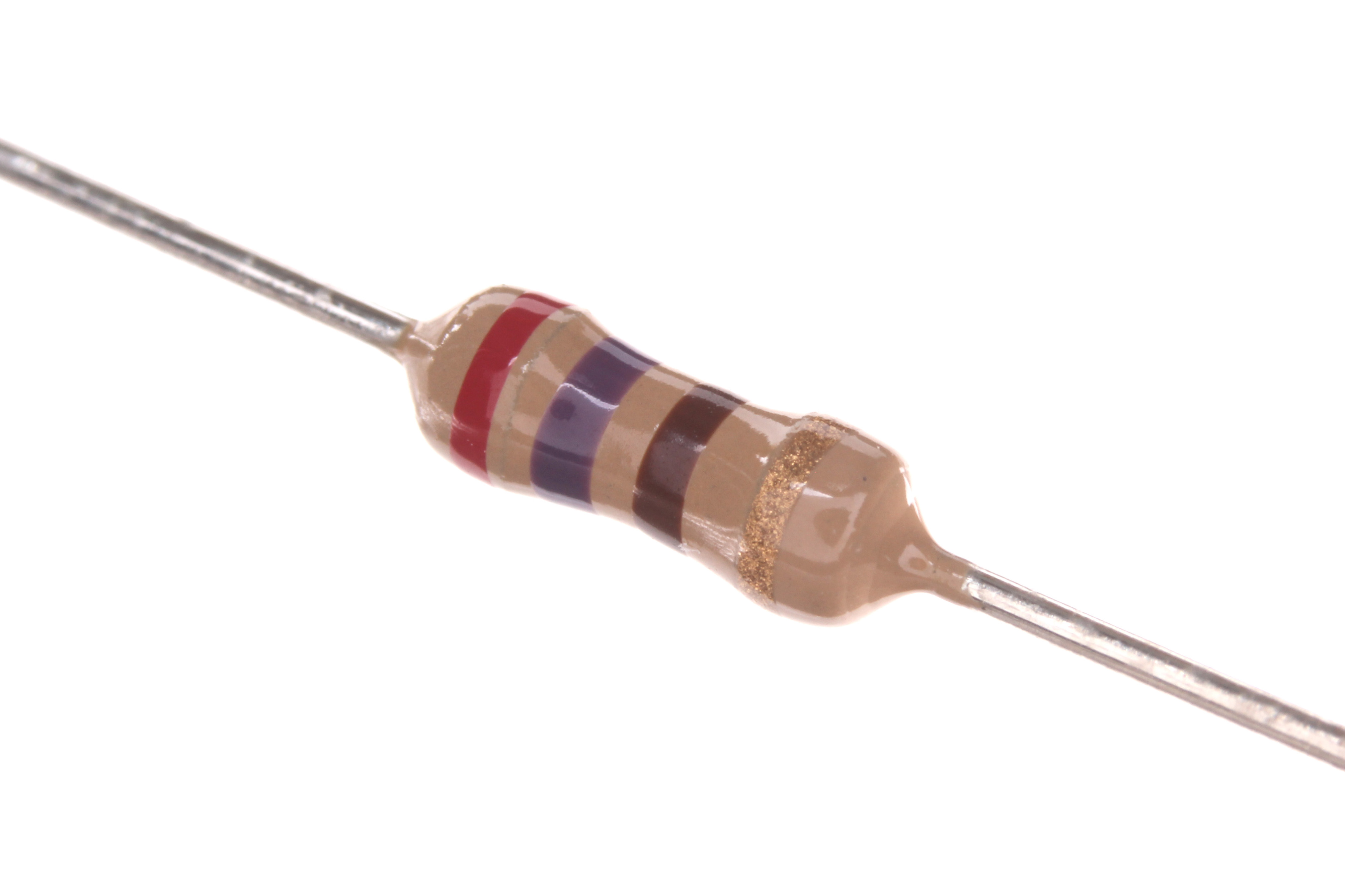
The macro photograph names the anatomy that recurs through the whole series. The body is the working part: inside it lies the actual resistive element — a spiral-cut film of carbon or metal, or a coil of resistance wire, or a printed track of oxide — chosen and shaped to hit the target resistance. The two leads are just tinned copper wire, there to carry current in and out and to be soldered into a board; in a surface-mount chip resistor they shrink to metallized end-caps, but the idea is the same. And the color bands are a printed code, a way of writing a value on a part too small to carry legible digits, one of the small elegant conventions of the trade that an entire later volume is devoted to decoding. For the moment it is enough to know that the stripes are not decoration: red-violet-brown-gold, on the part in the figure, is the number 270 ohms with a five-percent tolerance, written in a language a technician reads at a glance.
1.4 Power: Where the Energy Goes
Ohm’s law says how much current a voltage drives through a resistance. It says nothing, by itself, about the energy involved — and energy, in a resistor, is the whole point, because energy is heat and heat is what limits how hard a resistor can be worked. The governing quantity is power, the rate at which energy is delivered, measured in watts. For any electrical component the power it consumes is the voltage across it times the current through it:
P = V × I
For a resistor, Ohm’s law lets that be rewritten in two more forms that are often more convenient, because at the bench one usually knows the resistance and just one of the other two quantities. Substituting V = I × R gives power in terms of current and resistance; substituting I = V / R gives it in terms of voltage and resistance:
P = I² × R = V² / R = V × I
All three say the same thing. The first, P = I²R, is the one to reach for when the current is known — and note the square: double the current through a resistor and its heat production quadruples, which is why over-current is so quickly destructive. The second, P = V²/R, is the one to reach for when the voltage across the part is known. Every watt of that power becomes heat inside the resistor’s small body, and that heat has to go somewhere — into the surrounding air, down the leads into the circuit board, away by radiation — or the temperature climbs until something is damaged.
1.4.1 The Power Rating, and Why Two Resistors of “100 Ω” Are Not the Same
This is where a resistor’s second number enters, the one beginners tend to overlook: its power rating, the maximum power it can safely dissipate as heat without cooking itself. A resistor’s resistance and its power rating are two independent specifications. The resistance says how it divides voltage and current; the power rating says how much abuse it can take while doing so. This is exactly why a tiny 1/4-watt film resistor and a chunky finned 50-watt wirewound resistor can both be stamped “100 Ω” and both be perfectly correct. They will each present one hundred ohms to a circuit. But the little one can only turn a quarter of a watt into heat before it scorches, while the big one can shrug off two hundred times as much, because it has the mass and the surface area to shed the heat. The physical size of a resistor is very nearly a direct read-out of its power rating, not its resistance: a resistor is big because it must get rid of a lot of heat, never because it has a lot of ohms.
A worked example makes the stakes concrete. Suppose a designer needs a 100 Ω resistor to sit across a 12-volt supply. How much heat will it make? Using P = V²/R, that is 12² divided by 100, which is 144 / 100 = 1.44 watts. Hand that job to a common 1/4-watt resistor, rated for 0.25 W, and it is being asked to dissipate nearly six times what it can survive; it will overheat, discolor, drift in value, and eventually fail — possibly open-circuit, possibly in a puff of acrid smoke familiar to everyone who has ever built a circuit. The correct part here is at least a 2-watt resistor, and a cautious designer would fit a 3- or 5-watt part to run it cool, because a resistor run near its rating runs hot — often over 100 ΩC at the body — even when it is entirely within spec. The full art of choosing power ratings, including the derating that shrinks the allowable power as the ambient temperature rises, fills a later volume; the lesson to plant now is that every resistor carries two numbers, and ignoring the second one is how beginners let the smoke out.
1.5 Series and Parallel: Building the Value You Need
Standard resistors come only in a fixed ladder of preferred values — a subject in its own right, the E-series, treated later — so sooner or later a designer needs a resistance that no single part provides. The answer is to combine resistors, and there are two ways to wire two components together: end to end, or side by side. Each has a simple rule, and together they let any value be built from parts on hand.
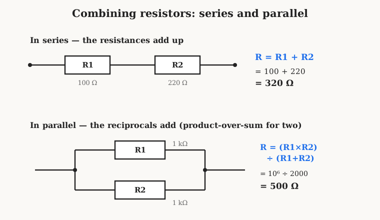
In series, resistors are strung end to end so the same current flows through each in turn, like a single stream of water passing through one constriction and then another. The constrictions simply add up, and so do the resistances:
R series = R1 + R2 + R3 + …
Two resistors of 100 Ω and 220 Ω in series make 320 Ω, and the total is always larger than the largest single resistor, because adding another constriction can only make the current’s journey harder. The intuition is worth holding: series means “and then,” obstacles in a row, opposition accumulating.
In parallel, resistors sit side by side between the same two points, so the current arriving at the junction can split and take either path, like a river dividing around an island. Offering the current a second route can only make the combined opposition less than either resistor alone — two doors are easier to get through than one. The rule is that the reciprocals add:
1 / R parallel = 1/R1 + 1/R2 + 1/R3 + …
Reciprocals are awkward to handle in the head, so for the common case of just two resistors in parallel there is a beloved shortcut, the product over sum:
R parallel = (R1 × R2) / (R1 + R2)
Two 1 kΩ resistors in parallel give (1000 × 1000) / (1000 + 1000) = 1 000 000 / 2000 = 500 Ω — exactly half, which is the special case worth memorizing: two equal resistors in parallel always give half the value, and n equal resistors in parallel give the value divided by n. Parallel means “or,” alternative routes, opposition easing. Between the two rules a designer with a drawer of ordinary values can hit almost any target: put a 1 kΩ in series with a 200 Ω for 1.2 kΩ, or two 1 kΩ in parallel for a precise 500 Ω, and awkward specifications dissolve into combinations of parts already on the shelf.
1.6 The Voltage Divider: the Resistor Circuit You Cannot Avoid
If one had to name the single most-used resistor circuit in all of electronics, it would be the voltage divider: two resistors in series across a voltage, with the output taken from the junction between them. It is so common, so foundational, that experienced engineers stop seeing it as a circuit at all and simply read it off by reflex. It does exactly what its name says — it takes an input voltage and delivers some fixed fraction of it — and it is the direct, physical embodiment of Ohm’s law in the “voltage drop” form met earlier.
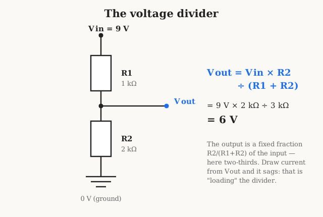
The reasoning behind the divider is short and worth following once, because once seen it is never forgotten. The two resistors are in series, so — as the last section established — the same current flows through both. That current is set by the total resistance: I = V in / (R1 + R2). The output voltage is simply the voltage that this current drops across the lower resistor, R2, and by Ohm’s law that drop is I × R2. Multiply it out and the current cancels, leaving the famous divider equation:
V out = V in × R2 / (R1 + R2)
The output is the input scaled by the fraction R2 / (R1 + R2) — the lower resistor’s share of the total. If the two resistors are equal, the output is exactly half the input. In the figure, 9 volts in with R1 = 1 kΩ and R2 = 2 kΩ puts two-thirds of the total across R2, giving 6 volts out. Change the ratio and the fraction changes; the absolute values barely matter, only their ratio sets the output, which is a liberating thing to realize.
1.6.1 Loading: the Divider’s One Catch
There is a catch, and it is the first thing to teach anyone who reaches for a divider carelessly. The clean equation above assumes that nothing draws current from the output — that the tap point feeds only an infinitely high-resistance load, a perfect voltmeter. Connect a real load that pulls current, and that load sits in parallel with R2, lowering the effective lower resistance and pulling the output voltage down below the ideal figure. This is called loading the divider, and it is why a voltage divider makes an excellent reference for a high-impedance input — the base of a transistor, the input of an op-amp, an analog-to-digital converter pin — but a poor power supply for anything that draws meaningful current. The rule of thumb is to make the divider “stiff” relative to its load: pick R1 and R2 small enough that the current flowing through the divider itself is much larger, ten times or more, than the current the load will steal, so the load’s theft is a rounding error. Make them too small, though, and the divider wastes power as heat around the clock. The tension between a stiff divider that ignores its load and an efficient divider that wastes little power is a real design trade-off, and recognizing it is a mark of the difference between someone who has read the equation and someone who has been burned by it.
Once the divider is understood, it is seen everywhere: setting the reference voltage for a comparator, biasing the gate or base of a transistor to its operating point, scaling a large voltage down into the range an ADC or a meter can read, providing the feedback fraction that tells a regulator or amplifier what output to hold. Learn the divider and a large fraction of every schematic suddenly parses.
1.7 Current Limiting: the Other Everyday Job
The divider’s mirror-image job is current limiting — using a resistor in series to hold current down to a safe or desired value. Where the divider exploits the voltage a resistor drops, the current limiter exploits the current a resistor allows, and it is the I = V / R form of Ohm’s law made flesh. The canonical example, met by everyone who has ever lit a light-emitting diode, is the humble LED series resistor.
An LED is a stubbornly non-ohmic device: below a certain forward voltage it barely conducts, and above it the current shoots up almost vertically for the tiniest further rise in voltage. Connect an LED straight across a supply and it will try to draw enormous current and destroy itself in an instant. It needs a partner that is ohmic to tame it, and that partner is a plain series resistor, which soaks up the difference between the supply voltage and the LED’s forward voltage and thereby fixes the current at a chosen, safe level.
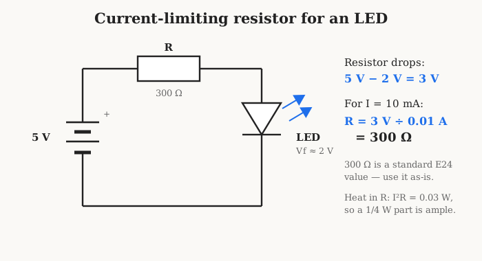
The design proceeds in three short steps, and it is the same recipe every time. First, find the voltage the resistor must drop: it is the supply voltage minus the LED’s forward voltage. A typical red LED holds about 2 volts across itself no matter what, so from a 5-volt supply the resistor must drop 5 − 2 = 3 volts. Second, decide the current wanted — a comfortable, bright, safe 10 milliamps for an indicator LED, which is 0.010 amps. Third, apply R = V / I: 3 volts divided by 0.010 amps is 300 Ω. That happens to be a standard E24 value, so the designer fits a 300 Ω resistor and moves on; had the arithmetic landed on an oddball number, one would round up to the next standard value, trading a hair of brightness for a part that actually exists. A quick check on power finishes the job: the resistor dissipates I²R = 0.010² × 300 = 0.03 watts, a trivial thirty milliwatts, so the smallest common 1/4-watt resistor is entirely comfortable. That three-step ritual — find the voltage to drop, choose the current, divide for the resistance, then check the power — is one of the most-repeated calculations in all of electronics, and it is nothing more than Ohm’s law and the power law applied in sequence.
1.8 The Schematic Symbols
A resistor has to be drawn as well as built, and here the world is split by an old convention that anyone reading schematics from more than one country will meet. There are two standard symbols for a fixed resistor, and they mean exactly the same thing.
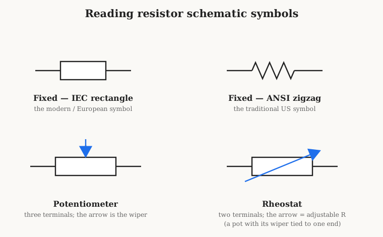
The IEC rectangle — a plain, empty box sitting in the wire — is the symbol laid down by the International Electrotechnical Commission and used across Europe and in modern international practice. The ANSI zigzag — the familiar jagged sawtooth line, like a row of sharp mountain peaks — is the older American symbol, still ubiquitous in United States schematics, hobbyist literature, and countless textbooks. A reader will meet both, sometimes on the same page, and should treat them as perfect synonyms: box or zigzag, it is a resistor either way. Neither symbol, on its own, says anything about the resistance value or the power rating; those are written alongside as text, such as “R7 4.7 kΩ.”
The figure also gives a first glimpse of the variable resistors, which fill a later volume of their own. A potentiometer — a “pot” — is drawn as a resistor with a third terminal, an arrow pressing in against the body; that arrow represents the wiper, a sliding or rotating contact that taps off the resistance at an adjustable point along its length. A pot is, in effect, a voltage divider whose ratio the user can turn — which is exactly what the volume-control knob on an audio amplifier is doing. A rheostat is the two-terminal cousin, drawn as a resistor with a diagonal arrow struck through it to mean “this resistance is adjustable”; it is used to vary a current directly rather than to divide a voltage, and it is really just a potentiometer with its wiper tied to one end. The single unifying convention to carry away is that an arrow through or against a component means it is adjustable — a rule that holds for resistors, capacitors, and inductors alike.
1.9 Why Resistors Are Everywhere — and the Road Ahead
Step back and the reason resistors outnumber every other component becomes obvious. Nearly every task in a circuit comes down to setting a current, dropping or dividing a voltage, or turning a little energy into heat on purpose — and those are precisely the three things a resistor does. A transistor needs its bias set: a resistor or two does it. A logic input must be held at a definite level when nothing else drives it: a pull-up or pull-down resistor holds it. An LED, a laser diode, a sensor needs its current bounded: a series resistor bounds it. A signal on a fast cable must not bounce back off the far end: a termination resistor absorbs it. An amplifier’s gain, a filter’s corner, a timer’s interval, an oscillator’s frequency — all are set by resistors working with their storing siblings. The resistor is the connective tissue of electronics, the part that makes every other part sit at the right operating point. That is why a board carries hundreds of them and why mastering the resistor is the natural first step into the whole subject.
This volume has laid the foundation: what a resistor is and how it differs from its storing siblings, Ohm’s law in its three forms, the ohm and the vast range of real values, power and the all-important power rating, series and parallel combination, the voltage divider, current limiting, and the symbols on the page. The thirteen volumes that follow build outward from here, each taking one facet down to the depth a working engineer needs:
- Volume 2 — Resistance itself: resistivity and conductivity, why some materials resist and others conduct, how resistance changes with temperature, and the notion of sheet resistance — the physics beneath the part.
- Volume 3 — The real resistor: tolerance, temperature coefficient, voltage coefficient, thermal and excess noise, the parasitic inductance and capacitance that spoil the ideal at high frequency, and drift over time — the equivalent circuit of an honest resistor.
- Volume 4 — A short history: from Ohm and the rheostat and the Wheatstone bridge, through the carbon-composition and wirewound eras, to the film revolution and the surface-mount chip.
- Volume 5 — How resistors are made: carbon-film, metal-film, thick- and thin-film, and wirewound manufacture; laser and abrasive trimming; and the axial, chip, and MELF packages.
- Volume 6 — Reading resistors: the four-, five-, and six-band color code, the E-series and why its values are what they are, the EIA-96 and SMD codes, and the letter notations — the single most-searched resistor topic, given its own authoritative treatment.
- Volume 7 — Fixed types I: carbon composition, carbon film, metal film, and metal-oxide film, compared on tolerance, tempco, noise, and cost.
- Volume 8 — Fixed types II: wirewound, bulk metal foil, and thick- and thin-film chip resistors — the power and precision extremes of the family.
- Volume 9 — Power and derating: the power rating in full, derating curves, temperature rise, pulse and surge energy, safe operating area, and heat-sinking.
- Volume 10 — Networks, arrays, and the potentiometer: resistor networks and arrays, potentiometers and their tapers, rheostats, trimmers, multiturn parts, and digital pots.
- Volume 11 — Specialty and sensing resistors: current-sense shunts and four-terminal Kelvin connection, high-voltage and high-power types, fusible resistors, and the sensing cousins — thermistors, varistors, photoresistors, and strain gauges.
- Volume 12 — Where resistors are used and how to choose: pull-ups and pull-downs, biasing, current limiting, dividers, terminations, gain-setting, and snubbers, gathered into a selection guide.
- Volume 13 — Measuring and testing resistors: the ohmmeter, four-wire Kelvin measurement, the Wheatstone and Kelvin bridges, and the special arts of measuring very high and very low resistances.
- Volume 14 — Reference: a glossary, the color-code and SMD-code tables, the E-series tables, standard values, letter codes, and a package chart — the bench companion to the whole set.
With Ohm’s law and the power law in hand, the reader already holds the two keys that unlock every one of those volumes. Everything ahead is an elaboration of the bargain struck on this first page: control, purchased with heat.
Comments (0)