Resistors · Volume 2
Resistance Itself: Resistivity, Materials, and Temperature
2.1 From the part back to the material
The foundational volume treated a resistor as a number: a component with a value in ohms, a place in a divider, a certain amount of heat to shed. That is exactly the right altitude for circuit design, but it leaves a question unanswered. Where does the number come from? Two resistors can both read 1 kΩ on a meter and be built of utterly different stuff — a fired dab of carbon-and-clay, a whisker of coiled nichrome, a purple film of nickel-chromium sputtered a few atoms thick onto a ceramic chip. The ohm is a property of the finished object; but the object is only a way of packaging something more fundamental. Resistance is not really a property of a part. It is a property of a material, shaped by geometry.
This volume steps back from the component to the substance it is made of, in the same way the Coils dive steps back from the winding to the magnetic properties of the core. The goal is to answer three physical questions plainly enough that a layman can follow and precisely enough that an engineer gets a bench answer: what makes one material resist the flow of current more than another; why that resistance changes when the material gets hot; and why the same material, drawn out long and thin, resists more than when it is short and fat. Get those three, and every fact in the rest of the dive — why a precision resistor is made of a copper-manganese-nickel alloy rather than pure copper, why a carbon resistor’s value creeps the wrong way with temperature, why a film resistor is trimmed by scratching a spiral into it — falls into place as a consequence rather than a rule to memorise.
2.2 Resistivity and conductivity: the material’s own number
The property that belongs to the material, stripped of any particular shape, is called resistivity, written with the Greek letter ρ (rho). Its unit is the ohm-metre (Ω·m). Loosely, resistivity answers the question: if this material were formed into a standard cube — one metre on a side — and current were pushed straight through from one face to the opposite face, how many ohms would it show? Silver’s resistivity is about 1.59 × 10⁻⁸ Ω·m; a metre cube of silver conducts almost perfectly. Ordinary window glass is up near 10¹² Ω·m, a hundred billion trillion times higher; a metre cube of glass conducts essentially nothing. Between those two extremes lies every conductor, resistor, and insulator in existence.
Resistivity has a mirror image. Its reciprocal is conductivity, written σ (sigma):
σ = 1 / ρ
Conductivity measures the same physics from the opposite side — how easily current flows rather than how much the material fights it. Its unit is the siemens per metre (S/m). A material with high conductivity has low resistivity, and vice versa; they are two names for one fact. Physicists and materials scientists tend to speak of conductivity because it rises with the thing they care about (free electrons); resistor engineers tend to speak of resistivity because it rises with the thing they care about (opposition to current). Both appear throughout this dive, and it is worth being fluent in switching between them: a good conductor has low ρ and high σ; a good resistor material has moderate, and above all stable, ρ.
2.3 The geometry law: R = ρL / A
Resistivity is the material’s contribution; geometry supplies the rest. The resistance of a uniform piece of material is given by one of the most useful equations in all of electronics:
R = ρ · L / A
where L is the length of the path the current takes and A is the cross-sectional area it flows through. Read it as a sentence and it is pure common sense. Resistance rises with length: the longer the road, the more collisions the charge suffers on the way, so a long wire resists more than a short one of the same stuff. Resistance falls with cross-sectional area: a fat conductor is many thin conductors side by side, and putting resistors in parallel lowers the total, so a thick wire resists less than a thin one. And it scales with the material’s own ρ: swap copper for nichrome and the resistance jumps by whatever factor their resistivities differ.
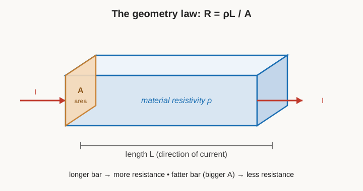
The picture makes the three levers visible at once: the material fills the bar (ρ), the current travels its length (L), and it squeezes through the shaded end face (A). Everything a resistor manufacturer does — choosing an alloy, drawing it to a gauge, cutting it to a length, or laying down a film of a certain thickness — is a way of setting one of these three quantities.
2.3.1 A worked example: a length of nichrome heater wire
Numbers make the law concrete. Consider a designer building a small heating element and reaching for 26 AWG nichrome wire — a common choice, about 0.405 mm in diameter. Nichrome’s resistivity is roughly 1.10 × 10⁻⁶ Ω·m (the exact figure depends on the grade; the 80/20 nickel-chromium alloy sits near 1.10, and higher-iron grades run a little above). First the cross-sectional area of a round wire, A = πd²/4:
A = π × (0.000405 m)² / 4 ≈ 1.29 × 10⁻⁷ m²
Then the resistance of a metre of it, R = ρL/A:
R = (1.10 × 10⁻⁶ Ω·m × 1 m) / (1.29 × 10⁻⁷ m²) ≈ 8.5 Ω per metre
So if the element needs to be, say, 48 Ω to draw the right power from the supply, the designer needs about 48 / 8.5 ≈ 5.6 metres of this wire, which is why heating elements are coiled — that much wire has to be packed into a small space. Now run the same wire in copper for comparison. Copper’s resistivity is 1.68 × 10⁻⁸ Ω·m, about 65 times lower, so a metre of the identical-gauge copper wire is only about 0.13 Ω. This is the whole point of a resistance material in a single comparison: to get a useful number of ohms out of a manageable length of wire, the designer needs a material that resists tens of times harder than the copper used to carry current to it. Copper is for wires; nichrome is for resistance.
2.4 What makes a good conductor versus a good resistor
The instinct is that a good resistor material should have very high resistivity. It should not. The resistivity ladder below spans twenty-six orders of magnitude, and the useful resistor materials sit in a surprisingly narrow band well away from either end.
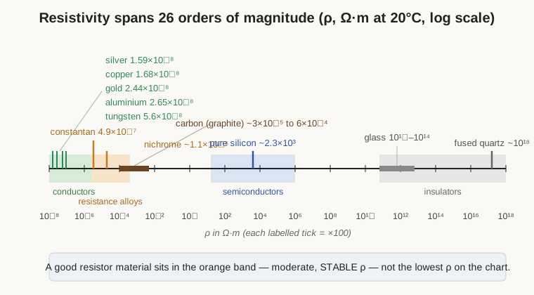
At the far left are the elemental metals — silver, copper, gold, aluminium, tungsten — clustered within a factor of four of one another, all near 10⁻⁸ Ω·m. These are the conductors. Their job is to carry current from one place to another while adding as little resistance, and dropping as little voltage, as possible. Silver is the best of them but too expensive for wire; copper is very nearly as good and cheap enough to build a civilisation on; aluminium trades some conductivity for a third of the weight, which is why overhead power lines are aluminium; gold resists tarnish, which is why it plates connector contacts; tungsten’s high melting point earns it the incandescent lamp filament despite a resistivity several times copper’s.
At the far right are the insulators — glass, ceramics, most plastics, fused quartz — up beyond 10¹⁰ and often far higher. Their job is the opposite: to not conduct, to hold two conductors apart, to be the dielectric of a capacitor or the body of a resistor. Between these extremes, near 10² to 10³ Ω·m, sit the semiconductors like silicon, whose resistivity is neither fixed nor a nuisance but a control knob — the entire foundation of the transistor, but a story for another dive.
The resistor material lives in none of these places. It lives in the modest band from roughly 10⁻⁷ to 10⁻⁵ Ω·m — an order or two above the good conductors. This is the home of the resistance alloys: constantan at about 4.9 × 10⁻⁷ Ω·m, nichrome at around 1.0 to 1.5 × 10⁻⁶, manganin a little below constantan. Carbon sits a decade or so higher still, anisotropic and spread across a wide range (graphite runs from about 3 × 10⁻⁵ Ω·m along its planes to far higher across them, so it is always quoted as a range). Why this middle band? Because a resistor’s job is to produce a specific, predictable number of ohms out of a manufacturable amount of material. Too low a resistivity and the part must be absurdly long and thin to reach a useful value — a 10 kΩ copper resistor would be kilometres of hair-fine wire. Too high a resistivity and the value becomes hypersensitive to tiny variations in geometry, contamination, and temperature, impossible to hold to 1%. The sweet spot is moderate resistivity. But moderate resistivity is not enough on its own: the ideal resistor material is one whose ρ barely moves — with temperature, with time, with voltage. Stability, not magnitude, is what separates a precision resistance alloy from an ordinary conductor. The rest of this volume is about where that stability comes from and why it is so hard to get.
Two cautions travel with any resistivity table. First, every value is quoted at a stated reference temperature — almost always 20°C, occasionally 25°C — precisely because, as the next section shows, resistivity moves with temperature; a resistivity given without a temperature is meaningless, and comparing two materials means comparing them at the same one. Second, some materials have no single resistivity because they are anisotropic — their ρ depends on direction. Graphite is the standout: current flows easily along its sheets of carbon atoms but poorly across the stack of sheets, so its resistivity spans more than an order of magnitude depending on orientation, which is why the table quotes it as a range rather than a point. Ordinary polycrystalline metals average out to a single figure because their grains point every which way, but the lesson holds — a resistivity number is a summary of a measurement made under stated conditions, not an immutable constant of the universe.
The table gathers the representative figures, all at about 20°C:
Table 1 — The table gathers the representative figures, all at about 20°C
| Material | Resistivity ρ (Ω·m) | Role |
|---|---|---|
| Silver | 1.59 × 10⁻⁸ | best metallic conductor |
| Copper | 1.68 × 10⁻⁸ | the workhorse conductor |
| Gold | 2.44 × 10⁻⁸ | corrosion-proof contacts |
| Aluminium | 2.65 × 10⁻⁸ | light-weight conductor |
| Tungsten | 5.6 × 10⁻⁸ | lamp filaments |
| Constantan (Cu55/Ni45) | ~4.9 × 10⁻⁷ | near-zero-tempco alloy |
| Manganin (Cu/Mn/Ni) | ~4.8 × 10⁻⁷ | precision shunts, standards |
| Nichrome (Ni80/Cr20) | ~1.0–1.5 × 10⁻⁶ | heaters, wirewound resistors |
| Carbon (graphite) | ~3 × 10⁻⁵ to 6 × 10⁻⁴ | carbon-composition & film |
| Pure silicon | ~2.3 × 10³ | semiconductor |
| Glass | ~10¹⁰–10¹⁴ | insulator |
| Fused quartz | ~10¹⁸ | best common insulator |
2.5 Why materials resist at all
Resistivity is a measured fact, but it has a cause, and the cause is worth understanding because it explains everything that follows about temperature and stability. The intuitive model — good enough to reason with, and close enough to the truth for engineering — is the one Paul Drude proposed in 1900, only a few years after the electron was discovered.
Picture a metal as a rigid lattice of positive ions, the atoms having each given up an outer electron. Those liberated electrons are not bound to any particular atom; they wander freely through the whole crystal like a gas, which is why they are called the “free electron sea.” With no applied voltage they zip around at high speed but in random directions, so no net current flows — as many cross any line one way as the other. Apply a voltage across the metal and you establish an electric field inside it, and that field pushes on every free electron with a steady force, nudging them all, on average, in one direction.
If nothing stood in their way, the electrons would simply accelerate faster and faster and the current would climb without limit — the metal would have no resistance at all. Something does stand in their way. As an electron drifts along, it repeatedly collides — scatters — off the lattice. Every collision randomises its direction and robs it of the sideways momentum the field had been building up, and then the field starts pushing it along again from scratch. The electron therefore does not accelerate freely; it lurches forward in a series of short accelerations punctuated by collisions, and settles into a slow, steady average called the drift velocity.
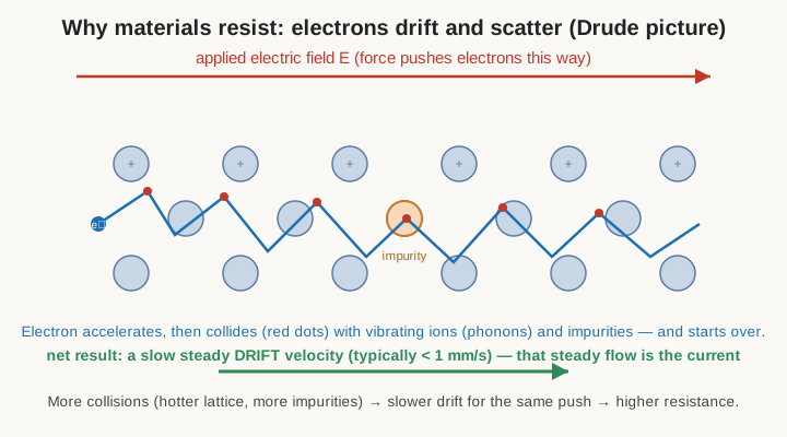
Two facts about that drift surprise people. First, it is extraordinarily slow — a fraction of a millimetre per second in a typical wire, far slower than a walking pace, even though the signal (the field itself) propagates near the speed of light and the individual electrons’ random speeds are enormous. The current is large only because there are so many electrons drifting at once. Second, this steady drift is the resistance. Resistance is not some frictional force added on top; it is simply the statistical result of countless collisions preventing the electron sea from accelerating without limit. Ohm’s law — current proportional to voltage — falls straight out of this model, because a stronger field produces a proportionally faster drift.
It is worth pinning down just how slow the drift is, because the number is genuinely counter-intuitive. In a copper wire of ordinary gauge carrying a few amps, the drift velocity works out to well under a tenth of a millimetre per second — an electron entering one end of a metre of wire would take hours to physically reach the other end. Yet a lamp lights the instant the switch closes. The resolution is that the wire is already packed full of free electrons everywhere along its length; closing the switch establishes the field almost instantly all down the wire, and every electron begins to drift at once, like a pipe already full of water pushing a drop out the far end the moment the tap opens. What travels near light-speed is the field and the resulting push; the electrons themselves merely shuffle. This same fact — an enormous number of charges each moving slowly — is why a thin wire can carry a large current, and why the current a material can pass is captured by the microscopic form of Ohm’s law, J = σE: the current density J is the material’s conductivity σ times the field E. It is the same law as V = IR, written for a point inside the material rather than for the whole part, and it is the version that connects directly to the resistivity ladder.
What does the electron collide with? Two things, and the distinction is the key to the whole temperature story. It scatters off lattice vibrations — the ions are not frozen in place but jiggle with thermal energy, and the quantised packets of that vibration are called phonons — and it scatters off imperfections: impurity atoms of the wrong element, vacancies where an atom is missing, grain boundaries, dislocations, anything that breaks the perfect regularity of the crystal. A perfectly pure, perfectly cold crystal would let electrons glide through almost unimpeded; it is the vibrations and the flaws that produce resistance. This is captured in Matthiessen’s rule, which says the two contributions simply add: the total resistivity is the impurity part (roughly constant with temperature) plus the phonon part (which grows as the lattice heats up). That second term is where temperature enters.
2.6 The temperature story: PTC metals versus NTC carbon
Now the payoff. Because resistance comes from scattering, anything that changes how often electrons scatter changes the resistance — and temperature changes it powerfully, but in opposite directions for metals and for carbon or semiconductors.
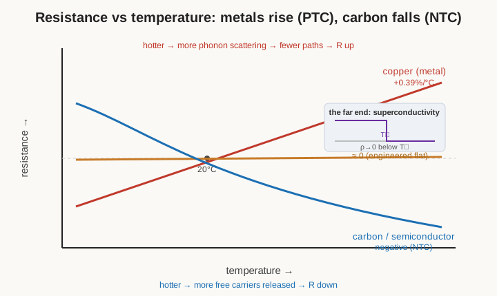
In a metal, the number of free electrons is fixed; every atom donated its one or two and there are no more to be had. Heating the metal does not create more carriers. What it does is make the lattice ions jiggle harder — more thermal vibration, more phonons — so a drifting electron slams into the agitated lattice more often. More collisions, shorter time between them, slower drift for the same push: the resistance rises as the metal gets hotter. This is a positive temperature coefficient, or PTC, and it is a universal property of ordinary metals. For copper it runs about +0.39% per °C near room temperature — meaning a copper winding that measures 100 Ω cold will read closer to 139 Ω after a 100 °C rise. This is not a defect; it is the physics, and it is exploited deliberately: a copper or platinum resistance thermometer measures temperature precisely because its resistance climbs so reliably with it.
Carbon and semiconductors do the reverse. In these materials the free carriers are not all liberated to begin with; many electrons are still bound, and it takes energy to shake them loose into conduction. Heating the material supplies exactly that energy, freeing more carriers. That effect — more carriers available to carry current — swamps the increased scattering, so the resistance falls as the material gets hotter. This is a negative temperature coefficient, or NTC. Carbon-composition resistors show it (part of why they are no longer the precision choice), and it is the entire operating principle of the NTC thermistor, a component this dive returns to in the specialty-resistor volume, where the falling-resistance-with-heat behaviour is the sensor’s output rather than an annoyance.
2.6.1 The resistance-alloy trick: engineering the tempco to zero
If a metal’s resistance rises with heat and a semiconductor’s falls, is there a material whose resistance barely changes at all? There is — but nature does not hand it out; metallurgists build it. Constantan (roughly 55% copper, 45% nickel) and manganin (about 84% copper, 12% manganese, 4% nickel) are alloys formulated so that their temperature coefficient is very nearly zero over a useful range around room temperature — a few parts per million per °C, a thousand times flatter than copper. Constantan’s very name advertises the property: its resistance stays constant.
How is that possible when both are mostly copper, and copper has a large positive tempco? The trick is a controlled balancing act. Alloying copper heavily with nickel or manganese does two things at once. It raises the base resistivity by adding a large, temperature-independent impurity-scattering term (the Matthiessen impurity contribution), which by itself dilutes the fractional effect of temperature. And in the right proportions the alloy’s electronic structure produces small competing shifts — one part of the effect rising with temperature, another falling — that can be tuned to cancel near the design temperature. The result is a material with moderate resistivity (ideal for resistors, as the ladder showed) and a resistance that hardly drifts as it warms. Manganin and the modern nickel-chromium precision alloy Evanohm are the reason a laboratory standard resistor or a current-sense shunt can hold its value to parts per million while the current through it heats it up. Volume 3 quantifies this drift as the temperature coefficient of resistance, measured in ppm/°C, and it is the single most important spec separating a precision resistor from a commodity one. The physics of why some materials can be made so flat is the story told here.
2.7 Sheet resistance: ohms per square
There is one more idea from this material-and-geometry level that the film-resistor volumes depend on completely, and it is worth setting up carefully because it looks strange the first time: sheet resistance, quoted in the odd-looking unit of ohms “per square,” written Ω/□.
Return to R = ρL/A, but now the material is not a wire — it is a thin, flat film, laid down on a substrate to a certain thickness t. For a film, the cross-sectional area that current flows through is the film’s width W times its thickness t, so A = W·t. Substitute that into the geometry law and group the terms deliberately:
R = ρL / A = ρL / (W·t) = (ρ / t) × (L / W)
Look at what happened. The two material-and-thickness quantities collapsed into a single number, ρ/t, and everything to do with the shape collapsed into the ratio L/W. That first lumped quantity is the sheet resistance:
R_s = ρ / t
and the resistance of any patch of that film is simply:
R = R_s × (L / W)
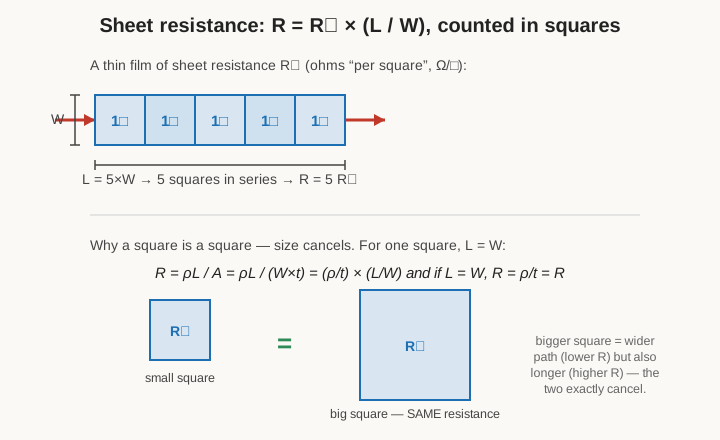
The ratio L/W is dimensionless — it is the number of squares of film you could lay end to end along the current’s path. Hence the name. If a strip is five times as long as it is wide, it is “five squares,” and its resistance is 5·R_s regardless of whether those squares are a millimetre or a micron on a side. That is the part that startles people: a square of any size has the same resistance. The reason is that R_s already has L/W baked out of it. Make the square bigger and you widen the current path, which lowers resistance in proportion to the extra width — but you have also lengthened the path by exactly the same factor, which raises resistance in proportion. The two effects are always equal for a square, so they cancel exactly, and every square of a given film, large or small, shows the identical R_s. The unit “ohms per square” is dimensionally just ohms; the “per square” is a reminder that you multiply by the count of squares, not by any length.
A worked case makes the leverage obvious. Suppose a maker deposits a film with a sheet resistance of 100 Ω/□. To build a 10 kΩ resistor from it, the film only has to be shaped into a path 100 squares long: R = 100 Ω/□ × 100 squares = 10,000 Ω. Those hundred squares might be a serpentine 2 mm long and 20 µm wide (100 squares of 20 µm each), fitting comfortably on a 0603 chip. Want 1 kΩ from the identical film? Ten squares. Want 47 Ω? Just under half a square — a short, fat patch. The absolute dimensions are set by the package and the power rating; the value is set purely by the square count, which is why one deposition recipe can serve a whole decade of resistance values and why datasheets for film materials quote a menu of available sheet resistances (10, 50, 100, 1000 Ω/□ and so on) rather than fixed resistances.
For a manufacturer this is a gift. A resistor maker deposits a film of, say, 100 Ω/□ metal-nitride onto a ceramic chip, and then needs only to arrange the right number of squares between the two end contacts to hit any target value. A short, wide patch of a fraction of a square gives a few ohms; a long, narrow serpentine of a thousand squares gives 100 kΩ from the very same film. And because the value depends only on a geometric ratio, it can be adjusted after the fact by cutting away film — scratching a spiral or a plunge cut that forces the current to snake through more, narrower squares, raising the resistance precisely to the target. This is exactly how film resistors are trimmed, and it is the physical basis of the laser and abrasive trimming described in the manufacturing volume. Sheet resistance is the concept that connects the material physics of this volume to the making of every film and chip resistor in Volumes 5 through 8.
2.8 Resistance materials in practice
With the physics in place, the cast of real resistance materials each make sense as a particular answer to “moderate, stable resistivity, made cheaply enough for the job.” A crisp tour, with pointers to where each is treated in depth later:
Carbon. The oldest resistance material and still the cheapest. As a molded mix of graphite and a ceramic or resin binder it makes the carbon-composition resistor; as a thin pyrolytic coat cracked onto a ceramic rod it makes the carbon-film resistor. Carbon’s resistivity is high and easily adjusted by the graphite-to-binder ratio, and it survives large energy pulses well, but it has a negative tempco, poor tolerance, and more electrical noise than metals — so it has been displaced from precision work but survives where surge-handling or low cost rules (Volume 7).
Nichrome (nickel-chromium, typically 80/20). The default resistance wire. It combines a resistivity around 1.1 × 10⁻⁶ Ω·m — high enough to make a useful element from a manageable length — with excellent resistance to oxidation even glowing red-hot, because the chromium forms a protective oxide skin. That is why it is the wire in toasters, hair dryers, kilns, and the element of countless heaters, and also why it is wound onto ceramic to make power wirewound resistors (Volume 8). Its tempco is far lower than pure metals but not zero.
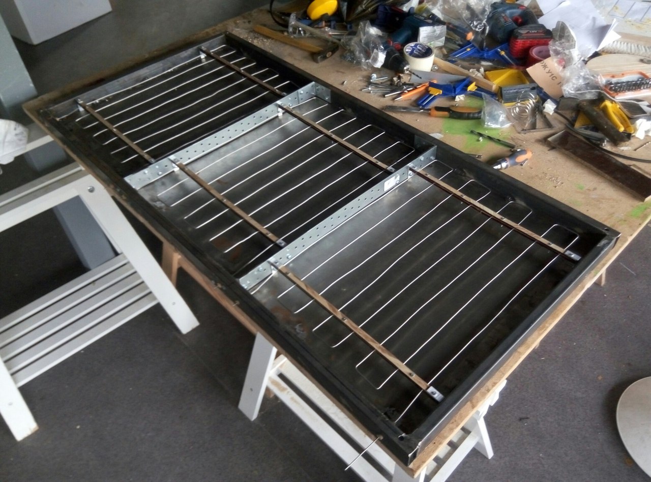
Constantan (copper-nickel, ~55/45). The classic near-zero-tempco alloy. Its resistance barely moves with temperature, which makes it ideal for precision wirewound resistors and, famously, for strain gauges and thermocouples. Its one quirk — a large thermoelectric voltage against copper — is precisely what makes it a good thermocouple leg but a nuisance in low-level precision resistors, where manganin is preferred.
Manganin and Evanohm. Manganin (copper-manganese-nickel) has an even flatter tempco than constantan near room temperature and a small thermal EMF against copper, which is why it is the material of laboratory standard resistors and precision current-sense shunts — a manganin shunt can carry heavy current, heat up, and still report the current faithfully because its resistance holds. Evanohm and related nickel-chromium-aluminium-copper alloys push this further, combining very high resistivity with a tempco tunable to a handful of ppm/°C, and are the backbone of the finest wirewound and bulk-metal-foil precision resistors (Volume 8).
Metal and metal-oxide films. Sputtered or evaporated films of nickel-chromium or tantalum nitride give the metal-film resistor its excellent tolerance, low noise, and low tempco; a fired film of tin oxide (SnO₂) gives the metal-oxide resistor a higher power and temperature capability than carbon film. These thin films are where the sheet-resistance idea earns its keep — the value is set by depositing the right R_s and trimming the right number of squares.
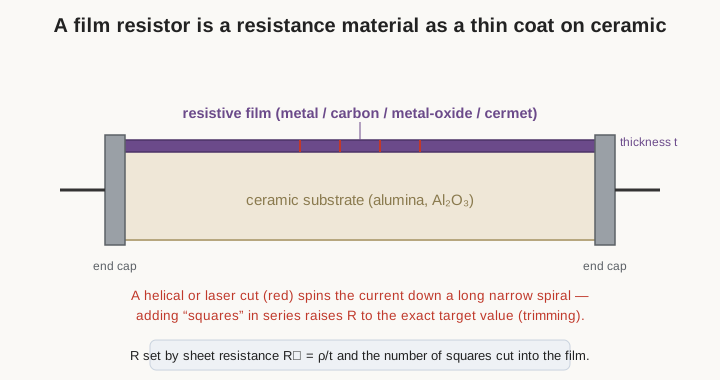
Cermet and thick-film (RuO₂). A cermet is a fired blend of ceramic and metal — the name is a portmanteau of the two. The dominant thick-film resistor material is ruthenium oxide (RuO₂) mixed into a glass frit, screen-printed as a paste and fired onto ceramic. It gives a wide range of sheet resistances, good stability, and low cost at high volume, which is why the overwhelming majority of the tiny black chip resistors on any modern circuit board are RuO₂ thick-film (Volume 8). Cermet is also the resistive track in most trimmer potentiometers (Volume 10).
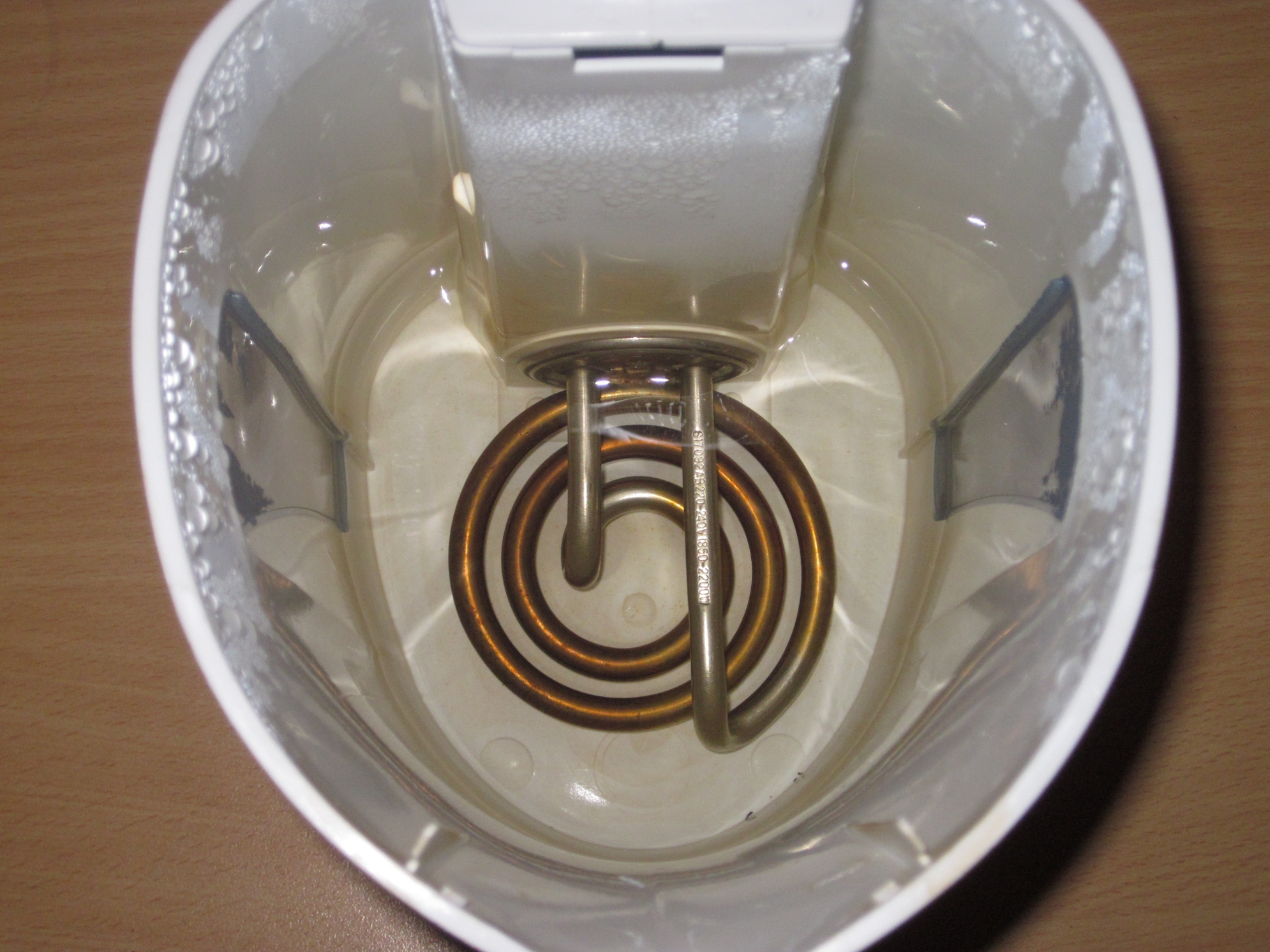
The photograph below shows one of these materials doing the most literal possible job — a resistance-wire element inside a domestic kettle, turning the material’s resistivity directly into heat by the I²R relationship of Volume 1.
2.9 Honorable mention: the far end of the scale
The resistivity ladder had a left-hand edge — the best ordinary conductors near 10⁻⁸ Ω·m — but it is not truly the end. Below a certain critical temperature T_c, some materials undergo a phase change in which their resistivity does not merely fall but drops abruptly to exactly zero: superconductivity. A current started in a superconducting loop will circulate indefinitely with no measurable decay, because there is no resistance to dissipate it. The Drude picture, extended, hints at why this is so strange: in a normal metal, scattering can never be fully switched off, so ρ can approach but never reach zero. Superconductivity is a genuinely different state, in which electrons pair up and move through the lattice collectively, immune to the scattering that produces ordinary resistance. It is not a resistor material — the whole point is that it is not resistive — and its temperatures (from a few kelvin for classic metals to ~90 K for the ceramic cuprates) keep it out of everyday components. But it belongs on the map as the ultimate answer to “how low can resistivity go,” bracketing the enormous span this volume has crossed: from zero, through the everyday conductors, up past the modest and carefully tuned resistance alloys where all the resistor engineering lives, and on to the near-perfect insulators twenty-six decades away.
That span, and the reason the useful resistor materials cluster in the middle of it, is the ground the rest of the dive builds on. The next volume takes the single number “resistance” apart into all the ways a real resistor deviates from its ideal — tolerance, the temperature coefficient this volume traced to its physical root, voltage coefficient, noise, and the parasitic inductance and capacitance that make a resistor stop behaving like one at high frequency.
Comments (0)