Resistors · Volume 4
A Short History: From Ohm to the Surface-Mount Chip
4.1 The oldest idea in electronics
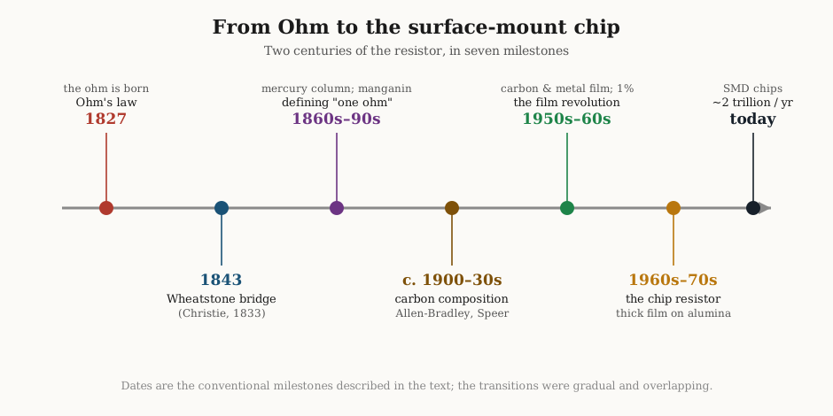
Of the three fundamental passive components, the resistor is the one whose behaviour was understood first and whose modern form is the most radically transformed. A capacitor from 1746 — the Leyden jar — is recognisably the ancestor of the film capacitor on a bench today; an inductor is still, at bottom, a coil of wire wound the way Faraday would have wound it. The resistor is different. The physical law that governs it was written down in 1827, before anyone had a practical use for a deliberately resistive part, and the component itself did not settle into a commercial article until the vacuum-tube age demanded it by the million. In the two centuries between, the resistor shrank from a metre-long column of mercury kept in a temperature-controlled bath to a speck of screen-printed metal-oxide the size of a grain of sand, produced today at a rate that beggars the imagination — well over two trillion of the smallest ones every year.
This volume tells that story as a story: how a schoolteacher’s obscure and ridiculed pamphlet became the most-quoted law in electrical engineering; how a borrowed circuit named after the wrong man became the precision instrument of the nineteenth century; how the world’s metrologists spent thirty years arguing about how long a tube of mercury had to be; and how the humble carbon rod gave way to film, and film to the surface-mount chip that anonymous automated lines now place onto circuit boards faster than the eye can follow. The later volumes of this dive explain what each of these parts is and how to use it. This one explains how they came to exist, and why the resistor is at once the oldest idea in electronics and still, by unit count, the most-manufactured object the industry makes.
4.2 Georg Ohm and the birth of “resistance”
Before 1827 there was no clean concept of resistance at all. Investigators of the galvanic circuit — the new world opened up by Volta’s pile in 1800 — knew that some arrangements of wire and battery gave a livelier spark or a stronger deflection of a compass needle than others, and they had vague, competing notions about why. They spoke of the “tension” of a pile and the “quantity” of its current in ways that muddled what we would now separate into voltage, current, and resistance. Length of wire clearly mattered; so did its thickness and its material; but nobody had reduced these observations to a rule that could be written as an equation and trusted to predict a number.
Into this confusion stepped Georg Simon Ohm, born in 1789 in Erlangen, Bavaria, the son of a self-taught master locksmith who had drilled his boys hard in mathematics and physics. Ohm was, in 1825, a schoolmaster teaching mathematics at the Jesuit gymnasium in Cologne — a provincial post far from the academies of Berlin — and he was ambitious to escape it. He had access to a good physics cabinet and he set about, in his spare hours, to measure the galvanic circuit with a rigour nobody had yet applied to it.
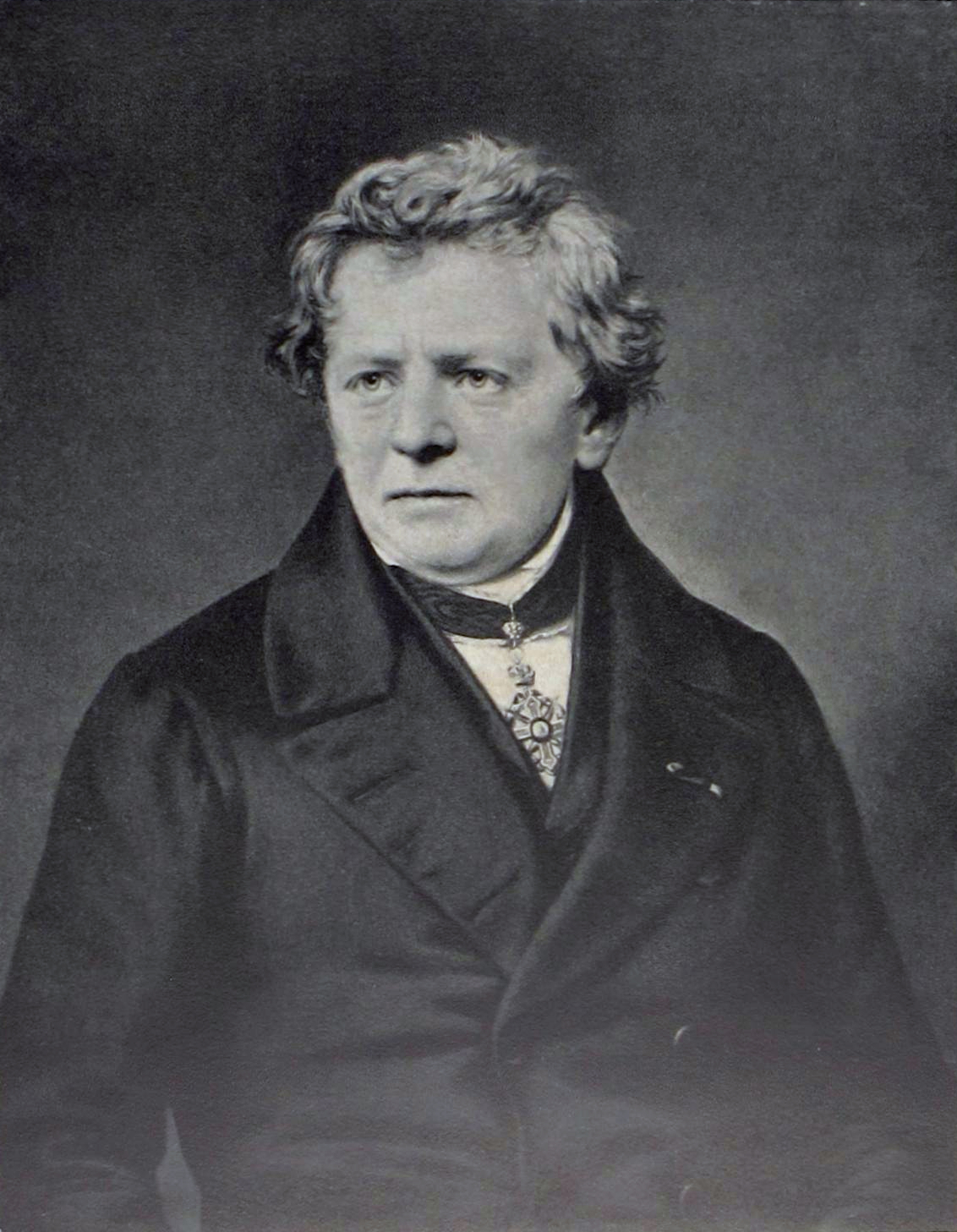
His first experiments, using a voltaic pile as the source, gave him trouble, because the pile’s output drifted as it ran down and polarised — the very thing that made the early galvanic experiments so slippery. The breakthrough was a change of source. On the advice of colleagues Ohm switched to a thermocouple: a junction of two dissimilar metals (he used bismuth and copper) that produces a small, but remarkably steady, voltage when one end is heated and the other kept in ice. The Seebeck thermoelectric effect had been discovered only a few years before, and Ohm turned it to account as a battery that would not fade during a measurement. With a stable source in hand, he varied the length of the wire in the circuit and measured the current with a torsion-balance galvanometer of his own devising, reading the twist of a magnetic needle suspended on a fine wire.
The result, distilled from careful data, was a relationship of disarming simplicity: the current was proportional to the driving force and inversely proportional to the total length of the circuit — that is, inversely proportional to what he named its resistance. In 1827 he published the full mathematical theory in a book with a forbidding title, Die galvanische Kette, mathematisch bearbeitet — “The Galvanic Circuit, Mathematically Investigated.” Buried in its equations was the statement now drilled into every first-year student: current equals voltage divided by resistance. It also introduced, in embryo, the idea that a circuit has a “resistance” as a definite, measurable, additive property — the conceptual seed of the component this entire dive is about.
The reception was dismal. The German physical establishment of the day was under the sway of Naturphilosophie, a Romantic, deductive approach that distrusted the reduction of nature to arithmetic. One reviewer dismissed the work as “a web of naked fancies”; another called it the product of “an incurable delusion.” Ohm had gambled his career on the book winning him a university chair, and instead it earned him ridicule. He resigned his Cologne post in disappointment and spent years in relative obscurity, teaching at a Nuremberg polytechnic school.
Vindication came from abroad and from the young. Physicists in England, France, Russia and America, unencumbered by the Berlin dogma, tested Ohm’s law, found it sound, and built on it. Charles Wheatstone and others in Britain leaned on it heavily as telegraphy grew into an industry that lived or died by the resistance of long lines. By the time the Royal Society of London awarded Ohm its highest honour, the Copley Medal, in 1841 “for his researches into the laws of electric currents,” the German academies could no longer ignore him. He was at last given a proper professorship at Munich in his final years and died there in 1854, respected. When, in the decades that followed, the international community came to name the electrical units after their pioneers, the unit of resistance was called the ohm, symbol Ω — a rehabilitation more complete than the man himself had ever dared hope for. Every resistor value marked on every schematic in the world is, in the end, a small memorial to a ridiculed schoolteacher.
4.3 The rheostat and the bridge
A law of resistance is one thing; a way to measure resistance accurately is another, and the nineteenth century needed the second even more than the first, because the telegraph business turned resistance into money. A fault on a submarine cable thousands of miles long could be located by measuring resistance, if only resistance could be measured with precision. Two ideas from the 1830s and 1840s gave the century its tools, and both are bound up with the name of Charles Wheatstone.
Wheatstone — born in 1802, a Gloucester music-instrument maker’s son who became a professor at King’s College London and one of the fathers of the electric telegraph — had a genius for instruments and, it must be said, for putting his name on other people’s. Around 1843 he introduced and named the rheostat, coining the word from the Greek rheos (a stream or current) and statos (standing) — literally a device for “steadying the current.” His rheostat was a variable resistance made by winding wire onto a cylinder so that a movable contact could tap off more or less of it, the direct ancestor of the wirewound potentiometers and rheostats of Volume 10. The word entered the language and never left it.
The more consequential idea was the bridge. Here the historical record is blunt: the circuit that everyone calls the Wheatstone bridge was not invented by Wheatstone. It was devised in 1833 by Samuel Hunter Christie, a mathematician at the Royal Military Academy, who published it as a “diamond” method for comparing the resistances of wires in a paper on the magnetic and electrical properties of metals. Christie’s idea languished, little noticed, for a decade. In 1843 Wheatstone, in a Bakerian Lecture to the Royal Society, described the circuit, developed it, and put it to systematic use — and, crediting Christie only in passing, gave the arrangement the momentum that made it famous. The name stuck to the populariser, not the inventor, as names so often do.
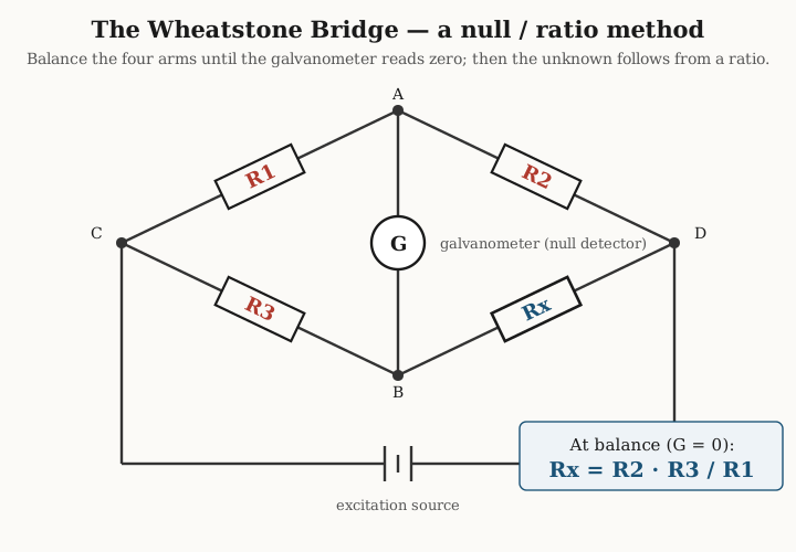
Why did the bridge matter so much? Because it is a null method, and null methods are the aristocrats of measurement. An ordinary ohmmeter measures resistance by passing a current and reading a voltage, so its accuracy is only as good as its current source, its meter’s calibration, and the stability of both. The bridge sidesteps all of that. Four resistances form a diamond; a battery drives one diagonal and a galvanometer bridges the other. The operator adjusts one calibrated arm until the galvanometer needle sits dead on zero — meaning the two midpoints of the diamond are at exactly the same potential and no current flows through the detector. At that instant the unknown resistance equals a simple ratio of the other three: Rx = R2·R3/R1. Notice what has vanished from that equation. The battery voltage does not appear, so it need not be known or stable. The galvanometer’s sensitivity does not appear, because it is only being asked the one question it answers best — is this zero or not? All that remains is the ratio of three resistances, which can be built from precision standards and known to a small fraction of a percent.
That is why the bridge, in its Wheatstone form and its four-terminal Kelvin refinement for very low resistances, was the precision resistance measurement from the 1840s until the digital era, and why it survives on the metrology bench to this day. The full family of bridge and null techniques — Wheatstone, Kelvin, and the substitution methods that beat them all for the finest work — is the subject of Volume 13. Here it is enough to see that by the middle of the nineteenth century the resistor had acquired both a governing law and a precision instrument to measure it by. What it did not yet have was an agreed unit, or a practical manufactured form. Both were coming.
4.4 Defining “one ohm”
It is a curious fact that the world had Ohm’s law for a generation before it could say, with authority, how big one ohm actually was. Every telegraph engineer measured resistance against his own reference coils, and one company’s “unit” did not match another’s. As undersea cables stitched the continents together in the 1850s and 1860s, this Babel became intolerable: a resistance measured in London had to mean the same thing when checked in Bombay.
The scramble to fix a standard is one of the founding episodes of modern metrology. In 1860 the German industrialist and inventor Werner von Siemens proposed a reproducible standard that anyone with a good laboratory could rebuild from scratch: the resistance of a column of pure mercury, one metre long and one square millimetre in cross-section, at the temperature of melting ice. Mercury was chosen because it is a liquid — it can be poured into a calibrated glass tube of known bore, so its geometry is exactly defined — and because it can be purified to a high and repeatable standard. The Siemens mercury unit was a real, physical, copyable thing, and it caught on; it works out to about 0.95 of the modern ohm.
The British Association for the Advancement of Science, alarmed that the telegraph industry was drifting without a common yardstick, took the matter in hand. Prompted by a paper from Latimer Clark and Charles Bright in 1861, the BAAS appointed a committee — its members included James Clerk Maxwell and William Thomson, later Lord Kelvin — to define and construct a resistance standard. Their approach was more ambitious than Siemens’: they sought an absolute ohm, one derived from mechanical and magnetic first principles rather than from an arbitrary tube of mercury, and then embodied it in a set of standard coils. Their reports through the 1860s wrestled the unit into being; by 1867 the committee was calling it simply the ohm. The name proposed for the man was made permanent for the unit.
For decades afterward the practical definition was tied back to mercury for reproducibility. An international conference of electricians at Paris in 1884 fixed a “legal ohm” as the resistance of a mercury column 106 centimetres long; the International Electrical Congress at Chicago in 1893 refined this into the international ohm — a mercury column 106.3 cm long, of mass 14.4521 grams, at 0 °C. That oddly specific mass, rather than a stated cross-section, was a clever way to pin down the geometry precisely: fix the length and the mass of a uniform tube of a material of known density, and its bore follows. The international ohm reigned as the working definition into the twentieth century.
A mercury column is a fine definition but an awkward thing to keep on a shelf and carry to a customer. What metrology needed was a transportable standard resistor — a coil of wire that would hold its value indefinitely. Ordinary metals were hopeless: copper’s resistance climbs by roughly four parts in a thousand for every degree Celsius, so a copper standard is really a thermometer in disguise. The breakthrough was a new class of alloy with almost no temperature dependence at all, and it came from an American. Edward Weston, the Newark instrument-maker whose name still graces the standard cell, discovered in the late 1880s that certain copper-nickel alloys had a very low, and even negative, temperature coefficient. His “Alloy No. 2” became known as constantan — the name says it plainly, a constant resistance. In 1892 he improved on it with an alloy of copper, manganese and nickel he called manganin, which has a temperature coefficient near zero around room temperature and, crucially, a very small and stable thermoelectric voltage against copper. Manganin was, and remains, the material of the precision resistor. From 1901 until 1990, banks of manganin standard resistors — first the German Reichsanstalt pattern, then the sealed oil-filled Thomas type maintained by the U.S. National Bureau of Standards — served as the legal embodiment of the ohm in America and much of the world. Only in 1990 did the physical artefact finally yield to physics itself, when the ohm was tied to the quantum Hall effect discovered by Klaus von Klitzing in 1980 — a resistance that emerges, exact and unchanging, from fundamental constants of nature. The metals manganin and constantan, and the story of why alloys resist so stubbornly and so stably, are taken up again in Volumes 2 and 8. For the historian of the part, the point is that by 1900 the resistor had a law, an instrument, a unit, and a class of alloys that could realise a value and hold it. What it still lacked was cheapness.
4.5 The carbon era
The precision standards of the metrologists were never meant to sit in a radio. They were laboratory jewels — hand-wound, oil-bathed, priced accordingly. The explosion of radio and then of electronics in the first half of the twentieth century demanded something utterly different: a resistor that cost pennies, could be made by the million, and was good enough — not perfect — for a plate load or a grid leak in a vacuum-tube set. The answer was carbon.
Carbon is a natural for the job. It conducts, but poorly and adjustably: mix finely divided carbon or graphite with an insulating binder such as clay or resin, and the resistance of the mixture can be dialled anywhere from a few ohms to many megohms simply by changing the ratio. Mould the mixture into a small cylinder, bake it hard, press a wire lead into each end, and dip the whole in a coat of insulating lacquer, and you have a carbon composition resistor — cheap, rugged, and manufacturable in endless values. The technique matured in the 1920s and 1930s. In the United States the dominant maker was Allen-Bradley of Milwaukee, whose founder’s brother, Lynde Bradley, patented a hot-moulding process in 1931 that turned out remarkably consistent parts; the little brown Allen-Bradley “hot-moulded” resistor, with its colour bands, became one of the most recognisable objects in twentieth-century electronics. Speer Carbon, Stackpole, IRC and Ohmite were the other great American names; abroad, firms like Erie and Morganite filled the same role.
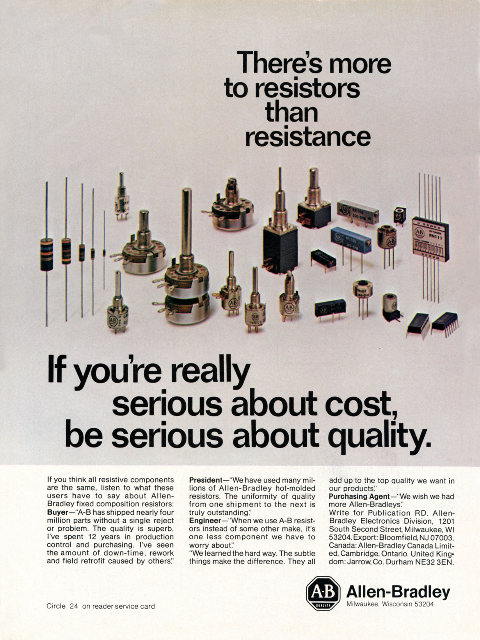
Through the Second World War the moulded carbon-composition resistor was simply the resistor. It went into every radio, radar set, and piece of military electronics by the hundreds of millions. Its great virtue, beyond cheapness, was ruggedness under abuse: because the resistive carbon fills the entire body rather than living as a thin skin on the surface, a carbon-composition part can absorb a large, brief pulse of energy — a surge that would blow a delicate film resistor to a crisp — by spreading the heat through its whole bulk. That single property has kept carbon-composition resistors in production, in specialist quantities, right up to the present day, prized in the snubber and pulse-handling roles that Volume 7 examines.
But the moulded carbon part had vices that grew more intolerable as electronics grew more demanding. Its tolerance was loose — ±10 or ±20 percent was normal, ±5 percent was a good day — because moulding a carbon-clay mix to an exact resistance is inherently imprecise. It drifted: the resistance crept upward over years and jumped around with temperature, since carbon’s own resistivity is temperature-sensitive and the binder ages. It was hygroscopic — it drank moisture from humid air, which changed its value and could be only partly held off by the lacquer coat. And it was noisy: a carbon-composition resistor generates far more electrical hiss than the fundamental thermal minimum, because current squeezing between countless little carbon granules produces a restless “excess” or current noise that a low-level audio or instrumentation stage cannot tolerate. Every one of these faults — tolerance, drift, moisture, excess noise — is dissected quantitatively in Volume 3 and Volume 7. Together they set the agenda for everything that came next. The industry spent the second half of the twentieth century systematically engineering the carbon composition resistor’s vices out of existence, and the first casualty was carbon itself.
4.6 The wirewound tradition
Running in parallel with the cheap carbon part, and never displaced by it, was an older and more aristocratic line: the wirewound resistor. If you need a resistance you can trust — trust to a tenth of a percent, trust to hold its value over decades, trust to carry serious power without complaint — you make it the way Wheatstone made his rheostat: by winding a measured length of resistance wire onto a form.
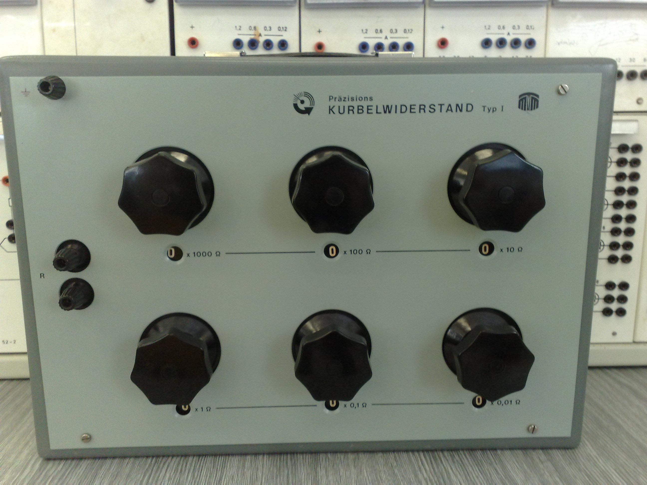
The wirewound resistor split early into two families that answer to two different masters. The first is precision. Wind manganin or a similar low-tempco alloy carefully onto a stable ceramic former, adjust the length to hit the target value exactly, and you have a resistor with a tolerance measured in hundredths of a percent and a temperature coefficient of a few parts per million per degree — orders of magnitude better than any carbon part. These are the resistors inside the standard-resistance boxes, the decade boxes, and the ratio arms of the very Wheatstone and Kelvin bridges described above. The measurement instrument and the components it measured were, in this precision world, made of the same wire.
The second family is power. Here the wire is a tough, heat-tolerant alloy — nichrome and its relatives — wound onto a rugged ceramic tube and often encased in vitreous enamel or a finned aluminium housing that can be bolted to a chassis for heat-sinking. These are the load resistors, the dynamic-braking banks, the bleeder resistors across high-voltage supplies, the motor-starting rheostats — the resistors that must turn tens or hundreds of watts into heat without catching fire. A power wirewound resistor is, frankly, a heating element with a calibrated value, and its lineage runs straight back to the resistance coils of the Victorian telegraph and power stations. Its one electrical liability is that a coil of wire is also an inductor, so an ordinary wirewound part misbehaves at high frequency — a problem solved with clever reverse-wound “non-inductive” (Ayrton-Perry) windings covered in Volumes 8 and 11.
The wirewound tradition is worth pausing on because it puts the whole history in perspective. The film and chip revolutions to come did not replace wirewound resistors; they carved off the vast middle of the market — the ordinary quarter-watt, few-percent resistor of everyday circuitry — and left the two extremes to wire. To this day, when a designer needs the very best stability or the ability to dissipate real power, the answer is still, often, a coil of alloy wire on a ceramic form, made much as it would have been a century ago. The resistor’s history is not a simple march from old to new; it is the fanning out of a family, each branch surviving in the niche it serves best.
4.7 The film revolution
The middle of the market — the billions of ordinary resistors — was won by film. The insight was simple and powerful: instead of making a resistor out of a solid bulk of resistive stuff, deposit a thin film of it onto an insulating rod and use the film’s surface as the resistance. A thin film gives the manufacturer two things the moulded carbon part could never offer. First, control: the film’s thickness and composition can be held far more precisely than a moulded mixture, and — the master stroke — its value can be trimmed after deposition by cutting a helical spiral groove into the film with a grinding wheel or, later, a laser, which lengthens and narrows the current path until the resistance rises to exactly the wanted value. Second, low noise: a continuous film has none of the granule-to-granule turbulence that makes carbon composition hiss, so film resistors are dramatically quieter.
The first step was still carbon, but carbon deposited rather than moulded. Cracked-carbon or pyrolytic carbon-film resistors, developed and refined from the 1930s onward, were made by decomposing a hydrocarbon gas at high temperature so that a hard, uniform film of pure carbon deposited onto a ceramic rod. Helically trimmed and lacquered, these carbon-film parts held tighter tolerances than carbon composition, drifted less, and cost little more; through the 1950s and 1960s they steadily displaced the moulded part in ordinary commercial and consumer gear. The familiar small beige resistor of a 1970s circuit board is very often a carbon-film part.
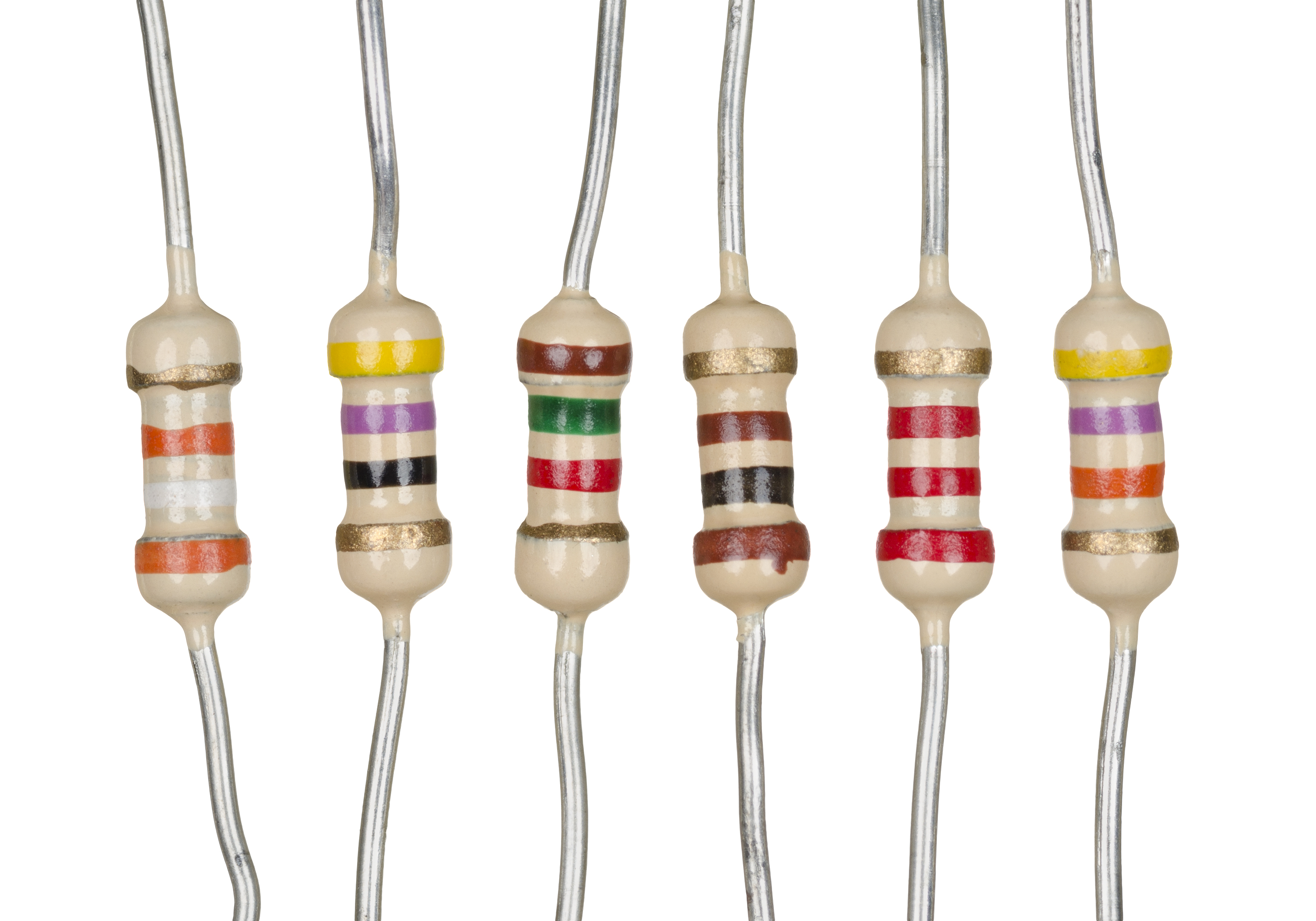
The decisive advance came after the Second World War with metal film. Instead of carbon, a thin layer of a metal or, most commonly, a nickel-chromium (nichrome) alloy is vacuum-deposited or sputtered onto a high-grade ceramic rod, then helically trimmed. Metal film brought a combination the industry had been chasing for a century: tight tolerance (±1 percent became ordinary, ±0.1 percent achievable), a low and controllable temperature coefficient (tens of parts per million per degree, against hundreds for carbon), genuinely low noise, and good long-term stability. The military drove the technology hard — the mil-spec precision resistor, the RN-series metal-film part built to standards like MIL-R-10509 and later MIL-R-55182, set a benchmark of reliability and stability that the commercial world inherited. A close cousin, the metal-oxide film resistor (typically tin oxide), traded a little precision for better heat and surge tolerance and filled the small-power niche.
The cumulative effect was a quiet revolution in what a designer could take for granted. Where the tube-era engineer designed around a resistor that might be 20 percent off and drifting, the transistor-era engineer could specify a 1 percent metal-film part and forget about it — could build precision dividers, accurate gain-setting networks, and stable references out of ordinary catalogue components. The rise of tight-tolerance film as the default, rather than a costly special, is one of the under-celebrated enablers of modern precision electronics. The construction and trimming of every one of these film types — carbon film, metal film, metal oxide — is the substance of Volumes 5 and 7.
4.8 Miniaturisation and the chip
Film had transformed what was inside the resistor. The last revolution transformed its shape, and it was driven not by the resistor itself but by the way electronics were assembled. Through the 1960s, circuits were built by pushing the wire leads of axial components through holes in a printed board and soldering them on the far side — through-hole construction. It was reliable but stubbornly manual and space-hungry: every leaded resistor needed two drilled holes, bent leads, and board area for its long body. As integrated circuits packed ever more function into ever less space, the humble leaded resistor became the bottleneck.
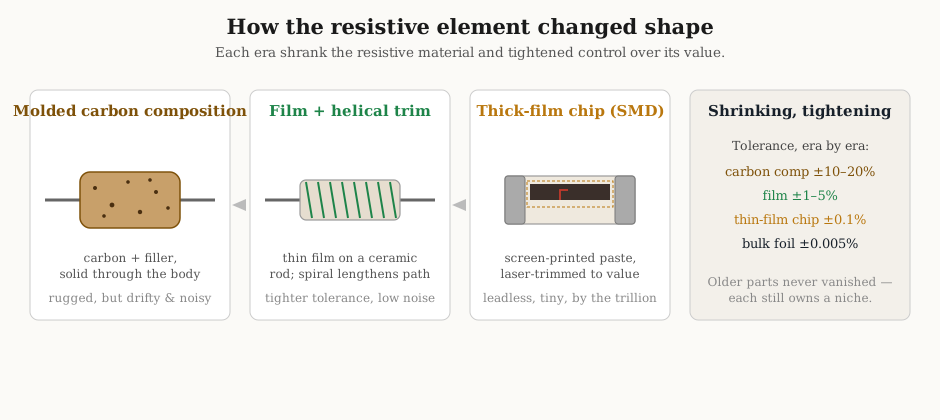
The answer was to abolish the leads entirely. A surface-mount resistor is a tiny leadless block that sits on top of the board and is soldered directly to flat copper pads, with no holes at all. The workhorse form is the thick-film chip resistor: a small rectangular tile of 96-percent-alumina ceramic onto which a resistive paste — finely divided ruthenium oxide and glass frit suspended in an organic vehicle — is screen-printed, exactly as ink is screen-printed onto a T-shirt. The printed tile is fired at high temperature to burn off the vehicle and fuse the resistive glass, metallised end-caps are added to make the solder terminations, and each resistor is laser-trimmed to value by cutting a tiny kerf into the fired film while its resistance is monitored in real time. A protective glass overcoat and a printed value code finish it. Sony is generally credited with the first surface-mount resistors in the mid-1960s, and through the 1970s the thick-film chip settled into the form it still has today — a design so well-matched to the problem that it has changed remarkably little in half a century.
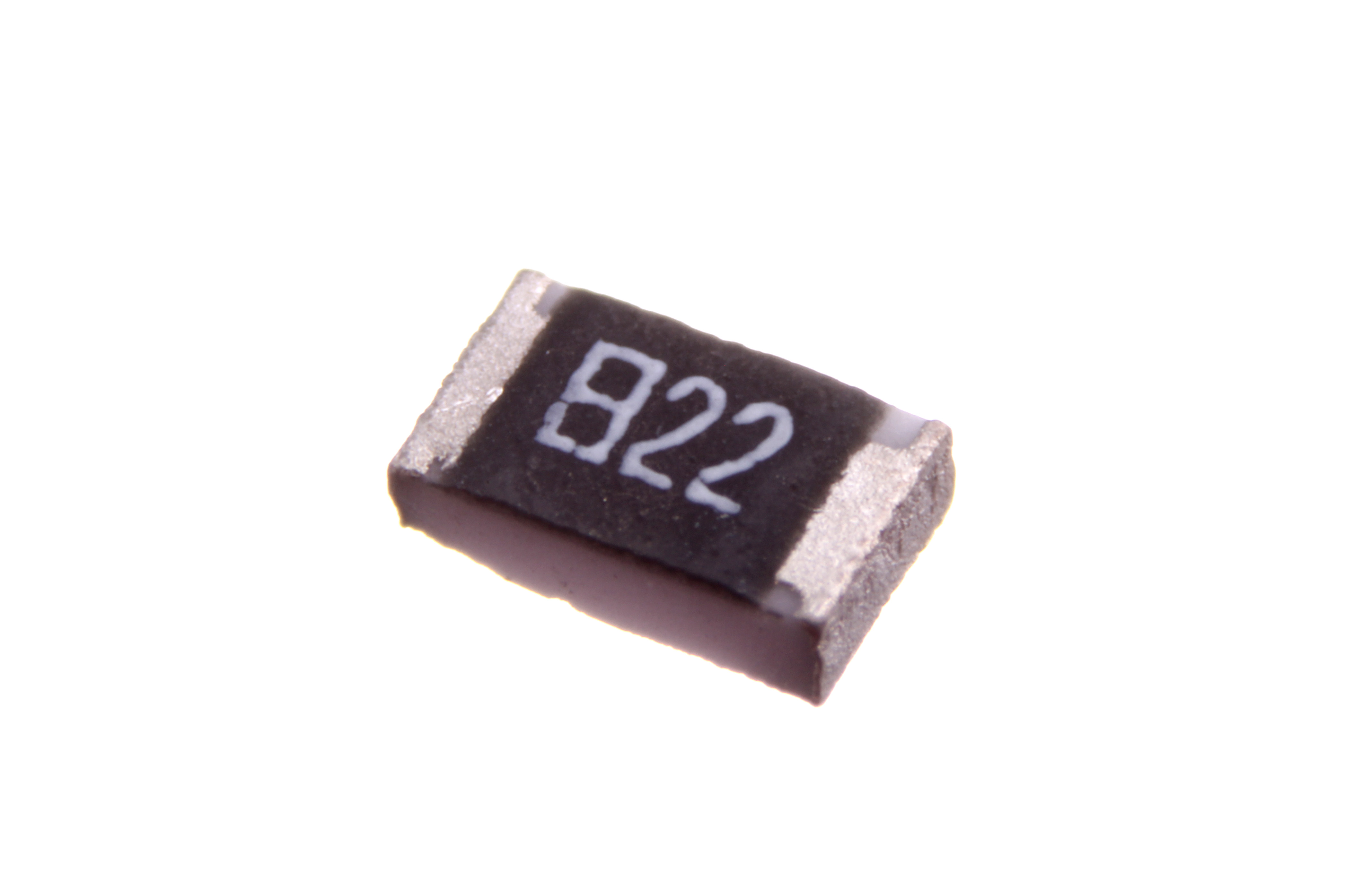
The chip resistor’s advantages compounded on one another. Being leadless and tiny, it could be placed by machine — a pick-and-place head can set tens of thousands per hour — which slashed assembly cost and made possible the dense, complex boards inside every phone and computer. Its case sizes marched steadily downward, each named by a code giving its dimensions in hundredths of an inch: the 1206 gave way to the 0805, then the 0603, the 0402, the 0201, and the barely-visible 01005, a speck a third of a millimetre long that must be handled by machine because human fingers cannot. (The codes, and the three- and four-digit value markings printed on the larger chips, are decoded in Volume 6.) Being leadless also improved the part electrically, stripping away the lead inductance that limited the leaded resistor at high frequency — a benefit that matters more and more as circuits run faster.
The result is a manufacturing phenomenon almost without parallel. The chip resistor is now made in numbers that are hard to hold in the mind: the Asia-Pacific region alone shipped on the order of two trillion chip resistors in a single recent year, and the figure climbs annually. It is, by raw unit count, very likely the most-manufactured discrete artefact in human history. The overwhelming majority are anonymous thick-film chips costing a small fraction of a cent, placed by robots onto boards no human hand will ever touch — the direct, shrunken, industrialised descendants of Allen-Bradley’s little brown cylinder.
4.9 The modern industry, and where it goes next
The resistor industry today is concentrated, global, and dominated by a handful of names that recur across every category of this dive. Vishay Intertechnology, assembled from a long series of acquisitions, spans the range from bulk-foil precision parts to commodity chips. Yageo of Taiwan, having absorbed the former Philips passive-components business (Phycomp) and later Vishay’s own foil lines, is one of the largest chip-resistor makers on earth. KOA Speer, Panasonic, Rohm, Murata, Samsung Electro-Mechanics, TE Connectivity, Bourns, TT Electronics, and Ohmite each own strong positions — some in high-volume chips, some in power and specialty parts. At the precision apex sit the specialists: Susumu and again Vishay for thin-film chips, Caddock and Vishay’s Foil Resistors division for the ultra-stable bulk-metal-foil parts whose story is told in Volume 8. The names change with each merger, but the shape of the industry — a broad base of commodity chip makers, a narrow spire of precision houses — has held for a generation.
Where does an object this old and this mature go from here? Not, mostly, toward a new physical principle; Ohm’s law is not going to be improved upon. The frontier is at the two extremes and in integration. At the precision end, thin-film chips — sputtered nichrome rather than screen-printed thick film — push tolerance toward ±0.05 percent and temperature coefficients toward a handful of parts per million on a surface-mount part, while bulk metal foil holds the absolute record for stability, tempco, and low noise for the instruments that need the very best. At the power end, ever more compact surface-mount packages learn to shed serious wattage, and metal-element current-sense shunts with milliohm and sub-milliohm values proliferate as every power supply and battery system meters its own current (Volume 11). And increasingly the resistor is disappearing into other things: resistor networks and arrays put many matched elements in one package (Volume 10); embedded or integrated resistors are printed directly into the inner layers of a printed board or fabricated on a silicon die, so that the discrete part vanishes altogether into the substrate.
And yet, for all of that, the essential object endures unchanged in spirit. A resistor is still a length of poorly conducting material with a terminal at each end, obeying the proportionality a Bavarian schoolteacher wrote down in 1827. The metrologist’s mercury column has become a quantum-mechanical constant; the moulded carbon cylinder has become a laser-trimmed speck of glass; the hand-wound standard has become a robot’s two-trillion-a-year output. But between those terminals, the physics is Ohm’s, and the value obeys his law to the last decimal place. The resistor is the oldest idea in electronics, and the industry still makes it by the trillion — a small, humble, indispensable component whose two-century history is, in miniature, the history of electrical engineering itself.
Comments (0)