Resistors · Volume 9
Power and Derating
9.1 The number that decides how long the part lives
Every earlier volume treated the resistor as an ohmic value with a set of second-order imperfections — a tolerance, a temperature coefficient, some noise, a whisker of stray inductance. This volume is about the one specification that is not about accuracy at all but about survival: the power rating, and the derating rules that surround it. A resistor does exactly one thing with the electrical energy it is handed — it turns it into heat. The power rating is the promise the manufacturer makes about how much heat the part can make, continuously, before it cooks itself. Get that promise wrong and the most carefully chosen 0.1% metal-film resistor drifts, chars, and finally opens; get it right, with margin, and the humblest carbon film outlives the circuit around it. This is the thermal life of the resistor, and it is where more designs quietly fail in the field than almost anywhere else.
The reason it fails quietly is that a resistor rarely dies the instant it is overloaded. It gets hot, its value drifts up, its coating discolours, its solder joints fatigue, and months later it opens on a cold morning when the mechanical stress of a thermal cycle finally cracks the tired element. By then the schematic looks innocent, because on paper the part was “within its rating.” The trap is that the rating printed on the datasheet is not the rating in the circuit. The datasheet number is measured on a bench, in still air, at a stated temperature, with the part mounted a stated way. The moment that resistor is soldered onto a warm board inside a sealed enclosure next to a voltage regulator, its real allowable dissipation is a fraction of the headline figure. Understanding that gap — and designing for it — is the whole subject.
9.1.1 What the power rating actually means
The power rating (also called the rated dissipation or rated power, symbol P_R, in watts) is the maximum power the resistor may dissipate continuously while its hottest internal point stays at or below the material’s safe limit — provided the part is operated under the exact reference conditions the datasheet specifies. Three conditions are always part of the definition, and all three are routinely forgotten.
First, a stated ambient temperature. For the vast majority of general-purpose film resistors the rating is quoted at 70 °C ambient — the temperature of the air (or the board) immediately around the part. A minority of parts, and almost all bare wirewound and power types, are rated at 25 °C instead, which flatters the number because there is more thermal headroom to give away. The two conventions are not interchangeable: a “0.25 W at 70 °C” film chip and a “0.25 W at 25 °C” power resistor are not the same promise, and comparing them by the watt figure alone is an error.
Second, a specified mounting and environment. A leaded resistor is typically rated in free air with leads of a stated length (often bent to a stated spacing) that themselves conduct heat away. A surface-mount chip is rated on a specified test board — a defined copper pad area on FR-4 of stated thickness, because for a chip the printed-circuit board is the heatsink. Change the copper and you change the rating.
Third, the number is a continuous rating, not a peak. It is the steady-state dissipation the part can hold indefinitely, not the energy it can absorb in a brief pulse (which is a separate and usually far larger number, discussed later).
So the honest reading of “0.25 W” on a film resistor is: a quarter of a watt, forever, in 70 °C air, with leads of the reference length. What it emphatically does not mean is “a quarter of a watt on any board at any temperature.” It is not a rating at 25 °C on a hot board inside a hot box. Treating the headline watt as an all-conditions guarantee is the single most common way engineers overload resistors while believing they have not.
9.1.2 Temperature rise and the hot spot
To see why the rating must fall as the surroundings warm, follow the heat. When a resistor dissipates power P, that heat is generated in the resistive element — the thin film, the wound wire, the carbon slug — and must travel out to the surrounding air. It does so across a chain of thermal resistances, each measured in degrees Celsius per watt (°C/W), the thermal analogue of electrical resistance. The heat crosses from the hottest internal point (the hot spot) to the body surface across an internal thermal resistance, then from the body to the ambient air across an external one. Just as voltage drops across an electrical resistance in proportion to current, temperature rises across a thermal resistance in proportion to heat flow:
ΔT = P × Rθ
The hottest point in the part therefore sits above ambient by the power multiplied by the total thermal resistance from hot spot to air. That hot-spot temperature — not the average body temperature, and certainly not the ambient — is the real limit. The manufacturer sets a maximum element (or body) temperature, and everything about the rating is engineered so that at rated power in the reference ambient, the hot spot just reaches that ceiling. For ordinary film resistors the ceiling is commonly 155 °C; for many power and wirewound types it is 275 °C, and some families sit at 175 °C. These are not arbitrary: they are the temperatures at which the coating, the film adhesion, or the terminations begin to degrade over the rated life.
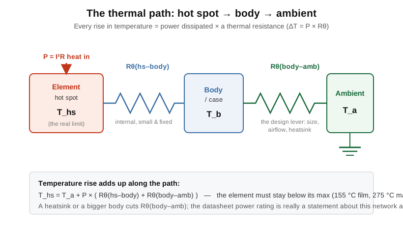
That total thermal resistance is not usually printed on the datasheet, but it can be read straight out of the rating, and doing so makes the whole scheme concrete. The rating says the part reaches its 155 °C ceiling when dissipating 0.25 W in a 70 °C ambient — a rise of 155 − 70 = 85 °C at a quarter watt. The thermal resistance from hot spot to air is therefore Rθ = ΔT / P = 85 / 0.25 ≈ 340 °C/W for a typical leaded quarter-watt film part. That one number is the part’s entire thermal character: every watt it dissipates lifts its hot spot 340 °C above the surrounding air. Dissipate 0.1 W and the hot spot sits 34 °C above ambient; in 70 °C air it reaches 104 °C, comfortably under the ceiling. Dissipate the full 0.25 W in that same air and it reaches 155 °C exactly — which is precisely what the rating promised. The reason a bigger body, a heatsink, or moving air raises the allowable power is that each of them lowers this Rθ, so the same temperature rise buys more watts. It is the single lever the designer has, and the packages later in this volume are all ways of pulling it.
The consequence is immediate. If the maximum hot-spot temperature is fixed, and the ambient rises, then the allowable temperature rise — and therefore the allowable power — must shrink by exactly the amount the ambient took away. That relationship, drawn out, is the derating curve.
9.2 The derating curve — the central diagram
The derating curve is the single most important picture in this volume, and any engineer who reads only one figure should read this one. It plots the percentage of rated power the part may dissipate against the ambient temperature. Its shape is always the same: a flat plateau at 100% up to the rated ambient, then a straight line falling to zero at the maximum element temperature.
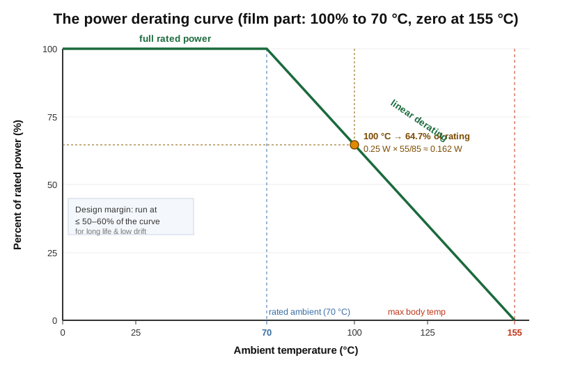
Reading it is simple once its two anchor points are clear. The curve is flat at 100% from low temperatures up to the rated ambient, because below that point there is thermal headroom to spare and the full rating applies. At the rated ambient — 70 °C for a typical film part — it begins to fall, and it falls linearly to zero power at the maximum element temperature, because at that ambient the part is already at its ceiling with no dissipation at all, so it can accept none. The slope of the line is fixed by geometry: it loses 100% of the rating over the span from the rated ambient to the maximum temperature. For the film part in the figure, that span is 155 − 70 = 85 °C, so the part sheds roughly 1.18% of its rating for every degree the ambient rises above 70 °C.
9.2.1 The worked 100 °C example
Consider the workhorse case: a 0.25 W resistor rated at 70 °C, with a maximum body temperature of 155 °C, that a designer wants to run at a 100 °C ambient — the sort of temperature found inside a poorly ventilated enclosure or near a heat source. The derated power is the rating scaled by how much of the temperature span remains above the operating ambient:
P_allowed = P_R × (T_max − T_ambient) / (T_max − T_rated)
P_allowed = 0.25 W × (155 − 100) / (155 − 70)
P_allowed = 0.25 W × 55 / 85
P_allowed = 0.25 W × 0.647 ≈ 0.162 W
The quarter-watt part, at 100 °C, is really a 0.162 W part — it has quietly lost more than a third of its rating simply because the air around it is warmer than the bench where it was rated. Push it to a 130 °C ambient and the same arithmetic gives 0.25 × 25/85 ≈ 0.074 W, less than a third of the nameplate. This is why “it’s only dissipating 0.2 W in a quarter-watt part, so it’s fine” is a dangerous sentence: at anything above the low-70s it is not fine at all.
9.2.2 Why designers build in margin
The derating curve is the absolute limit — the line beyond which the part is being abused. No experienced designer works up to it. The universal rule of thumb is to run a resistor at no more than 50 to 60% of its derated capability, and for anything meant to last decades or to hold a precision value, considerably less. There are three reasons. Reliability first: the failure rate of a resistor climbs steeply with hot-spot temperature, and every degree cooler buys life; the classic reliability models roughly halve a part’s useful life for each 8 to 10 °C of extra temperature. Stability second: a hot resistor drifts. The permanent shift in value after long operation — the load-life stability — grows with operating temperature, so a 0.1% resistor run hot no longer holds 0.1%. Third, the ambient the datasheet assumes almost never matches the ambient the part actually sees. The datasheet says 70 °C in free air; the part lives on a board that is already at 60 °C from everything around it, inside a box with no airflow, next to a regulator radiating its own heat. The “ambient” for the derating curve is the temperature at the resistor, not the temperature outside the equipment — and inside a sealed enclosure those can differ by 30 or 40 °C. Designing with margin is how a competent engineer absorbs that unknown without having to measure it.
There is a subtler point hiding in that margin. Because the derating line is linear, the cost of the last few watts is disproportionate: near the rated ambient a resistor still holds its full rating, but every degree of enclosure heating thereafter shaves a fixed slice off, and a design that is comfortable at 25 °C on the bench can be over its limit at 85 °C in a sealed box even though nothing in the circuit changed. This is why bench testing so reliably under-reports thermal problems — the bench is the one place the ambient is genuinely low and the air genuinely still-but-cool. The disciplined approach is to establish the worst-case ambient at the part first, read the derated ceiling there, and only then pick a size, rather than picking a size at room temperature and hoping the enclosure is kind.
9.3 Surface-mount thermal reality
For a leaded resistor, the leads and the surrounding air carry the heat away. For a surface-mount (SMD) chip resistor there are no leads and there is barely any air worth mentioning — the heat leaves almost entirely by conduction into the solder joints, the copper pads, and the board. The printed-circuit board is the heatsink. That single fact governs SMD power ratings, and it makes them far more situational than leaded ratings.
Because the board does the cooling, the power rating of a chip scales with its size — a larger chip has more termination area and more footprint through which to dump heat — and with the copper it is soldered to. The nominal ratings, quoted at 70 °C on the vendor’s reference footprint, form a familiar ladder:
Table 1 — reference footprint, form a familiar ladder
| Imperial | Metric | L × W (mm) | Nominal power at 70 °C |
|---|---|---|---|
| 0201 | 0603 | 0.6 × 0.3 | 1/20 W (50 mW) |
| 0402 | 1005 | 1.0 × 0.5 | 1/16 W (63 mW) |
| 0603 | 1608 | 1.6 × 0.8 | 1/10 W (100 mW) |
| 0805 | 2012 | 2.0 × 1.25 | 1/8 W (125 mW) |
| 1206 | 3216 | 3.2 × 1.6 | 1/4 W (250 mW) |
| 1210 | 3225 | 3.2 × 2.5 | 1/2 W (500 mW) |
| 2010 | 5025 | 5.0 × 2.5 | 3/4 W (750 mW) |
| 2512 | 6432 | 6.4 × 3.2 | 1 W |
These numbers are correct only on the stated board. Two SMD-specific realities bend them. The first is copper area: a chip mounted on generous pours of heavy copper runs cooler and can be rated higher, while the same chip on hair-thin traces to a thin board runs hotter and must be derated below the table. Heavier copper (2 oz rather than 1 oz) and larger pad or fill areas measurably raise the usable power; some vendors publish a family of ratings against pad area for exactly this reason. The second is that the reference “ambient” is best read as the board temperature, not the air temperature. Because the chip is bonded to the board, what matters is how hot the copper under it is, and a busy board can be far above room temperature. For this reason many manufacturers derate power chips against terminal temperature rather than ambient — they specify the temperature measured at the solder termination itself, and give a derating curve from there, because that is the one temperature that actually reflects the heatsink the chip is bolted to. The practical upshot is that an SMD power rating is never a property of the resistor alone; it is a property of the resistor and the board it lives on, and it must be verified in the real layout.
9.4 Pulse and surge — energy, not just power
Everything so far concerned continuous dissipation. A great many resistors, though, never see steady power at all — they are hit by brief, violent pulses: the inrush that charges a bulk capacitor at power-on, the load-dump transient when an alternator’s load is thrown off, an electrostatic-discharge (ESD) strike, a nearby lightning surge coupled through a line. For these the relevant question is not “how many watts forever” but “how much energy in how short a time,” and the answer is governed by entirely different physics.
For a pulse much shorter than the time it takes heat to diffuse out of the element — a few milliseconds and below for most parts — essentially none of the heat escapes during the pulse. The element behaves adiabatically: it simply stores the energy as a temperature rise of its own thermal mass. The limit is then set not by the steady-state thermal resistance to air but by how much energy the element’s mass can absorb before its hottest point reaches a destructive temperature. That is why a resistor’s single-pulse power capability can be 10 to 100 times its continuous rating for short pulses, and why manufacturers publish pulse-power-versus-pulse-width curves rather than a single pulse number: the shorter the pulse, the higher the permissible peak power, tapering back toward the continuous rating as the pulse lengthens past the part’s thermal time constant.
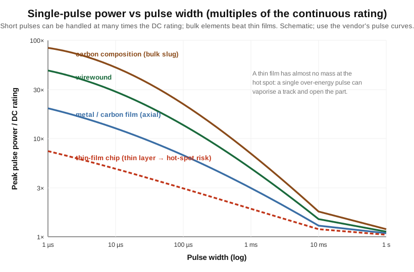
Which constructions survive pulses is decided by where the energy goes. A carbon composition resistor is a solid slug of conductive material; the pulse energy spreads through the whole bulk of the body, so the local temperature rise is modest and the part shrugs off surges that would destroy a film. This — not its electrical quality, which is poor — is why carbon composition survives in surge, crowbar, and pulse-clamping roles long after film displaced it everywhere else. Wirewound parts are similarly robust: a substantial mass of resistance wire absorbs a lot of energy before any point gets too hot. At the opposite extreme, a thin-film resistor puts all of its resistance in a layer a fraction of a micrometre thick, patterned into a narrow serpentine track. A pulse deposits its energy in that vanishingly small mass, and any local constriction — the narrowest point of a laser-trimmed track — becomes a hot spot that can reach vaporisation temperature and open the film in microseconds, even though the average body temperature barely moved. Thick-film chips sit in between, better than thin film but still no match for a bulk slug. The lesson for the designer facing inrush, load-dump, ESD, or lightning is to reach deliberately for a pulse-withstanding construction — a bulk, wirewound, or purpose-built pulse-rated part — and to size it from the vendor’s energy curves, never from the continuous watt figure.
9.5 Voltage rating — when volts, not watts, set the limit
There is a second ceiling on a resistor that the power rating does not describe at all: the maximum working voltage. This is the highest continuous voltage that may appear across the part, set not by heating but by the electrical strength of the element and its insulation — the point at which the voltage begins to arc across the body, track along the surface, or break down between the turns of a film’s trimmed spiral. Datasheets quote it as a maximum working voltage (sometimes with a higher, brief overload or insulation voltage alongside), and for a small film part it is commonly a few hundred volts — 200 V for many 0402/0603 chips, 250 to 500 V for 1/4 W leaded film, and so on up with body length.
For low and moderate resistances this voltage ceiling never bites, because the part reaches its power limit long before its voltage limit. But for high-value resistors it governs, and the crossover is worth internalising. The voltage that corresponds to the full power rating is V = √(P·R). As resistance climbs, that power-limited voltage rises with the square root of R, while the working-voltage ceiling stays fixed. Above some resistance the two lines cross, and beyond it the fixed voltage limit — not the power — decides how hard the part may be driven.
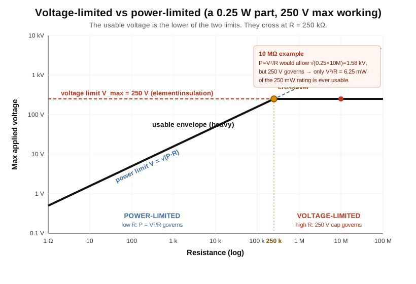
Take the worked case in the figure: a 0.25 W part with a 250 V maximum working voltage. The crossover is where √(0.25·R) = 250 V, i.e. 0.25·R = 62 500, so R = 250 kΩ. Below 250 kΩ the part is power-limited in the ordinary way. Above it, the voltage ceiling wins. Now take a 10 MΩ resistor from the same family. The power rating alone would suggest it can stand √(0.25 × 10 000 000) ≈ 1 580 V before reaching a quarter watt. But its element can only tolerate 250 V. At that 250 V limit the actual dissipation is V²/R = 250² / 10 000 000 = 6.25 mW — a fortieth of the 250 mW nameplate. In other words, in a high-voltage divider the 10 MΩ chip will never come close to its power rating; it will arc over first. This is why high-voltage resistors are built with long bodies (a longer creepage and clearance path withstands more volts) and why high-voltage strings are made from many resistors in series, splitting the total voltage so no single element exceeds its working limit. That construction — long HV bodies and series ladders, with the voltage-coefficient and corona considerations that go with them — is the subject of the specialty-resistor volume (Vol 11); here the point is simply that voltage and power are two separate ceilings, and on high-value parts the voltage one comes first.
9.6 Heat-sinking and the high-power packages
If a resistor must dissipate real power, the design problem becomes a heat-removal problem, and the answer is packaging that lowers the external thermal resistance — the body-to-air term in Figure 1. The ladder of standard ratings, from the sixteenth-watt chip to the kilowatt braking load, is really a ladder of cooling strategies.
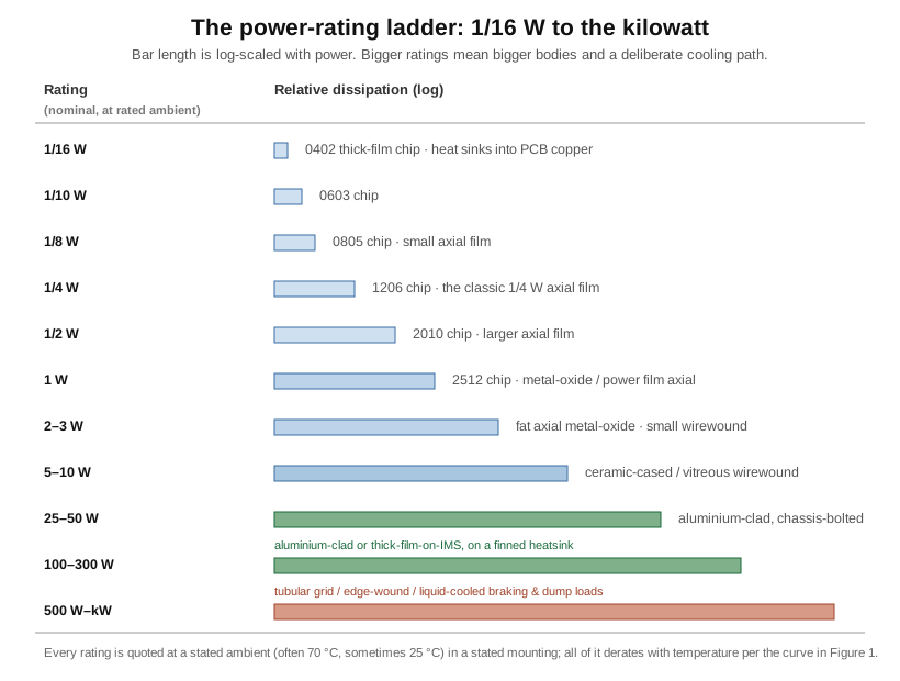
At the bottom, chips and small axial films rely on the board and the surrounding air. From a few watts upward, still air is no longer enough and the part is built to conduct its heat into metal. The classic power package is the aluminium-clad (aluminium-housed) resistor: a wirewound or thick-film element potted in a finned, anodised aluminium case with a mounting flange. Bolted to a chassis or heatsink, it sheds heat by conduction through the case rather than by convection from a coating, which is why a clad part the size of a thumb can carry 25 or 50 W where a bare wirewound of the same size manages a fraction of that.
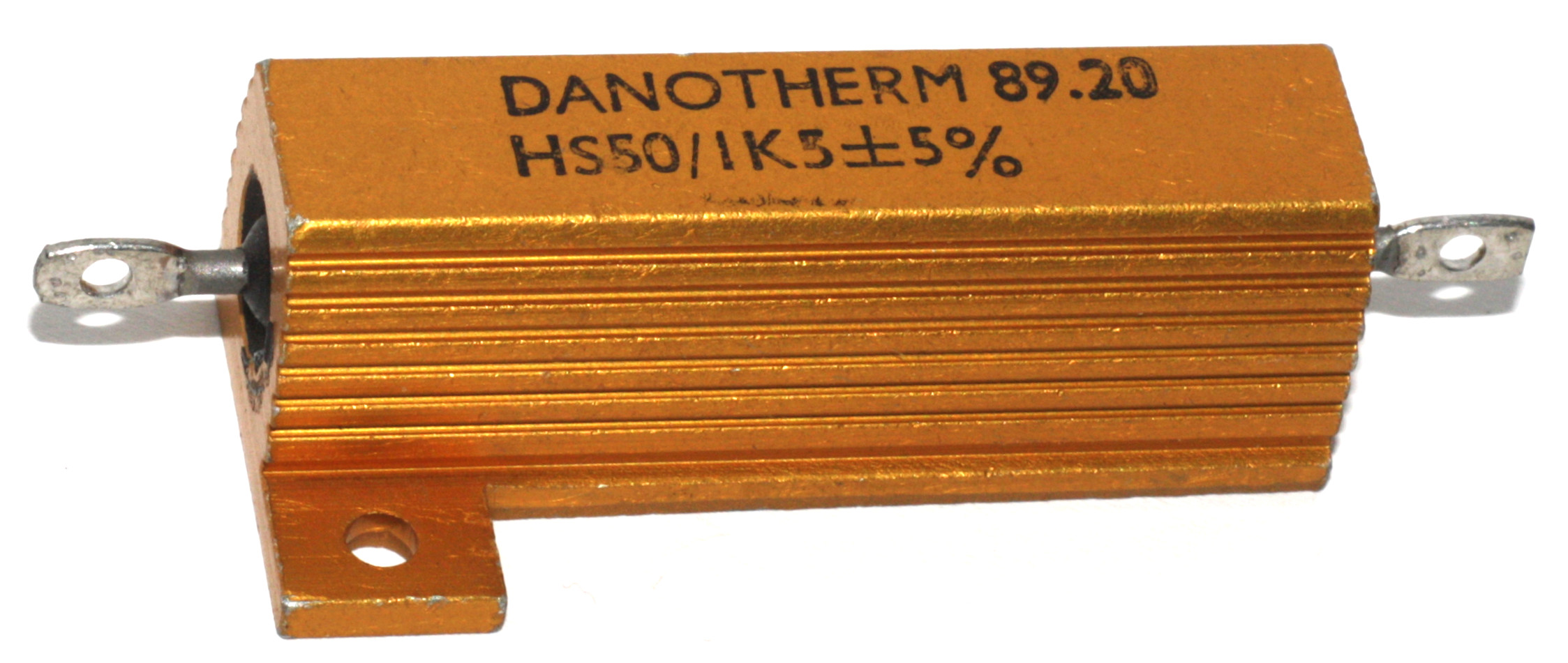
The rating of such a part is meaningless without its heatsink. Datasheets for clad resistors quote the full power only when the case is bolted to a heatsink of stated size (or to “infinite” heatsink), and give a much lower figure — often a third or less — for the part mounted in free air. Getting the rated performance depends on the details of the thermal joint: the mounting torque must be enough to press the flange flat against the sink, and a film of thermal compound (heatsink grease) or a thermal pad must fill the microscopic air gaps between case and sink, because trapped air is an excellent insulator. A clad resistor bolted down dry and loose can run at twice the temperature of the same part mounted properly, at the same dissipation.
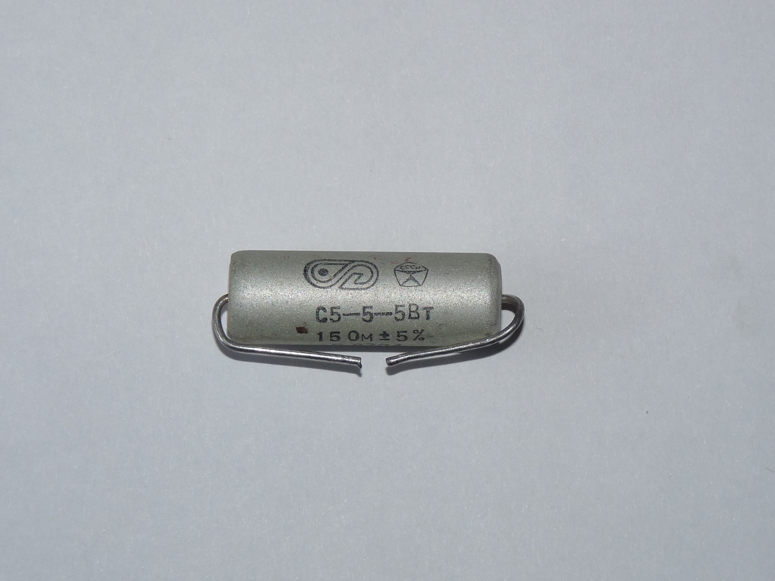
Between the small axial parts and the clad power types sits the family of ceramic-cased and vitreous-enamel wirewound resistors — resistance wire on a ceramic tube, coated in a vitrified glass enamel or cemented into a rectangular ceramic body — rated from a couple of watts to ten or more, cooled by convection and radiation from their own surface. These are the archetypal “power resistors” of the workbench: robust, tolerant of overload and pulse, and content to run visibly hot.
Above the clad parts, the highest power densities call for still more aggressive thermal paths. Discrete power resistors are built into TO-220 and TO-247 transistor packages — a thick-film element on a metal tab that bolts to a heatsink exactly like a power semiconductor, good for tens of watts in a tiny footprint. For the highest board-level densities the element is fired onto an insulated metal substrate (IMS) — a thin ceramic or polymer dielectric over an aluminium baseplate — so the heat spreads sideways and drops straight into the metal. At the very top of the ladder, where kilowatts must be dumped as in motor-drive braking, dynamic-braking grids, and dummy loads, resistors become open tubular grids, edge-wound ribbon banks, or liquid-cooled assemblies, forced-air or water taking the heat the way still air never could. In every case the electrical element is one already described in the construction and types volumes; what changes up the ladder is only the route the heat takes to get out.
9.7 Failure modes — what a burned resistor tells you
When a resistor is pushed past its thermal or voltage limits, it does not fail randomly; it fails in a small number of characteristic ways, and each leaves a legible signature. Reading that signature is a genuine diagnostic skill, because a failed resistor is often the symptom of a fault elsewhere — a shorted transistor, a failed regulator, a wrong value fitted — and the way it died points back at the cause.
The most common end state is open circuit. A resistor overrun far enough eventually burns through: the element chars, a track vaporises, a solder joint or end cap lets go, and the part reads infinite. Open failure is also the ordinary end-of-life mode of a healthy part run near its limit for years — the element slowly degrades until a thermal cycle finally cracks it. A milder, earlier symptom is resistance drift: a resistor operated hot but not lethally so will creep upward in value over time as its element oxidises or its film thins, so a resistor that measures well above its marked value (with no obvious damage) has usually been living too hot. The most dramatic mode is charring and burning: gross overload cooks the coating and the body, leaving the scorched, blistered, or blackened part that every bench-worker recognises.
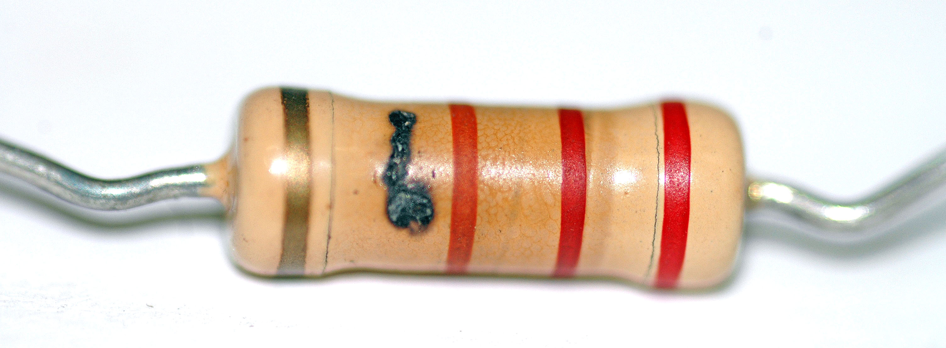
A charred resistor is a message. A part that is uniformly scorched along its whole body was carrying too much continuous power — the dissipation exceeded the derated rating and the whole element cooked. A part with a single localised burn or a blown spot, the rest of the body clean, was killed by a pulse or a voltage breakdown — energy dumped at one point faster than it could spread. Discolouration of the coating without a break says the part ran chronically hot and has probably drifted. And a part that has quietly gone open with no scorch at all often died of thermal fatigue at end of life rather than acute overload. In every case the appropriate response is to find why — because a resistor that failed from overload nearly always failed because something else changed the current or voltage it saw.
That destructive open-failure behaviour is also, deliberately, a safety feature in certain parts. Fusible and flameproof resistors are designed so that under gross overload they fail open, quickly, and without flame or ejecta — the resistor becomes the sacrificial fuse that protects the rest of the equipment, opening the circuit safely instead of catching fire. Flameproof coatings and fusible constructions are built precisely so the worst case is a clean open rather than a burning body, and they are specified wherever a resistor sits across a source that could drive it to destruction. Those safety-resistor constructions are taken up in detail in the specialty volume (Vol 11); the point here is that “fails open safely” is an engineered property, not luck, and it is chosen at design time.
9.8 Choosing a power rating — the working recipe
Everything in this volume collapses into a short procedure that a designer should run for every resistor that dissipates meaningful power. It has five steps, in order.
First, compute the worst-case continuous dissipation. Work out the actual power the part will dissipate — P = I²R, or V²/R, or V·I — at the worst-case combination of supply voltage, tolerance, and operating condition the circuit can present, not the nominal case. A current-limit or bleeder resistor sees its worst dissipation at maximum supply and minimum resistance; use those.
Second, derate for the real maximum ambient. Establish the highest temperature the air or board at the resistor will reach in service — inside the enclosure, after warm-up, in the hottest specified operating environment — and read the allowable power off the derating curve at that temperature, using the worked method above (P_R × (T_max − T_amb)/(T_max − T_rated)). This is the true ceiling, and it is usually well below the nameplate.
Third, add margin. Choose a rating such that the worst-case dissipation is no more than about 50 to 60% of that derated ceiling — less for precision, long-life, or inaccessible parts. The cost of the next size up is trivial next to the cost of a field failure.
Fourth, check the pulse and energy case. If the part sees inrush, load-dump, ESD, switching transients, or any surge, size it from the manufacturer’s pulse-power-versus-width or single-pulse-energy curves and choose a pulse-tolerant construction (bulk or wirewound, not thin film) — the continuous rating says nothing about survival here.
Fifth, check the voltage limit. Confirm that the maximum voltage across the part stays below its working-voltage rating, remembering that on high-value resistors this ceiling bites long before the power one; if it does not, split the voltage across a series string or choose a longer-bodied high-voltage part.
Run those five checks and the resistor will live as long as the equipment. Skip the second and third — the derating and the margin — and it will pass every bench test, ship, and fail in the field on a hot afternoon eighteen months later. The trade-offs between size, cost, and thermal headroom that this recipe balances are drawn together with every other selection criterion in the selection volume (Vol 12); the thermal life of the resistor, though, is decided here — by the power rating read honestly, the curve applied at the real ambient, and the margin that separates a design that works on the bench from one that works for years.
Comments (0)