Resistors · Volume 11
Specialty and Sensing Resistors
11.1 Two kinds of special
Nearly every volume of this dive has been about a resistor doing the one thing its name promises: holding a fixed number of ohms as steadily as its construction allows, drifting a few parts per million per degree, staying quiet, staying put. The whole engineering effort of a metal-film chip or a bulk-foil precision part is spent fighting change — the value that was trimmed at the factory is the value the circuit wants for the next twenty years. This volume is about the resistors that break that mold, and they break it in two very different directions.
The first group are still fixed resistors, still meant to hold a constant value, but built for jobs so extreme that an ordinary part would burn, flash over, corrupt the reading, or fail dangerously. These are the specialty resistors: the current-sense shunt that must read a milliohm through milliohm-scale contacts without lying about it; the high-voltage resistor whose body is long not for looks but to keep kilovolts from arcing across its surface; the fusible and flameproof parts engineered to die quietly and open the circuit rather than catch fire; the non-inductive power resistor; the humble zero-ohm jumper that is a resistor only in the sense that a machine can place it like one. Each is a fixed resistor pushed to an edge of the design space — extreme low value, extreme voltage, extreme fault behaviour.
The second group turns the whole idea inside out. These resistors are supposed to change. Their entire reason for existing is that some physical quantity in the outside world — temperature, voltage, light, mechanical strain — reaches in and moves their resistance in a known, repeatable way. Measure the resistance and you have measured the world. These are the sensing resistors, the transducers: the thermistor whose resistance tracks temperature, the varistor that watches the voltage across it and clamps a surge, the photoresistor that dims with the light, and the strain gauge whose resistance stretches with the metal it is glued to. They sit exactly on the boundary between the passive component and the sensor, and several of them are read with the very bridge and four-terminal techniques that the specialty resistors force on us.
So this volume runs in two halves. First the constant resistors built for extremes; then the resistors engineered to vary on purpose. The thread that ties them together is that both groups are defined less by their nominal ohms than by the one hard thing they are built to do.
11.2 Part A — Specialty resistors, built for extremes
11.2.1 The current-sense shunt and the four-terminal trick
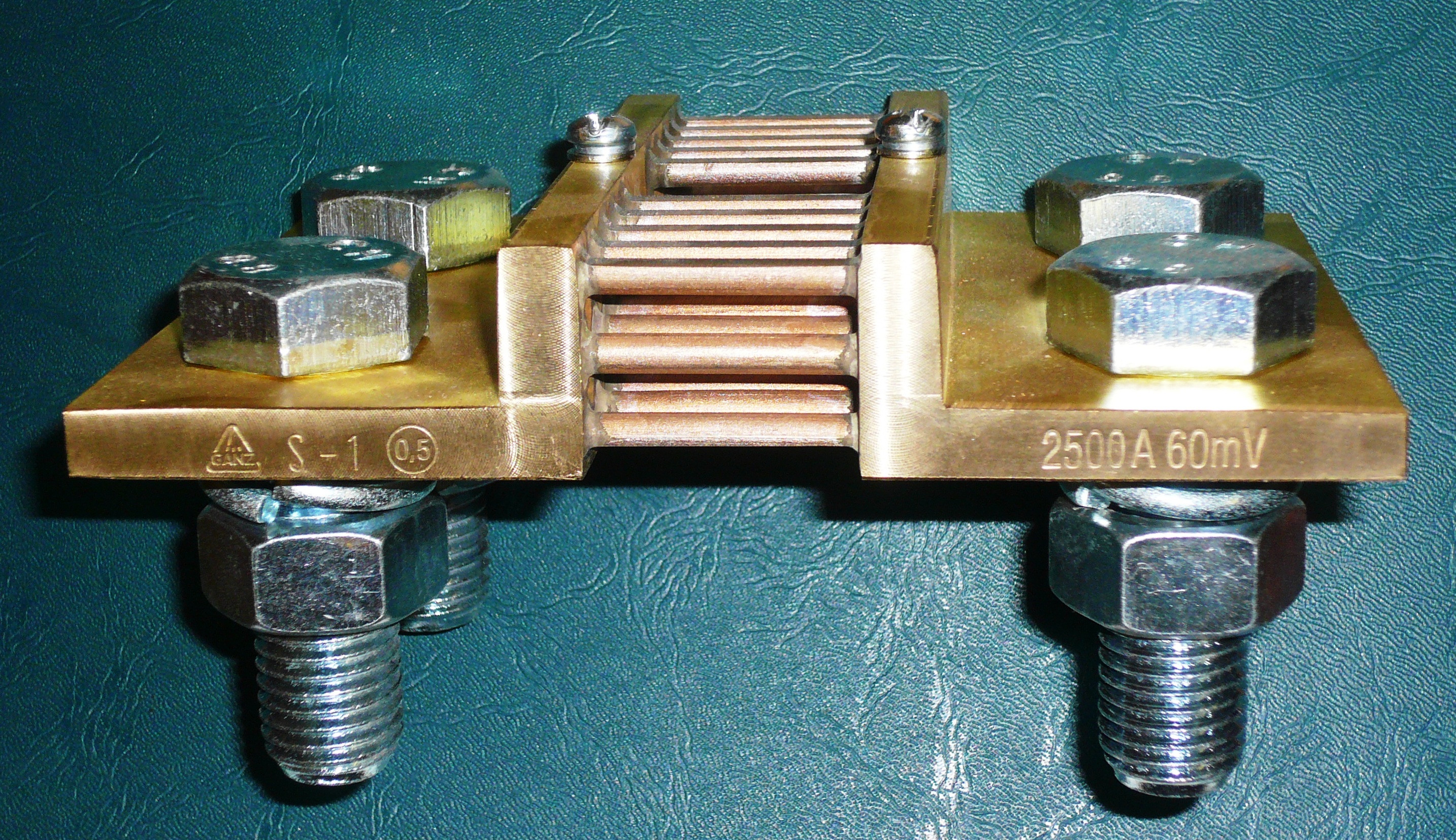
The most instructive specialty resistor is also one of the lowest in value: the current-sense shunt. Its job is to turn a current you cannot measure directly into a voltage you can. You put a small, accurately known resistance in series with the load, let the load current flow through it, and read the voltage it develops; by Ohm’s law that voltage is the current times the resistance, so a millivoltmeter becomes an ammeter. The classic panel shunt is designed to drop a standard voltage at full scale — 50, 60, 75, or 100 millivolts are the traditional values — so that a matching moving-coil meter reads current directly. A shunt marked “2500 A, 60 mV” is simply a resistor of 60 mV / 2500 A = 24 microhms built to carry 2500 amperes without overheating.
That tiny value is the whole problem. A shunt is usually somewhere between a few microhms and a few ohms — for a chip current-sense part on a circuit board, typically 0.2 mΩ to 1 Ω; for a big power shunt, microhms. And the trouble with reading a milliohm is that the wires and solder joints and screw terminals you use to connect to it are themselves worth milliohms. A short length of PCB trace, a soldered lead, a bolted lug — each contributes contact and lead resistance in the single-digit-milliohm range, comparable to or larger than the shunt itself. If you connect to the shunt with two wires and measure across those same two wires, the voltage you read is the drop across the shunt plus the drops across both contacts, and you have no way to separate them. Your carefully calibrated milliohm has been corrupted by resistances you cannot control, that change with temperature, torque, and corrosion.
11.2.1.1 Why a shunt has four terminals
The cure is the four-terminal, or Kelvin, connection, named for William Thomson, Lord Kelvin, who worked out the principle for his low-resistance bridge in the nineteenth century. The idea is to separate the job of carrying the current from the job of sensing the voltage. A four-terminal shunt has two large force (or current) terminals through which the load current enters and leaves, and two separate, smaller sense (or voltage) terminals that tap the voltage across the resistive element alone, connected inboard of the current joints.
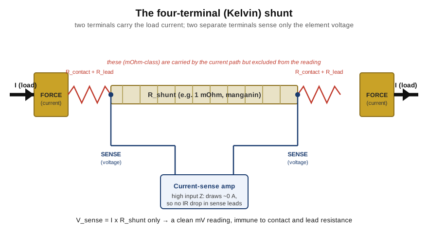
The magic is in what the sense terminals do not carry. The load current flows through the force terminals and their contact resistances, developing whatever drop it develops there — but that drop is outside the sense taps and never appears in the reading. The sense terminals feed a voltmeter or a current-sense amplifier with a very high input impedance, so almost no current flows in the sense path. And with no current in the sense leads, Ohm’s law says there is no IR drop in them either — their resistance, and the resistance of their contacts, becomes irrelevant, because zero amps times any resistance is zero volts. The voltage that reaches the amplifier is therefore the drop across the resistive element and nothing else. A 24 µΩ shunt read through 5 mΩ bolted joints gives an honest 24 µΩ reading, because the joints are in the force path and the measurement is taken in the current-free sense path. This is the single most important idea in low-resistance work, and it recurs in Volume 13 as the four-wire ohmmeter technique for measuring any low resistance on the bench.
11.2.1.2 Reading millivolts honestly: the material matters
Getting the connection right is only half of it. When full scale is 60 millivolts, a few microvolts of error is already a fraction of a percent, and there are two sneaky sources of microvolts to worry about. The first is temperature coefficient. The element carries the full load current and dissipates real power — a 2500 A shunt at 60 mV is dissipating 150 watts — so it runs hot, and if its resistance drifted with temperature the calibration would wander with the load. That is why shunt elements are made not of copper or ordinary resistance wire but of manganin, a copper-manganese-nickel alloy (roughly 84% Cu, 12% Mn, 4% Ni) whose resistance is almost flat with temperature near room conditions — a temperature coefficient of only about ±10 to ±15 ppm/°C, and essentially zero at one design temperature because the curve is a shallow parabola. Its close relative Zeranin does the same job. The second source is thermal EMF: wherever two dissimilar metals meet at different temperatures, a thermocouple voltage appears, and in a millivolt measurement even a microvolt of it matters. Manganin is chosen partly because its thermoelectric voltage against copper is small, a couple of microvolts per degree, keeping that error down. On a circuit board the same reasoning drives the choice of metal-strip or metal-element current-sense chips — a folded strip of low-tempco alloy welded between two copper terminations, in packages from 0.2 mΩ upward, read by a dedicated current-sense amplifier. The engineer picks the shunt value as a compromise: large enough that the sense voltage rises comfortably above the amplifier’s offset and noise, small enough that the I²R power loss and the voltage “burden” it steals from the load stay acceptable.
Where the shunt sits in the circuit is its own small design decision. Put it in the ground return, below the load, and it is low-side sensing — simple, because the sense voltage is referenced near ground and an ordinary amplifier can read it, but at the price of lifting the load’s ground reference off true ground by the shunt drop and hiding any fault current that finds its own path to ground. Put it in the supply line, above the load, and it is high-side sensing — it keeps the load solidly grounded and catches short-to-ground faults, but now the little sense voltage rides on top of the full supply rail, so it needs a current-sense amplifier with a high common-mode range able to extract a few millivolts of difference sitting on tens of volts of common-mode. The same four-terminal element serves either way; only the amplifier around it changes. It is worth adding that the shunt’s honest four-terminal cousin at the top of the accuracy ladder is the metrology standard resistor, a hermetically sealed manganin element with four terminals brought out precisely so that its value can be transferred on a bridge with no contact error at all — the same Kelvin idea taken to the limit, and a part Volume 13 returns to.
11.2.2 High-voltage resistors and dividers
At the opposite extreme from the shunt sits the high-voltage resistor, and here the governing problem is not milliohms but arcing. A resistor’s ceramic or epoxy body has a certain breakdown strength, but the more insidious limit is surface flashover: an arc that tracks along the outside of the body from one end cap to the other, through the air and along any film of dust or moisture on the surface. Two things fight it. First, the body is made long, because flashover voltage rises with the surface distance the arc must bridge, so a resistor rated for tens of kilovolts is a slender rod many centimetres long. Second, the resistive element itself is laid down as a fine spiral of thick film on a ceramic tube (a helically trimmed thick-film track), which both packs a high resistance — values run from megohms up to gigohms — into the body and distributes the voltage gradient smoothly along it.
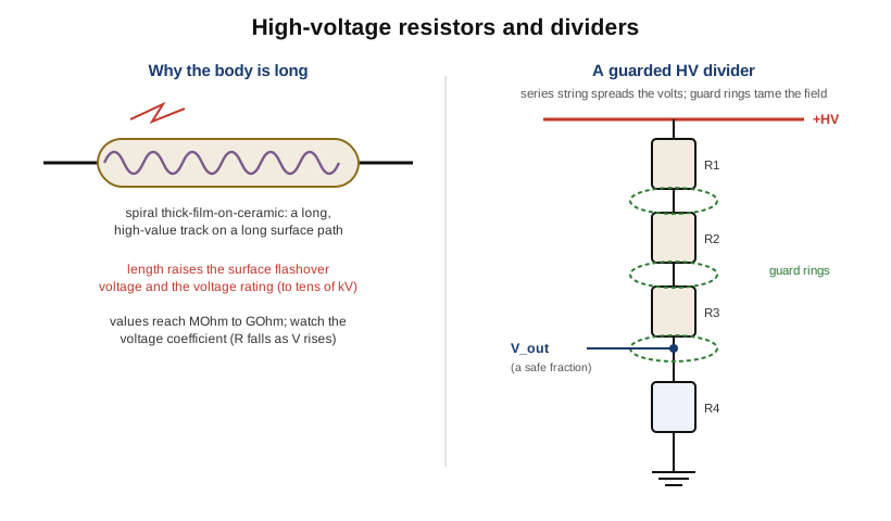
High-voltage parts bring back a non-ideality that the low-voltage volumes could mostly ignore: the voltage coefficient of resistance, the fact that the resistance itself changes slightly with the voltage applied across it, usually falling by tens or a few hundred parts per million per volt in a thick-film element. Over a few volts it is negligible; across ten kilovolts it is a real error, so precision HV resistors are specified with a voltage coefficient and are voltage-derated — run well below their maximum rating so the coefficient, the flashover margin, and the self-heating all stay comfortable.
The canonical high-voltage application is the divider, used to bring a dangerous voltage down to a level an ordinary meter or ADC can read. A single resistor cannot take the whole kilovoltage, so the divider’s high side is a series string of many resistors that shares the voltage across all of them, keeping each element within its own rating. The precision then depends on the ratio of the string to the bottom resistor, and on that ratio holding as temperature and voltage change — which is why HV dividers lean on the matched, tracking behaviour of Volume 10’s networks and on low voltage coefficients. Around the junctions, designers add guard rings and guard traces: conductors held at a controlled potential that flatten the electric field, prevent corona and leakage across the surface, and stop stray currents from sneaking into the measurement node.
11.2.3 High-power and chassis-mount parts, in brief
The high-power resistor — the aluminium-clad “brick” bolted to a heatsink, the vitreous-enamel wirewound tube, the thick-film power pad on an insulated metal substrate — is a specialty in the thermal sense, built to turn tens or hundreds of watts into heat and get that heat out to a chassis without cooking itself. Its physics, its derating curves, and its packages were the whole subject of Volume 9 and are not repeated here; it is enough to note that a chassis-mount power resistor is as much a specialty part as a shunt, defined by the one hard thing it does, which in its case is surviving its own dissipation.
11.2.4 Fusible, flameproof, and safety resistors
Most of this dive treats overload as something to avoid. A small family of resistors treats it as something to handle gracefully, and they are the ones on which product safety often quietly depends. When a fault elsewhere in a circuit dumps far too much power into a resistor, an ordinary part can char, blister, spit burning coating, or crack — and Volume 9’s photograph of a charred film resistor showed exactly that. A flameproof resistor is built and coated so that even when it is destroyed by overload it does not flame, glow, or shower sparks; its coating is a non-combustible cement rather than a lacquer that can ignite.
A fusible resistor goes further and is designed to act as a fuse as well as a resistor. Under normal conditions it is simply a low-value resistor in the circuit; under a sustained overload it is engineered to open cleanly — the element parts, quietly and without flame — breaking the circuit exactly as a fuse would. This dual role is common at a power-supply input, where a few-ohm fusible resistor limits inrush current in normal use and then sacrifices itself to open the line if a downstream component shorts. Because these parts stand between a fault and a fire, they are the ones that carry formal safety approvals and are tested to standards such as UL 1412 and the relevant IEC 60384 and end-product safety norms; a resistor sold as a “safety” or “fusing” resistor is one whose fail-open behaviour has been type-tested, not merely hoped for. The key mental shift is that for these parts the important specification is not the tolerance or the tempco but the failure mode: they are chosen because when they die, they die open and cold.
11.2.5 Non-inductive power resistors
A wirewound resistor is a coil, and a coil is an inductor — a fact that matters whenever a power resistor must handle fast edges or high frequencies, as in a snubber, a dummy load, or a pulse circuit. The standard fix is the Ayrton–Perry winding, in which two windings are run in opposite directions so their magnetic fields cancel and the residual inductance is small. This non-inductive construction was covered in detail in Volume 8; it is flagged here only to place it in the family of specialty parts, because “power resistor that does not ring on a fast edge” is exactly the kind of extreme-job specialty this volume is about.
11.2.6 Zero-ohm jumpers
The strangest entry in the fixed-resistor catalogue is the resistor with no resistance: the zero-ohm jumper. It is a resistor-shaped part — an axial body with a single black band, or a chip marked “0”, “00”, or “000” — that is simply a wire link in a resistor’s clothing. Its reason to exist is manufacturing: a board assembled by an automatic pick-and-place or axial-insertion machine can only place components of a certain shape, so when the layout needs a wire jumper to cross a track or to leave an option open, a zero-ohm “resistor” lets the same machine drop a jumper into a normal resistor footprint. It is not literally zero; it has a small residual resistance, typically tens of milliohms, and — importantly — a current rating, because a thin chip jumper can only carry an amp or two before it overheats, while larger jumpers are rated for more. Treated as a component it is trivial; treated as a wire it is a reminder that the resistor footprint is also the industry’s standard way to place a controlled short.
11.3 Part B — Sensing resistors: the ones built to change
Everything so far has been a fixed value defended against the world. The rest of this volume is about resistors that invite the world in. In each case some physical quantity changes the resistance by a known law, so that reading the resistance reads the quantity: these are resistive transducers. For each family the questions are the same three — what physical quantity moves the resistance, what relation governs the movement, and what it is canonically used for.
11.3.1 Thermistors: resistance that reads temperature
A thermistor — the name compresses “thermal resistor” — is a resistor whose value is a strong, deliberate function of temperature. There are two species, and they behave oppositely.
11.3.1.1 The NTC thermistor
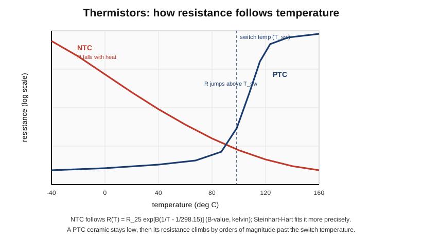
The NTC (negative temperature coefficient) thermistor is the common one. It is a small bead, disc, or chip of sintered metal-oxide ceramic — mixed oxides of manganese, nickel, cobalt, and copper — and its resistance falls as it warms, steeply and smoothly. The fall is not linear but roughly exponential, and to first order it follows the B-value (or β) equation, in which the resistance at temperature T (in kelvin) is the resistance at a reference temperature times an exponential in (1/T − 1/T_ref). The B-value, a material constant usually quoted as B₂₅/₈₅ and typically in the range 3000–4000 K, sets how sharply the resistance drops; a common part might be 10 kΩ at 25 °C with a B of 3950 K. For accurate work over a wide range the simple B-value model is replaced by the Steinhart–Hart equation, a three-coefficient fit (1/T = A + B ln R + C (ln R)³) that tracks the real curve to a few thousandths of a degree. These relations are named here rather than derived; the working point is that an NTC gives a large, repeatable resistance change per degree, which is what makes it a sensitive thermometer.
That sensitivity drives two canonical jobs. The first is temperature sensing and compensation — the NTC is the cheap, rugged thermometer inside battery packs, appliances, engine sensors, and the cold-junction compensation of thermocouple inputs, and it is the element that lets a circuit correct another component’s drift by measuring the temperature they share. The second, which exploits the NTC’s self-heating rather than the ambient, is inrush-current limiting. A power supply switched on into a big reservoir capacitor would draw a huge momentary surge; an NTC placed in series starts cold, where its resistance is high (several ohms to tens of ohms), and so throttles that first surge. Then the load current warms it, its resistance collapses toward a fraction of an ohm, and it stops wasting voltage once the danger has passed. It is a resistor that is large exactly when you need it and small the rest of the time.
11.3.1.2 The PTC thermistor and the resettable fuse
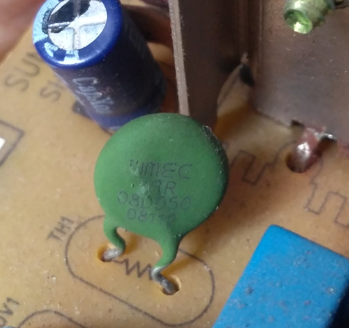
The PTC (positive temperature coefficient) thermistor does the opposite: its resistance rises with temperature — and the useful kind rises not gently but as a near-cliff. The ceramic PTC, based on doped barium titanate (BaTiO₃), stays low and roughly flat until it reaches a switch temperature (tied to the material’s Curie point), above which its resistance jumps by orders of magnitude over a narrow band. That switch makes it a self-regulating device: as a self-limiting heater it settles at its switch temperature and cannot run away, and as a protection element it sits low in normal use but, if an overcurrent heats it past the switch point, snaps to a high resistance and chokes the current off — the mechanism behind the classic degaussing circuit and various motor and overcurrent protectors.
The same principle in a different material gives one of the most useful parts in modern electronics: the polymer PTC, sold as the PPTC, polyfuse, or under trade names such as PolySwitch — the resettable fuse. It is a thin element of polymer loaded with conductive carbon; normally the carbon forms a low-resistance network, but an overcurrent heats the polymer until it expands and breaks the carbon chains, and the resistance shoots up, throttling the current to a tiny trickle. It is specified not by ohms but by a hold current (the current it passes indefinitely) and a trip current (the current at which it snaps high). The beauty is that it resets: remove the fault, let it cool, the carbon network reforms, and the part conducts again — a fuse you never have to replace, guarding USB ports, battery packs, and countless consumer boards.
11.3.1.3 Thermistor versus RTD
A thermistor is easy to confuse with the other resistive thermometer, the RTD (resistance temperature detector), so the distinction is worth stating plainly. An RTD is a coil or film of a pure metal — almost always platinum, as in the Pt100 (100 Ω at 0 °C) and Pt1000 — and it relies on the mild, clean, positive temperature coefficient of a pure metal, about +3850 ppm/°C for platinum, giving a resistance that rises nearly linearly with temperature. The trade is sensitivity for linearity and range. A thermistor changes resistance enormously per degree but only over a modest, curved span; a Pt100 changes little per degree but does so almost linearly from below −200 °C to above +600 °C, with excellent long-term stability. So the rule of thumb is: reach for a thermistor when you want cheap, sensitive sensing over a limited range, and for an RTD (Pt100/Pt1000, to the IEC 60751 standard) when you want accuracy, linearity, and wide range — and note that a precision RTD is itself usually read with the same four-wire Kelvin connection the shunt taught us, because its lead resistance would otherwise add to its hundred-odd ohms.
11.3.2 Varistors: a resistor that watches the voltage
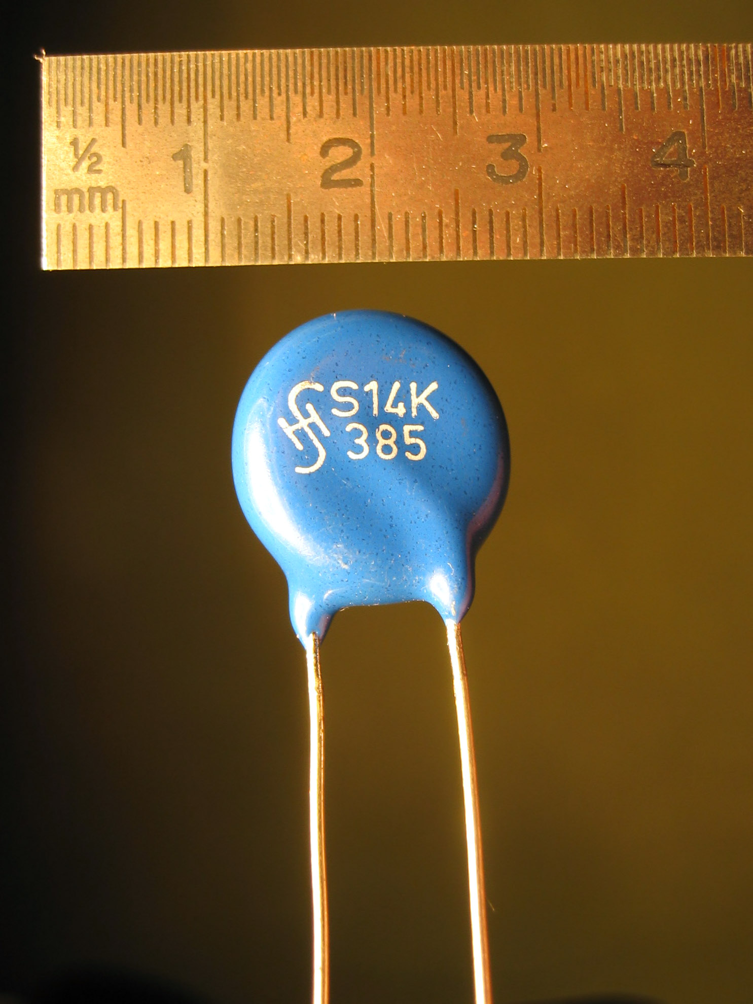
The varistor — from variable resistor, though it has nothing to do with a potentiometer — is a resistor whose resistance depends on the voltage across it. At low voltage it is a very high resistance, nearly an open circuit; above a characteristic varistor voltage its resistance collapses and it conducts hard. The dominant type is the metal-oxide varistor, or MOV, a sintered disc of zinc oxide grains whose boundaries act like a vast array of back-to-back semiconductor junctions. Because those junctions are symmetric, the device behaves the same for either polarity, giving the characteristic symmetric, highly non-linear V–I curve.
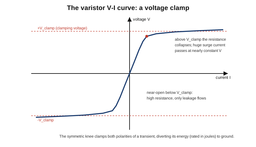
That curve is the whole point. Wired across a supply — most often straight across the AC mains, line to neutral — a varistor does nothing in normal operation, presenting a near-open circuit and drawing only microamps of leakage. But when a transient arrives — a lightning-induced spike, a switching surge, the kick from a motor turning off — the voltage shoots above the clamping level, the MOV’s resistance collapses, and it conducts a large surge current while holding the voltage down to its clamping voltage. In effect it swallows the surge’s energy, converting it briefly to heat in the ceramic and shunting it away from the delicate circuit downstream. An MOV is therefore rated by three numbers the specialty resistors never needed: its varistor voltage (commonly measured at 1 mA), its clamping voltage at a defined surge current, and its energy rating in joules together with a peak surge current for a standard pulse shape (the 8/20 µs waveform). It has one wearing-out failure mode worth respecting: every surge it absorbs degrades the zinc-oxide junctions a little, its leakage creeps up and its varistor voltage drifts down over many strikes or one very large one, and a badly overstressed MOV can end its life short-circuited and hot — which is why serious surge protectors pair the MOV with a thermal cutout.
11.3.3 Photoresistors: resistance in the dark
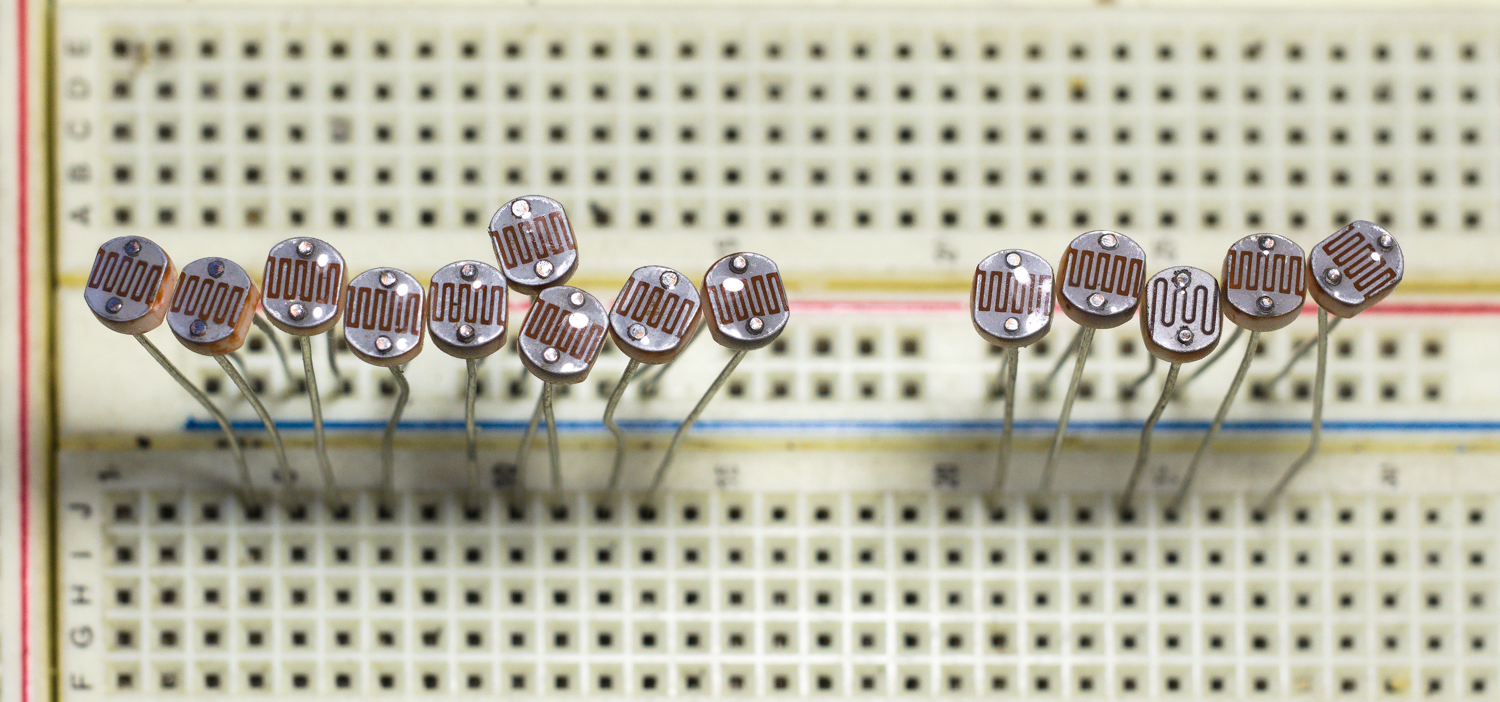
The photoresistor, or light-dependent resistor (LDR), is a resistor whose value depends on the light falling on it. It is a film of a photoconductive semiconductor — classically cadmium sulphide (CdS), sometimes cadmium selenide — laid in a serpentine track between two electrodes. In the dark, few charge carriers are free and the resistance is high, often a megohm or more; light photons free carriers and the resistance drops, to a few hundred ohms or kilohms in bright illumination. It is the simplest possible light sensor: two terminals, no bias polarity, no supporting circuit beyond a series resistor to make a voltage divider.
Its limitations are as characteristic as its simplicity. An LDR is slow, taking milliseconds to respond and showing a “memory” that depends on its recent light history, and its response is non-linear and varies part to part, so it is a device for detecting light levels — dusk, shadow, presence — rather than measuring them precisely. The larger issue today is chemical: cadmium is a restricted heavy metal under the RoHS directive, and although CdS cells have long enjoyed exemptions, the restriction has steadily pushed new designs toward photodiodes and phototransistors, which are faster, more linear, and cadmium-free. The classic CdS cell survives in the cheapest, least critical light sensing — night-lights, dusk switches, camera metering of the simplest kind — but it is a sunset technology, and the design instinct now is to reach for a photodiode unless the application is trivial.
11.3.4 Strain gauges: resistance under load
The last and in some ways most elegant sensing resistor is the strain gauge, a resistor whose value changes with mechanical strain — with how much the material it is bonded to is stretched or compressed. It is a fine grid of resistive foil, usually the alloy constantan, photo-etched into a long back-and-forth pattern on a thin flexible backing that is glued firmly to the surface under test. When the surface stretches, the foil stretches with it: it gets slightly longer and slightly thinner, and both changes raise its resistance; when the surface is compressed, the resistance falls. Strain is a tiny fractional change in length, so the resistance changes are tiny too, but they are real and repeatable.
The relation is captured by a single number, the gauge factor (GF), defined so that the fractional change in resistance equals the gauge factor times the strain: ΔR/R = GF × ε. For ordinary metal-foil gauges the gauge factor is close to 2.0 (constantan is a touch over two), which means a strain of one part in a thousand — a large strain for metal — changes the resistance by only about two parts in a thousand. Typical gauges are made in convenient values such as 120 Ω, 350 Ω, or 1000 Ω. (Silicon piezoresistive gauges reach gauge factors of a hundred or more, far more sensitive, but at the cost of temperature sensitivity and fragility; the metal foil gauge remains the workhorse of general mechanical measurement.)
A resistance change of a fraction of a percent is far too small to read with an ordinary ohmmeter, and this is where the strain gauge closes the circle back to the start of the volume: it is read in a Wheatstone bridge. Four resistances are arranged in a diamond, excited by a voltage across one diagonal, and the imbalance is read across the other. When all four are equal the bridge is balanced and the output is zero; a small change in one arm unbalances it and produces a small differential output proportional to that change, which an instrumentation amplifier can amplify from microvolts to a usable signal. In a quarter bridge one arm is the active gauge and the other three are fixed, giving an output of roughly (V_excitation / 4) × (ΔR/R). A half bridge makes two arms active — often one in tension and one in compression — to double the output and cancel temperature effects, and a full bridge makes all four active for the largest, cleanest, most temperature-stable signal.
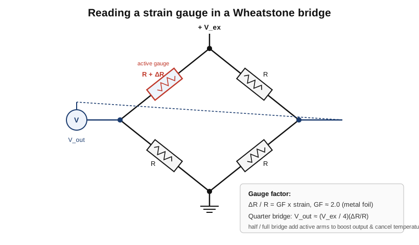
This bridge-read strain gauge is the heart of an enormous class of sensors. Bond gauges to a carefully machined metal spring element — a beam or a proving ring — and you have a load cell, the transducer inside every electronic scale and force gauge, turning weight into a millivolt signal. Bond them to a diaphragm and you have a pressure sensor. The strain gauge is where a resistor stops being a component and becomes an instrument.
11.4 From passive component to sensor
The parts in this volume mark the far edge of what a resistor can be. On one side sit the specialty fixed resistors — the shunt, the high-voltage divider, the fusible and flameproof safety part, the non-inductive power resistor, the zero-ohm jumper — each an ordinary idea, resistance, pushed to an extreme of value, voltage, or fault behaviour, and each teaching a lesson the everyday resistor could hide: that a milliohm needs four terminals to be read honestly, that a kilovolt needs length and guard rings, that a safety-critical part is defined by how it fails. On the other side sit the transducers — the thermistor, the varistor, the photoresistor, the strain gauge — resistors engineered to abandon constancy and let temperature, voltage, light, and strain reach in and move their value by a known law, so that measuring the resistance measures the world.
That second group is the bridge from this dive’s subject to the next field over. A thermistor is a thermometer, a strain gauge is the core of a scale, an MOV is a surge protector, an LDR is a light sensor: they are the point where the passive component becomes a sensor. And notice how they are read. The shunt and the RTD lean on the four-wire Kelvin connection to keep lead resistance out of a small reading; the strain gauge lives inside a Wheatstone bridge to pull a fractional part-per-thousand change out of the noise. Those two circuits — Kelvin’s four-terminal method and Wheatstone’s bridge — are the measurement techniques that make low resistances and tiny resistance changes readable at all, and they are the subject of Volume 13, where the same ideas that let a shunt report 2500 amperes and a foil grid report a gram of weight are turned into the bench methods for measuring any resistor, from a microhm to a teraohm.
Comments (0)