Resistors · Volume 7
Fixed Types I: Carbon Composition and Film Resistors
7.1 A map of the fixed-resistor family
Every earlier volume treated the resistor in the abstract — a number of ohms, held to a tolerance, drifting by so many parts per million with temperature, hissing with a certain noise. This volume and the next are where those abstractions acquire a body. A designer reaching into a parts drawer does not pick “a resistor”; they pick a carbon-film 1 kΩ 5% or a metal-film 4.99 kΩ 0.1% or a metal-oxide 100 Ω flameproof, and the words before the value are a compressed forecast of how the part will behave. Learning to read those words is the whole point of the two “fixed types” volumes. This one, Volume 7, covers the four types built by molding a slug of carbon or by depositing a thin film on a ceramic rod: carbon composition, carbon film, metal film, and metal-oxide film. Volume 8 takes the extremes — wirewound for power and metrology, bulk metal foil for the last decade of stability, and the thick- and thin-film chip that dominate surface-mount boards.
It helps to see the whole family on one page before diving into any branch. Strip the catalogue down and there are only three ways to make the resistive element, plus one precision outlier. Bulk (composition) parts carry their resistance in the whole volume of a molded body — a slug of carbon granules in a binder, with the current crossing the entire cross-section. Film parts carry it in a thin skin on an insulating carrier: a layer of carbon, a nickel-chromium alloy, a metal oxide, or a fired paste, sitting on a ceramic rod or a flat alumina chip. Wirewound parts wind resistance wire on a core, from heavy nichrome for power to hair-fine manganin for a laboratory standard. And bulk metal foil — the outlier — photo-etches a rolled alloy foil bonded to a substrate, and is reserved for parts that must not move. The four types in this volume are the whole of the bulk branch and the axial-rod part of the film branch; the chip-film and wire branches wait for Volume 8.
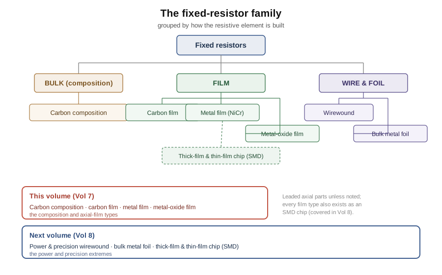
Two orthogonal splits cut across that tree and are worth naming, because catalogues sort by them. The first is leaded versus surface-mount: an axial part has a wire lead out of each end for through-hole assembly, while a chip is a leadless block with metallised ends that solders flat to a pad. This volume is almost entirely about leaded axial parts, since composition and axial film are the leaded world; the chip forms of the same films belong to Volume 8. The second split is bulk versus surface, and it is the one that decides character. In a bulk part the resistive material is thick and there is a lot of it, so it soaks up a fault energy without any single thin layer reaching a fatal temperature. In a film part the working material is a skin a fraction of a micron to a few microns thick, so it is cheap, precise, and easy to trim — but a large enough pulse can heat that skin to destruction faster than the ceramic underneath can carry the heat away. That single contrast explains most of what follows: why the crudest, oldest type refuses to die in surge roles, and why the precise modern film that replaced it everywhere else is, paradoxically, the more fragile part under abuse.
7.2 Carbon composition: the ancestor that will not leave
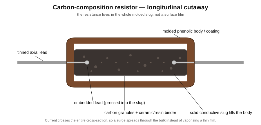
The carbon-composition resistor is the oldest survivor in the drawer, and understanding it first makes every later type read as a reaction against its faults. Its construction is almost aggressively simple. A finely ground carbon (graphite or lampblack) is mixed with an inert filler and a binder — historically a ceramic clay, later a thermosetting resin such as phenolic — into a dough whose carbon fraction sets the bulk resistivity. The higher the carbon content, the more conductive the mix; a dilute mix gives a high-ohm part, a carbon-rich mix a low-ohm one. Two wire leads are pushed into the ends of the dough, and the whole thing is molded under heat and pressure into a small cylinder and cured hard. A coat of phenolic or lacquer seals it and carries the color bands. The result is a solid rod of weakly conducting material with a lead buried in each end, and the current flows through the entire body from one lead to the other.
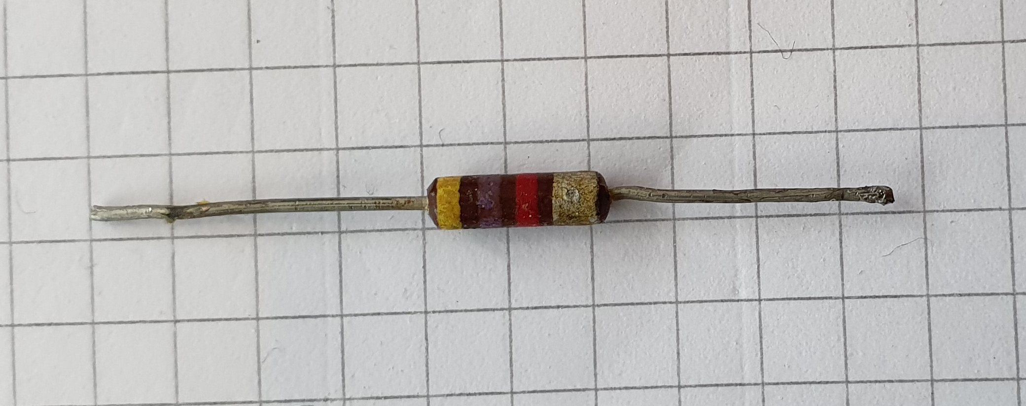
For roughly the first half of the twentieth century this was simply what a resistor was. From the 1930s through the vacuum-tube age and into early transistor equipment, the hot-molded carbon-composition resistor — Allen-Bradley’s being the archetype — was the default component of the entire electronics industry, made by the billion because it was cheap, small, rugged, and needed no precision to manufacture. A radio, a television, an early computer, a piece of military gear: open any of them from that era and the little brown-banded cylinders are everywhere. The type’s dominance was not a matter of merit so much as of there being nothing better that was equally cheap; when something better arrived, the composition part collapsed out of the mainstream within about two decades.
It is worth being honest about why it was displaced, because the ledger of vices is long. Start with tolerance: composition parts are typically ±5% at best, and ±10% and ±20% grades were and are common. There is no way to trim a molded slug after the fact — the value is whatever the carbon fraction and the geometry produced — so the spread is wide. Next, temperature coefficient: it is large, and worse, it is non-linear and non-monotonic. A composition resistor’s resistance falls a little as it warms from room temperature, reaches a minimum, then climbs, and over the full range the excursion runs to hundreds and even something on the order of a thousand or more parts per million per degree — an order of magnitude worse than a film part, and not in a straight line you can compensate. Then voltage coefficient (VCR): the resistance of a carbon slug depends measurably on the voltage gradient across it, so the “same” resistor reads a different value at 5 V than at 500 V. This is a genuine source of distortion in a signal path, because a resistance that varies with the instantaneous voltage across it turns a pure sine wave into one with harmonics.
The list continues. Excess noise — the low-frequency, current-dependent noise that rides on top of the unavoidable thermal (Johnson) floor and rises as 1/f — is worst of all in carbon composition, because the current threads through a mass of loosely touching carbon grains whose contact resistances fluctuate. A composition part can have an excess-noise index orders of magnitude higher than a metal film of the same value, which matters in the first stage of a microphone preamp or any high-gain low-level circuit. Finally there is environmental instability: the porous molded body absorbs moisture, so humidity shifts the value, and the part drifts with age and with soldering heat, sometimes permanently by a few percent after a hard reflow. A composition resistor pulled from a fifty-year-old radio has very often drifted high, and measuring a batch of them is an education in how far “±10%” can wander once decades of moisture and thermal cycling are added.
Against that catalogue of sins stands one real virtue, and it is the reason the type is still manufactured and still specified today: single-pulse and surge energy handling. Because the resistance lives in the bulk of a solid slug rather than in a micron-thin film, a large transient — a lightning-induced surge, a capacitor-discharge dump, an electrostatic-discharge strike, a strobe or welding pulse — spreads its energy through the whole cross-section of carbon. There is no thin layer to reach a vaporising temperature at a hot spot; the mass and the distributed conduction let the part absorb a joule-scale pulse that would blow a film resistor open. The same geometry makes it essentially non-inductive: there is no helical trim groove forcing the current into a coil, so the parasitic inductance is very low, which matters at radio and pulse frequencies. For these reasons manufacturers such as Ohmite and Vishay still list carbon-composition parts explicitly for surge, ESD, high-voltage, and pulse duty, and datasheets often quote a single-pulse energy or a peak-voltage rating that a comparable film part cannot approach. It is a component kept alive by exactly one of its properties.
The physics behind the surge virtue is worth stating plainly, because it is the whole justification for keeping such a flawed part in production. When a resistor absorbs a pulse, the energy goes first into heating the resistive material itself before any of it can flow out into the leads or the surrounding air; what matters in the first microseconds to milliseconds is the energy density in the material — joules per unit volume — and the temperature that density produces. A thin film concentrates the whole pulse into a layer perhaps a micron thick, so even a modest energy raises that sliver to a destructive temperature and the film opens at its hottest point. A bulk carbon slug spreads the same energy through a body thousands of times thicker, so the peak temperature rise is far smaller and the part survives. This is not a subtle margin: a composition resistor can routinely absorb a single pulse tens or hundreds of times larger than a film part of the same physical size and rating. Everything else about the type is a liability, but this one property is a direct, unavoidable consequence of putting the resistance in the bulk, and no amount of film refinement can match it.
A few practical numbers frame where the type actually appears. Carbon-composition parts are made in the ordinary axial power sizes — nominally quarter-, half-, one-, and two-watt bodies — and cover a value range from a few ohms up into the tens of megohms, with the very low and very high ends both harder to hold than a mid-range value. The catalogue makers are no longer the giants that once stamped them out by the billion: Allen-Bradley, the historic archetype, left the business decades ago, and today the parts come from a shorter list of specialists — Ohmite (its OW/OX/OY axial series), Vishay through the former Cornell-Dubilier/CGW line, and a handful of others such as Nikkohm — precisely because the remaining demand is the surge and pulse niche rather than volume manufacturing. When a modern datasheet lists a carbon-composition part it almost always leads with the single-pulse energy, the peak working voltage, and the non-inductive construction, and treats the loose tolerance and tempco as the price of admission — an inversion of how every other resistor is sold, and a fair summary of why the type still exists at all.
That niche, and a certain nostalgia, feed a persistent claim worth examining skeptically: that carbon-composition resistors “sound better” in audio equipment, particularly in guitar amplifiers and vintage-style hi-fi. The engineering reading is unsentimental. A composition resistor does measurably alter a signal — but by adding things a good resistor should not: its voltage coefficient introduces harmonic distortion, its high excess noise adds a hiss and crackle floor, and its drift and tempco make the operating point wander. In a guitar amplifier, where distortion and a particular noise character are part of the desired sound, some builders genuinely prefer that coloration, and that is a legitimate aesthetic choice — but it is a choice for more distortion and more noise, not for some hidden fidelity the measurements miss. In a circuit where accuracy and transparency are the goal, the composition part is strictly worse, and blind listening tests have never supported a fidelity advantage. The honest summary is that carbon composition can change the sound, and if that particular change is wanted it can be the right part; it never makes the signal cleaner. Reaching for it as a general-purpose upgrade is reaching backward.
7.3 Carbon film: the cheap workhorse that fixed the worst of it
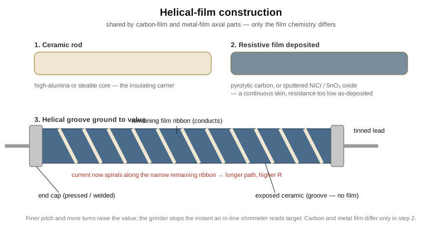
If carbon composition is the ancestor, carbon film is the first reform. It keeps carbon as the conducting material but abandons the bulk slug for a thin film on a ceramic rod, and that one change repairs several of the composition part’s worst faults at almost no extra cost. The film is laid down by pyrolytic deposition: a high-purity ceramic rod is heated in an atmosphere of a hydrocarbon gas such as methane or benzene vapor, and at red heat the gas cracks — pyrolyzes — into hydrogen, which leaves, and carbon, which deposits as a hard, adherent, graphitic skin a fraction of a micron to a few microns thick over the rod. The thickness and the deposition time set the film’s sheet resistance; the rod’s diameter and length then fix the as-deposited value, which is always made deliberately too low so it can be trimmed up.
Trimming is where the value is actually set, and it is mechanical. A grinding wheel or diamond cutter cuts a helical groove through the film, spiraling down the rod like the thread of a screw. Removing that ribbon of carbon does two things at once: it forces the current to travel a long spiral path instead of straight down the rod, and it narrows the conducting track that remains — both raise the resistance. A rod that started at a few hundred ohms can be trimmed to tens of kilohms by cutting more turns of finer pitch, while an in-line ohmmeter watches the value and stops the grinder the instant the target arrives. End caps are pressed onto the ends, leads are welded to the caps, and a lacquer coat — usually beige or tan, the field mark of a carbon-film part — seals it and carries the bands. This helical construction is not unique to carbon film; the metal-film part in the next section is built in exactly the same way, differing only in what the film is made of.
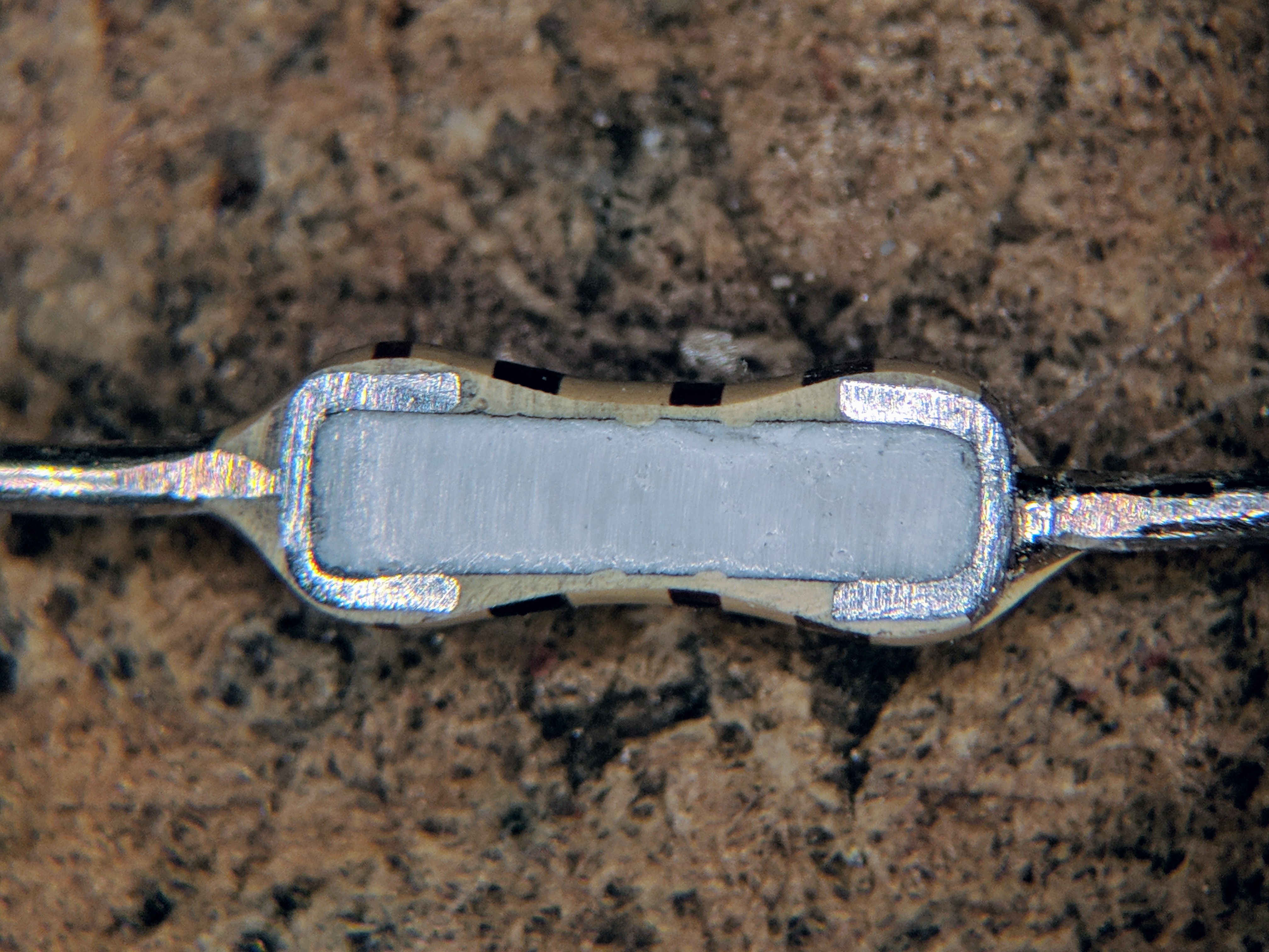
The electrical payoff over composition is real if modest. Tolerance improves to roughly ±2–5%, because the helical trim lets each part be brought to value individually rather than left wherever the molding landed; the standard consumer carbon-film part is a ±5% E24-value component. The temperature coefficient becomes negative and reasonably well-behaved — graphitic carbon has a negative tempco, so a carbon-film resistance falls as it warms, roughly in the range of −200 to −500 ppm/°C depending on grade and value. That is still several times worse than a metal film and of the “wrong” sign for compensating a positive-tempco circuit, but it is a smooth, monotonic, single-figure coefficient instead of composition’s wandering excursion. Excess noise drops too, because a continuous film has far fewer fluctuating grain-to-grain contacts than a slug of pressed powder, though carbon film is still noticeably noisier than any metal film. Voltage coefficient and moisture sensitivity both improve. None of these is best-in-class, but every one is better than composition, and the part costs no more to make.
The negative temperature coefficient deserves a second look, because it is occasionally a feature rather than a flaw. A carbon-film resistance falls as it heats, and there are circuits — a bias network feeding a bipolar transistor, whose base-emitter drop itself falls with temperature; or a network paired with a positive-tempco component — where a controlled negative tempco partially cancels a drift that would otherwise have to be trimmed out. Designers rarely choose carbon film for its tempco, since the coefficient is neither tight nor well controlled part to part, but where a rough negative slope helps rather than hurts, it is a small bonus that metal film cannot offer. In the ordinary axial sizes — the ubiquitous quarter- and half-watt bodies, with one- and two-watt parts for more dissipation — carbon film covers roughly single ohms to tens of megohms, and like every helical-film part it grows slightly inductive at the high-value end where the trim cuts many fine turns, a detail that only matters at radio frequencies.
Carbon film was, in consequence, the great cost workhorse of the 1970s through the 1990s. As pyrolytic deposition and helical trimming matured, the carbon-film part became the cheapest way to make a resistor good enough for the vast middle of electronics, and it pushed carbon composition out of everything except the surge niche. For a couple of decades a “resistor,” unqualified, in a consumer product very likely meant a beige quarter-watt ±5% carbon film. Where does it still live today? In the price-driven tail: mass-market consumer goods, toys, lighting, power-supply auxiliaries, and any pull-up, current-limit, or bias role where ±5% is plenty and a fraction of a cent per part matters more than a tempco specification. It has since been squeezed from the other side by the thick-film SMD chip on boards that went surface-mount, and even in the leaded world by metal film as precision parts got cheap — but as a leaded, low-cost, non-critical resistor it remains entirely current.
7.4 Metal film: the modern default for anything precise
Metal film is the type most engineers now mean when they say “a 1% resistor,” and it earned that default status by being better than carbon film on every axis that matters while costing only a little more. The construction is the helical-film process again, with one crucial substitution: instead of pyrolytic carbon, a thin film of a nickel-chromium (nichrome) alloy — sometimes with additions, sometimes a related metal or a metal-oxide-doped alloy — is deposited on the ceramic rod, usually by vacuum evaporation or sputtering rather than gas cracking. The metal film is then helically trimmed to value exactly as the carbon film is, end-capped, leaded, and coated. The coat is very often blue (sometimes tan, green, or grey by manufacturer), and a blue axial body with a five-band code is the near-universal field mark of a metal-film part.

The reason metal film became the standard is that a thin metallic film is a far better resistive material than either carbon form. Its temperature coefficient is low and, for a metal, naturally small in magnitude — commodity metal film runs 50–100 ppm/°C, and better grades are specified at 25 ppm/°C or tighter, roughly five to ten times steadier than carbon film and orders of magnitude better than composition. Nichrome is chosen partly because its resistivity barely moves with temperature, the same property that makes it a heating-element alloy. Tolerance is where metal film really separates itself: the helical trim of a smooth, uniform metal film can hold ±1% routinely and ±0.1% in precision grades, which is why the standard metal-film part is a ±1% component on the E96 value series — 96 values per decade, enough that almost any nominal you compute has a stock part within 1% of it. Excess noise is very low, because a continuous crystalline metal film has essentially none of the grain-contact fluctuation of pressed carbon; the part sits close to its thermal-noise floor. Voltage coefficient is negligible for the same reason — a metal’s resistance does not depend on the field across it — so metal film introduces essentially no distortion, which is why it is the resistor of choice in precision analog and audio signal paths where composition’s coloration is a defect rather than a feature.
Two details of the standard metal-film part are worth pinning down because they trip up newcomers. The first is the marking. A ±1% metal-film resistor normally carries five bands rather than the four of a ±5% carbon part — three significant-figure bands, a multiplier, and a tolerance band — because holding three significant figures is the whole point of an E96 value like 4.99 kΩ or 1.21 kΩ, and two digits could not express them. Precision grades add a sixth band for the temperature coefficient itself, encoding the ppm/°C class in colour. The second is why the values run on E96 rather than the E24 series of the cheaper parts. The E-series are geometric: each has a fixed number of values per decade spaced so that adjacent values differ by roughly the tolerance, so that the tolerance bands of neighbouring values just meet and the whole number line is covered without wasteful overlap. A ±5% part only needs 24 values per decade (E24) to tile the line at that width; a ±1% part needs 96 (E96) to tile it at the narrower ±1% width. Metal film is stocked on E96 because that is the value set its tolerance earns — the tighter the part, the denser the grid of standard values it justifies. (The E-series construction is treated in full in the volume on reading resistors.)
Long-term stability is the other quiet virtue that keeps metal film in precision work. Beyond its low tempco, a good metal-film part drifts very little with time and load — a typical specification is a change of only a fraction of a percent, often well under ±0.5%, over a thousand hours at rated power and after moisture and soldering stress, an order of magnitude steadier than a composition part that can shift several percent over its life. That combination — tight initial tolerance, low tempco, low noise, negligible voltage coefficient, and small long-term drift — is why a metal-film resistor placed in a gain-setting or reference divider can be trusted to still define the same ratio years later, and why the type displaced carbon composition and carbon film from every role where the value has to mean something.
The practical upshot is that metal film is the correct default answer for “which fixed resistor?” across almost the entire span of general-purpose and precision electronics below the power and metrology extremes. If a design needs a leaded resistor and there is no specific reason to choose otherwise — no kilowatt of dissipation, no need for a ±0.01% laboratory part, no surge pulse to swallow — a metal-film ±1% E96 part is what belongs there, and it is now cheap enough that many designers use it even where ±5% would do, simply to standardise on one drawer of parts. It reads temperature-stable, quiet, and accurate, marks itself with a familiar blue body and five bands, and asks very little in return. The only things it is not good at are the two ends of the range: it does not run hot gracefully, and it does not take a big pulse — which is exactly the gap the last type in this volume fills.
7.5 Metal-oxide film: the film that runs hot and takes a hit
Metal-oxide film is the odd sibling of the film family — built like the others, but chosen for temperature and ruggedness rather than precision. The resistive layer is a tin-oxide (SnO₂) film, deposited on a ceramic rod, usually by a hydrolytic or spray process in which a tin compound is oxidised onto the hot ceramic to leave a hard, adherent oxide skin, sometimes with antimony or other dopants to set the sheet resistance. The film is trimmed and finished much like carbon and metal film, but the finished part is typically a little larger and heavier, and its coat is usually a buff, cream, or grey ceramic-loaded paint rather than the neat blue of metal film — the appearance of a part meant to shed heat.
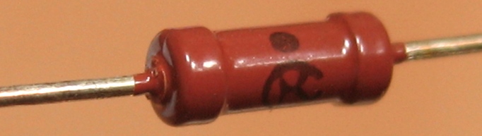
What tin oxide buys is high-temperature operation. The oxide film is chemically and thermally far more robust than a graphitic carbon film or even a nichrome film: it does not oxidise further, does not soften, and holds its resistance at surface temperatures that would degrade the other films. In practice this shows up as much higher permitted body and hot-spot temperatures — standard metal-oxide power grades are commonly rated to a maximum body/surface temperature on the order of 200–235 °C, well above the roughly 155 °C ceiling of a typical carbon- or metal-film part, and the tin-oxide chemistry itself tolerates still higher film temperatures, which is precisely why it is chosen. Because the part is allowed to run hotter, a metal-oxide resistor of a given size can dissipate more steady power than a metal-film part of the same dimensions, and it can absorb larger pulse and surge energies without the film failing — not to the degree of a bulk composition slug, but far better than metal film. Many metal-oxide parts are additionally sold as flameproof grades, with coatings and constructions certified (for example to UL 94 V-0) not to burst into flame under a sustained overload but instead to fail safely, open or smoldering, which is why they are so common as the input or fusible resistor in a mains power supply — the part deliberately placed where a fault will hit first.
The power story is worth making concrete, because “runs hotter” translates directly into “dissipates more.” A resistor’s steady power rating is set by how hot its hottest point is allowed to get for a given way of shedding heat; raise the permitted temperature and the same body can pass more watts before it reaches that limit. So a metal-oxide part in a common axial size is routinely rated at one, two, or three watts where a metal-film part of the same dimensions might be rated a fraction of that, and metal-oxide fills the band between ordinary signal-level film and true power wirewound — roughly the one-to-a-few-watt range where a metal film is already too hot and a wirewound is larger, more inductive, and more expensive than the job needs. Like every resistor it must still be derated above a rated ambient (typically from around 70 °C the allowed power falls linearly to zero at the maximum body temperature), a slope covered in detail in the power-and-derating volume; the point here is simply that the higher end-of-slope temperature is what buys metal-oxide its extra watts.
The price of all that ruggedness is precision. Metal-oxide film has a loose, positive temperature coefficient, typically around ±300 ppm/°C — comparable to or worse than carbon film in magnitude, and much worse than metal film — and its tolerance is usually ±1% to ±5% rather than the tight grades metal film reaches. Its excess noise and voltage coefficient are moderate, better than carbon composition but not in the class of metal film. So a designer does not reach for metal oxide to hold a value accurately; they reach for it when a film part must survive heat or a surge that would kill a metal film — a power-supply surge or bleeder resistor, a snubber, an inrush limiter, a resistor mounted where the ambient runs high, or a safety part specified to fail without flame. It occupies the rung between ordinary film and true power wirewound: hotter and tougher than metal film, still small and cheap and leaded, but never the choice when the ohms have to stay put.
7.6 Choosing among the four
Set the four side by side and a clean decision tree emerges. The matrix below rates them across the properties that actually drive a selection — tolerance, the sign and magnitude of the temperature coefficient, excess noise, voltage coefficient, the maximum body temperature, pulse and surge handling, relative cost, and the value series each is normally stocked on — using the same good-to-poor shading the earlier volumes used, and drawing its figures from Vishay, Yageo, KOA, and Panasonic literature as representative ranges rather than guaranteed limits.
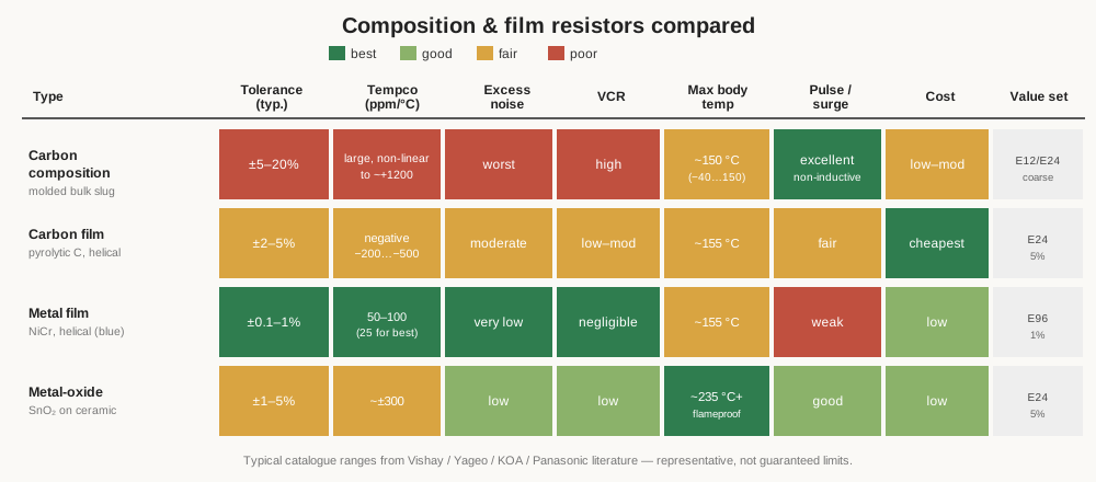
Because a table is easier to scan than prose when a decision is at hand, the same comparison in words and numbers:
Table 1 — words and numbers
| Property | Carbon composition | Carbon film | Metal film | Metal-oxide film |
|---|---|---|---|---|
| Element | molded bulk carbon slug | pyrolytic carbon film | nichrome (NiCr) film | tin-oxide (SnO₂) film |
| Tolerance (typ.) | ±5–20% | ±2–5% | ±0.1–1% (E96) | ±1–5% |
| Tempco | large, non-linear, to ~+1200 ppm/°C | −200 to −500 ppm/°C | 50–100 ppm/°C (25 for best grades) | ~±300 ppm/°C |
| Excess (1/f) noise | worst | moderate | very low | low |
| Voltage coefficient | high | low–moderate | negligible | low |
| Max body temp | ~150 °C | ~155 °C | ~155 °C | ~200–235 °C+ (flameproof grades) |
| Pulse / surge energy | excellent (bulk, non-inductive) | fair | weak | good |
| Relative cost | low–moderate | cheapest | low | low |
| Typical use | surge / ESD / HV / pulse; vintage & guitar | mass-market, non-critical | precision default, analog signal | hot / high-power / flameproof, PSU input |
The reading is straightforward once the properties are laid out. Metal film wins every electrical contest — tolerance, tempco, noise, voltage coefficient — and so it is the default whenever a design simply needs an accurate, quiet, stable resistor, which is most of the time. Carbon film wins only on price, and survives in the cost-driven tail where ±5% is fine and a fraction of a cent matters. Metal-oxide wins on heat and surge, the part to reach for when a film resistor must run hot, take a pulse, or fail safely, at the cost of a loose tempco. Carbon composition wins on exactly two things — raw single-pulse energy and low inductance — and is otherwise the worst of the four, kept in production for surge, ESD, high-voltage, and pulse duty (and bought by some for the coloration it adds to a guitar amplifier, which is a choice for distortion, not fidelity).
A few worked calls make the tree concrete. A pull-up on a logic line, where the exact value is irrelevant and only “some tens of kilohms” is needed: carbon film, ±5%, cheapest part that works. The two gain-setting resistors around an op-amp, where the ratio sets a precise gain and must not drift: metal film, ±1% or tighter on E96, matched values if the gain must be exact. The bleeder resistor across a power-supply filter capacitor, dumping stored energy and running warm for its whole life, ideally failing safe if the supply faults: metal-oxide, flameproof grade, sized for the dissipation. The series resistor in the front of an electrostatic-discharge or surge-protection network, expected to swallow a joule-scale strike without opening: carbon composition, chosen for the one thing it does better than anything else its size. And the input resistor of a low-level microphone preamp, where every microvolt of added noise is audible: metal film again, for its near-thermal-noise floor and negligible voltage coefficient — the opposite end of the spectrum from the guitar-amplifier builder who deliberately fits carbon composition in the same spot because he wants the noise and the harmonic coloration. The same drawer of four types answers all of these, once the property that actually drives each choice is identified.
Notice what none of these four does: hold a value to a hundredth of a percent, or dissipate tens of watts, or drift by only a part per million a year. Those are the extremes, and they belong to the parts in the next volume. Metal film’s tempco floor of about 25 ppm/°C is bettered an order of magnitude by bulk metal foil; its power ceiling is dwarfed by wirewound; its tolerance is beaten by precision thin-film and foil. Volume 8 takes up those precision and power extremes — power and precision wirewound, bulk metal foil, and the thick- and thin-film chip that rule the surface-mount board — and completes the fixed-resistor family this volume began by mapping.
Comments (0)