Resistors · Volume 8
Fixed Types II: Wirewound, Foil, and Thick/Thin Film
8.1 The two ends of the spectrum
The previous volume walked through the mainstream of fixed resistors — carbon composition, carbon film, metal film, and metal-oxide film — the parts that fill the middle of every catalog and the middle of every board. Those are the resistors a designer reaches for without thinking: cheap, axial or chip, one to five percent, good enough for a pull-up or a bias network. This volume is about the two places the mainstream cannot reach. At one extreme sits power — the resistor that must swallow tens, hundreds, or thousands of watts and turn them into heat without destroying itself, a job that a micron-thin film simply cannot do and that belongs almost entirely to wirewound construction. At the other extreme sits precision and stability — the resistor whose value must be known to a hundredth of a percent and must not drift by more than a few parts per million as the seasons and the years pass, a job owned by precision wirewound and, above it, by bulk metal foil. Between those extremes, and quietly doing most of the world’s actual resistor work, sit the two surface-mount film technologies that Volume 5 introduced at the factory and that this volume now compares as finished parts: thick film and thin film.
The organizing idea is that a resistor’s whole character is set by how its resistive element is built, and that the film mainstream of Volume 7 leaves a gap at each end. Film is thin by definition, which makes it light, cheap, and precise but fragile against heat and against energy pulses; the moment real power or real long-term stability is on the table, the designer leaves the film mainstream for one of the constructions collected here. Where a heating element needs to glow, or a motor-braking bank needs to dump kilowatts, the answer is wire. Where a laboratory needs a resistance it can trust to six figures, the answer is either very fine wire or a bonded foil. This volume treats each in turn — power wirewound, precision wirewound, bulk foil, and the thick/thin chip pair — and then consolidates everything, including the four film families of Volume 7, into a single master comparison matrix that is the reference centerpiece of the whole fixed-resistor survey.
8.2 Power wirewound: resistance you can stand on
A wirewound resistor puts its resistance not into a deposited skin but into a genuine length of resistance wire, wound helically around an insulating core. That one structural difference — bulk wire instead of thin film — is why wirewound owns the high-power end of the resistor world. A film a fraction of a micron thick has almost no thermal mass and a tiny cross-section; drive real current through it and a local hot spot will crack or vaporize it in an instant. A wound alloy wire, by contrast, is a rugged, solid conductor with real cross-sectional area and real thermal mass, wrapped on a ceramic former that can itself run hot, and it can be packaged so that the heat it makes is carried straight out to a metal case and a heatsink. The element does not mind being hot; the engineering problem is simply getting the heat away, and wirewound packaging is built around exactly that.
8.2.1 Construction and the resistance alloys
The core is almost always a ceramic — a high-alumina rod or tube — chosen because it is a good electrical insulator, tolerates high temperature without degrading, and conducts heat reasonably well from the winding into whatever holds it. Onto that core the maker winds the resistance wire, welds its ends to terminals or end caps, and then applies a protective coating whose job is as much thermal as it is mechanical. The wire itself is not copper — copper’s resistance is far too low and far too temperature-dependent — but a purpose-made resistance alloy. For power parts the usual choice is a nickel-chromium alloy (nichrome) or a copper-nickel alloy such as Constantan, wound in a modest number of turns of relatively heavy-gauge wire to make a low-to-moderate resistance able to dissipate watts to tens of watts. These alloys were chosen historically because they combine a usefully high resistivity, a tolerable temperature coefficient, and the ability to run red-hot without oxidizing away — the same reasons nichrome is used in toasters and hair dryers, only here the geometry is set for a defined ohm value rather than for heat output. A power wirewound’s temperature coefficient is modest by the standards of carbon or thick film — typically in the range of tens of ppm/°C — and its tolerance runs from about one percent on better grades to five or ten percent on the cheapest, because tight tolerance is rarely the point when the design goal is dumping power.
8.2.2 Coatings: cement, vitreous enamel, silicone, and aluminium-clad
The coating is the feature that distinguishes the sub-types, and it is chosen almost entirely by how much heat has to escape and how hot the surface is allowed to get. The four common families run from cheapest to most thermally capable.
A molded or dipped cement (ceramic) coating gives the familiar rectangular sand-colored power resistor — a winding potted in a refractory cement inside a ceramic housing, rugged and cheap, common in the one-to-twenty-watt range for supply loads and bleeders. A vitreous enamel coating is a glass frit fired over the winding at high temperature to form a hard, sealed glassy skin; these are the classic cylindrical power resistors, often greenish or grey, that tolerate high surface temperatures and provide good protection against moisture and mechanical abuse. A silicone coating suits parts that must run hot but need a little flexibility and fast, low-cost application; silicone-coated axial wirewounds are common in the few-watt range. And for the highest continuous power in the smallest body, the winding and its core are potted inside an extruded aluminium housing — an anodized, often finned case with mounting holes and solder-lug terminals — so the part can be bolted to a chassis or heatsink and shed its heat by conduction into metal rather than by convection into still air. These aluminium-clad (also called aluminium-housed) resistors are the workhorses of motor dynamic braking, power-supply dummy loads, and industrial dissipation; a body the size of a thumb, bolted to adequate metal, can carry fifty or a hundred watts continuously, whereas the same element in an open coating would be limited to a fraction of that.
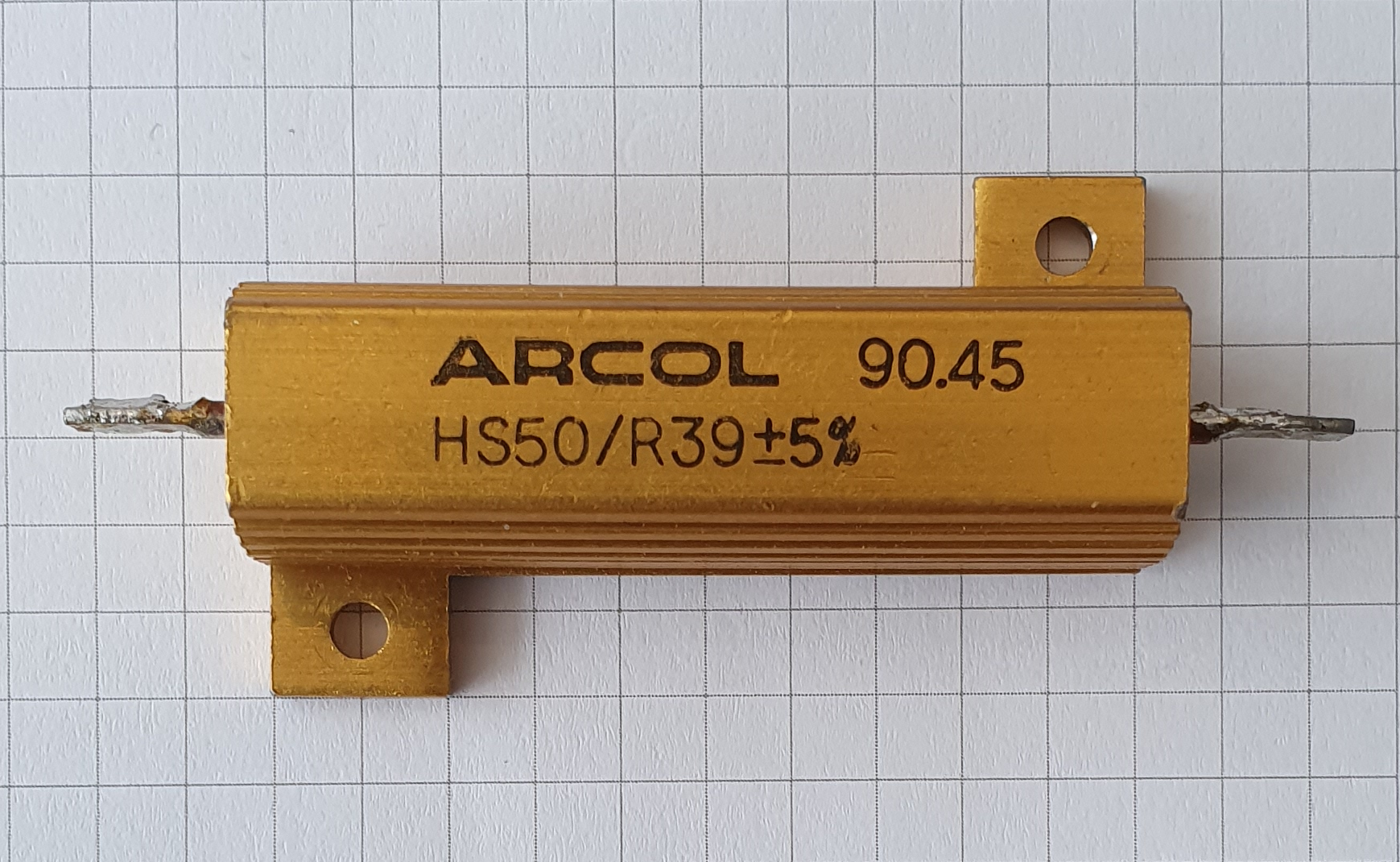
8.2.3 Why wirewound owns high power, and the ratings ladder
The ratings ladder makes the point plainly. Ordinary film resistors top out at a few watts because their thin element cannot be made to shed more heat without an impractically large body. Wirewound spans from about one watt — a small axial part — up through the ten-to-a-hundred-watt aluminium-clad and vitreous ranges, into the kilowatt class for edge-wound grid resistors and braking banks, and beyond, into the many-kilowatt load banks used to test generators and dissipate regenerated energy in traction and elevator drives. What changes across that ladder is not the physics of the element but the thermal package: a bigger body, a hotter-tolerant coating, a metal case, a heatsink, forced air, or a bank of elements in open air. The power rating of any of these is a thermal specification tied to a stated mounting and airflow, and it derates as ambient temperature rises exactly as the next volume, on power and derating, develops in full. The element itself is nearly indestructible by film standards; the whole art of the high-power resistor is moving its heat out before its own temperature climbs past what the coating and the terminations can stand.
8.2.4 The inductance liability: a resistor that is literally a coil
Wirewound’s one intrinsic electrical drawback is written directly into its geometry. A coil of wire is an inductor. A resistor wound as a simple helix — every turn in the same direction — is, magnetically, a small solenoid, and it therefore has a series inductance in addition to its resistance. At DC and low frequencies that inductance is invisible; the part reads its rated ohms. But its impedance climbs with frequency as Z ≈ √(R² + (2πfL)²), so a wirewound that measures a clean value on a bench ohmmeter can look quite different to a fast pulse edge or an RF signal, adding phase shift, ringing, and an apparent rise in impedance that has nothing to do with its resistance. This is the same parasitic inductance treated in the equivalent-circuit and frequency-response material of Volume 3, and it is the reason the coils dive in this same passive-components program spends so long on solenoid inductance: a power wirewound is, unavoidably, a resistor and an inductor at once. For a DC load or a mains-frequency dropper the inductance is harmless. For a current-sense element watching a switching edge, a snubber, an RF dummy load, or the feedback path of a fast amplifier, it can be disqualifying — and that is what the non-inductive winding techniques exist to fix.
8.2.5 Non-inductive winding: Ayrton–Perry, bifilar, and reverse-pitch
The cure is to wind the wire so that its magnetic field cancels itself. The most important and most effective scheme is the Ayrton–Perry winding, named for the nineteenth-century physicists William Ayrton and John Perry. Instead of one helix, the element is wound as two windings running in opposite directions on the same former, connected so that the current flows out along one and back along the other. Because the two windings carry the same current in opposite senses, the magnetic field each produces points the opposite way, and the two fields very nearly cancel — leaving a part with almost no net inductance while its resistance is unchanged. Geometrically, the current runs down the core and back again, so the effective loop area the field encloses shrinks close to zero, and the inductance shrinks with it. Ayrton–Perry winding also happens to reduce the part’s self-capacitance and gives it the most nearly ideal, frequency-flat impedance of any wirewound construction, which is why precision and high-frequency wirewounds are built this way.
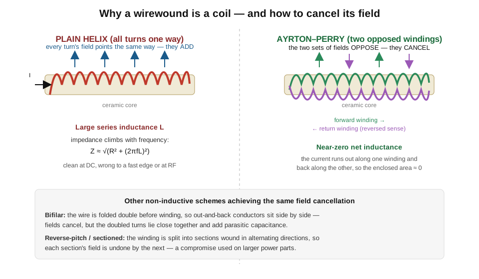
Two related techniques reach the same goal by different geometry (Figure 2). A bifilar winding folds the wire double before winding, so that the outgoing and returning conductors lie side by side through every turn; their fields oppose and cancel just as in Ayrton–Perry, but because the doubled turns sit so close together the scheme adds appreciable parasitic capacitance, which can itself limit high-frequency accuracy. A reverse-pitch or sectioned winding splits the element into several sections wound in alternating directions, so that each section’s field is undone by the next; it is a coarser compromise, cheaper to make and used on larger power parts where a modest inductance reduction is enough. All three trade some manufacturing cost and often some usable resistance range for a dramatic drop in inductance, and the specialty-resistor volume returns to non-inductive construction where it treats current-sense and RF resistors. The point to carry forward is that a wirewound’s inductance is a consequence of how it is wound, not a law of nature, and can be engineered away when the application demands it.
8.3 Precision wirewound: the metrology heritage
Wound from a different wire on a different mission, the precision wirewound resistor occupies the opposite corner from its power cousin: not the highest wattage but the highest accuracy and stability that a wound element can reach. Here the wire is not heavy nichrome but a fine gauge of a special low-temperature-coefficient alloy — classically manganin (a copper-manganese-nickel alloy) or Evanohm and Karma (nickel-chromium alloys with small additions), materials formulated specifically so that their resistance barely changes with temperature. Manganin’s resistance-temperature curve is nearly flat around room temperature and its thermal EMF against copper is very small, which is exactly what a standard resistor needs; Evanohm and Karma push the temperature coefficient even lower and hold it over a wider range. Wound in many turns of this fine wire, aged and annealed to relieve mechanical stress, and often sealed in oil or an inert atmosphere, a precision wirewound can hold a temperature coefficient of only a few ppm/°C — figures of ±1 to ±5 ppm/°C are ordinary for good parts — and a tolerance down to ±0.1%, ±0.01%, or, for the finest laboratory grades, ±0.005%. Its long-term stability is excellent, and its noise is essentially the thermal-noise floor, because a continuous metal wire has none of the granular micro-contacts that make carbon and thick film noisy.
This combination — sub-ppm-class tempco, ppm-class tolerance, superb stability, negligible excess noise — is why precision wirewound was for a century the material of the laboratory. The standard resistor, the reference against which other resistances are calibrated, was traditionally a precision manganin winding in a sealed, temperature-controlled can. The resistance decade box — the instrument that lets an experimenter dial an arbitrary resistance from a bank of switched precision elements — was built from precision wirewound resistors, decade by decade, and the four-terminal precision shunts used to measure large currents were wound the same way. That metrology heritage is taken up in detail in the measuring-and-testing volume, which covers standard resistors, bridges, and the four-wire technique; the note here is that when the value itself must be trusted, wire held the crown long before foil and thin film arrived to challenge it.
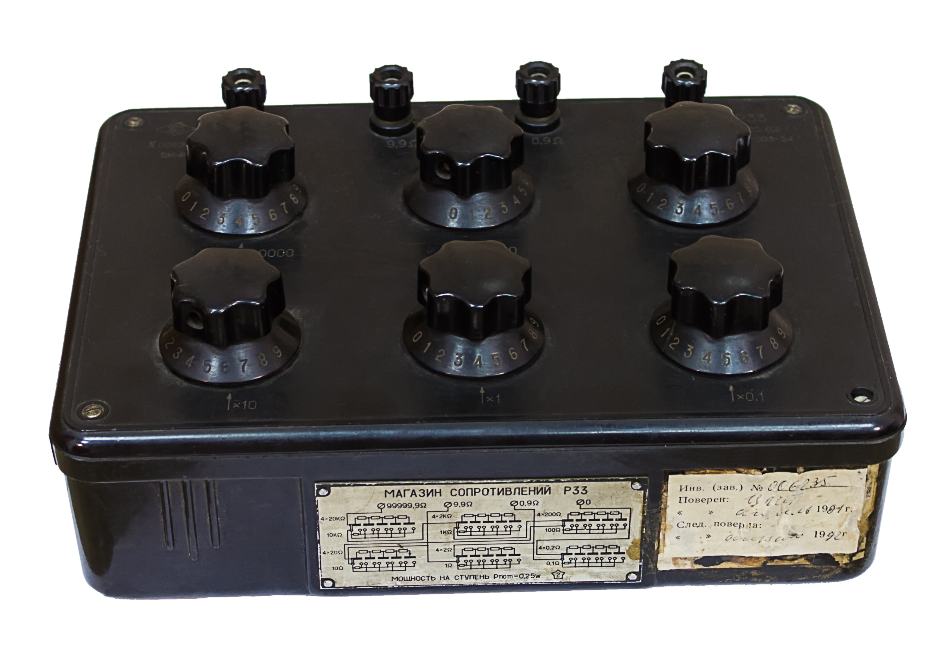
Precision wirewound has one unavoidable limitation, and it is the same one that dogs its power cousin: it is still a coil of wire. Even wound Ayrton–Perry, a many-turn precision winding has some residual inductance and capacitance, so its usefulness falls off at high frequency. A precision wirewound is superb at DC and low frequencies — where standard resistors and decade boxes live — but it is not the part to reach for at radio frequencies or for fast pulse work, where its reactance intrudes. For those cases, and for the very highest DC stability, the two film-descended precision technologies that follow do better: bulk metal foil, and, at somewhat looser grades, thin film.
8.4 Bulk metal foil: the stability champion
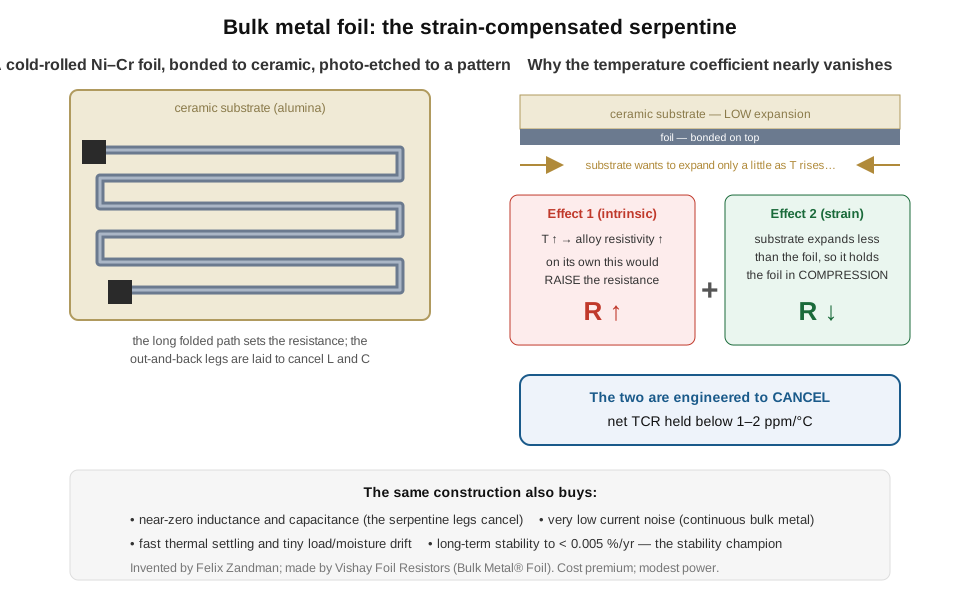
At the very top of the stability ladder sits a construction that belongs to no other family and that is generally regarded as the finest fixed resistor made: the bulk metal foil resistor, developed by Felix Zandman and made most famously by Vishay Foil Resistors (formerly part of the Vishay Precision Group) under the Bulk Metal and Z-Foil trademarks. Its element is neither wound nor sputtered nor fired. It is a cold-rolled foil of a nickel-chromium alloy — a true piece of bulk metal, thicker than any sputtered thin film — that is bonded to a ceramic substrate and then photo-etched into a fine serpentine pattern whose folded length sets the resistance (Figure 4). It reads, at first glance, like a thin-film chip built from a rolled foil instead of a vapor-deposited layer, and the extra thickness of genuine, stress-relieved bulk metal is central to why it performs the way it does.
8.4.1 The strain-compensation mechanism
What makes bulk foil the stability champion is a clever piece of combined mechanical and electrical design, and it is worth stating in detail because it is genuinely different from every other resistor. Every resistor’s value changes with temperature for two combined reasons: the alloy’s own resistivity changes, and the part physically expands, changing the element’s geometry. In an ordinary resistor those two effects simply add into the net temperature coefficient. In a bulk-foil resistor they are set against each other. The foil is bonded to a ceramic substrate whose thermal expansion is deliberately lower than the foil’s own. As temperature rises, the foil’s intrinsic resistivity climbs, which on its own would raise the resistance. But the low-expansion substrate refuses to grow as much as the foil wants to, so it holds the bonded foil in compression — and a resistive foil under compressive strain has its resistance lowered through the strain-gauge effect (the same piezoresistive mechanism that makes a foil strain gauge work, exploited here in reverse). The magnitudes are engineered so that the resistance-lowering strain effect very nearly cancels the resistance-raising resistivity effect, leaving a net temperature coefficient below 1 to 2 ppm/°C — better than the best precision wirewound and far beyond any film. This is not a happy accident of materials but a designed cancellation, tuned by the choice of substrate and the alloy’s gauge factor.
8.4.2 What else the construction buys, and where it is worth the cost
The same photo-etched foil-on-ceramic construction buys several other advantages at once. Because the serpentine’s out-and-back legs are laid out to oppose one another, the element has essentially no significant inductance or capacitance — orders of magnitude below a wirewound — so a foil resistor stays flat and resistive from DC well up in frequency, unlike precision wirewound. Because the element is a continuous piece of bulk metal, its current (excess) noise is very low, at the thermal floor. Because the foil has real thickness and thermal mass and is bonded flat to ceramic, it settles thermally very fast — its resistance stabilizes within microseconds of a power change rather than drifting for seconds — and it shows tiny load-life and moisture drift. And its long-term stability is the best available, with year-to-year drift held below about 0.005% (50 ppm) on good parts, and the tightest tolerances of any resistor, down to ±0.01% and ±0.001% on selected grades.
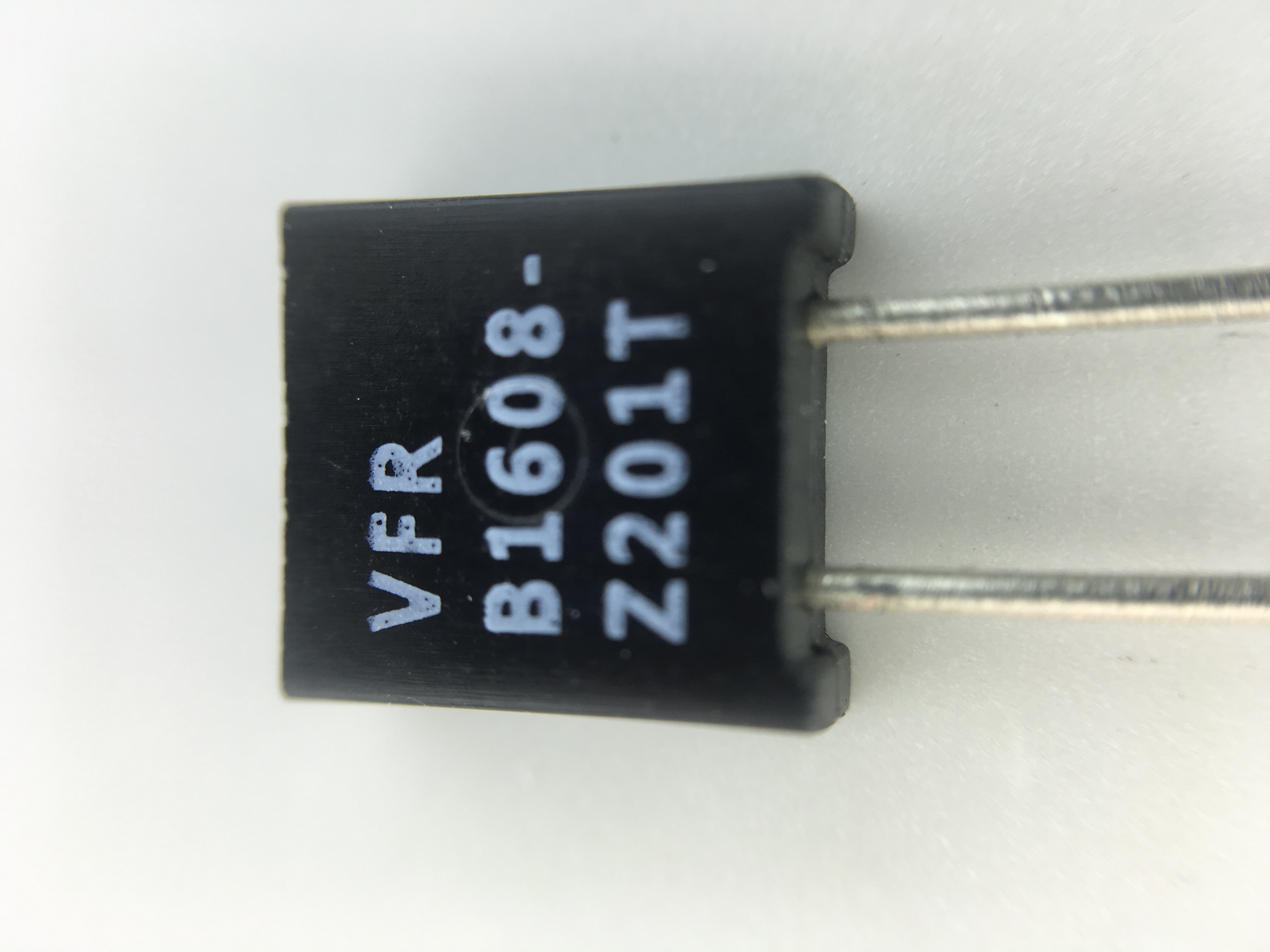
The cost of all this is a genuine price premium — a bulk-foil resistor can cost many times a precision thin-film part and orders of magnitude more than a thick-film chip — and a modest power rating, since the small foil element is not built to dissipate much. So bulk foil is reserved for the places that truly justify it and can afford it: voltage and current references, precision instrumentation front ends, metrology and calibration standards, strain-gauge bridges, medical and aerospace hardware, and any circuit whose accuracy budget is set by the resistor rather than by anything else. Where the last part per million of stability earns its keep, nothing else competes; everywhere else, it is overkill.
8.5 The chip pair: thick film versus thin film
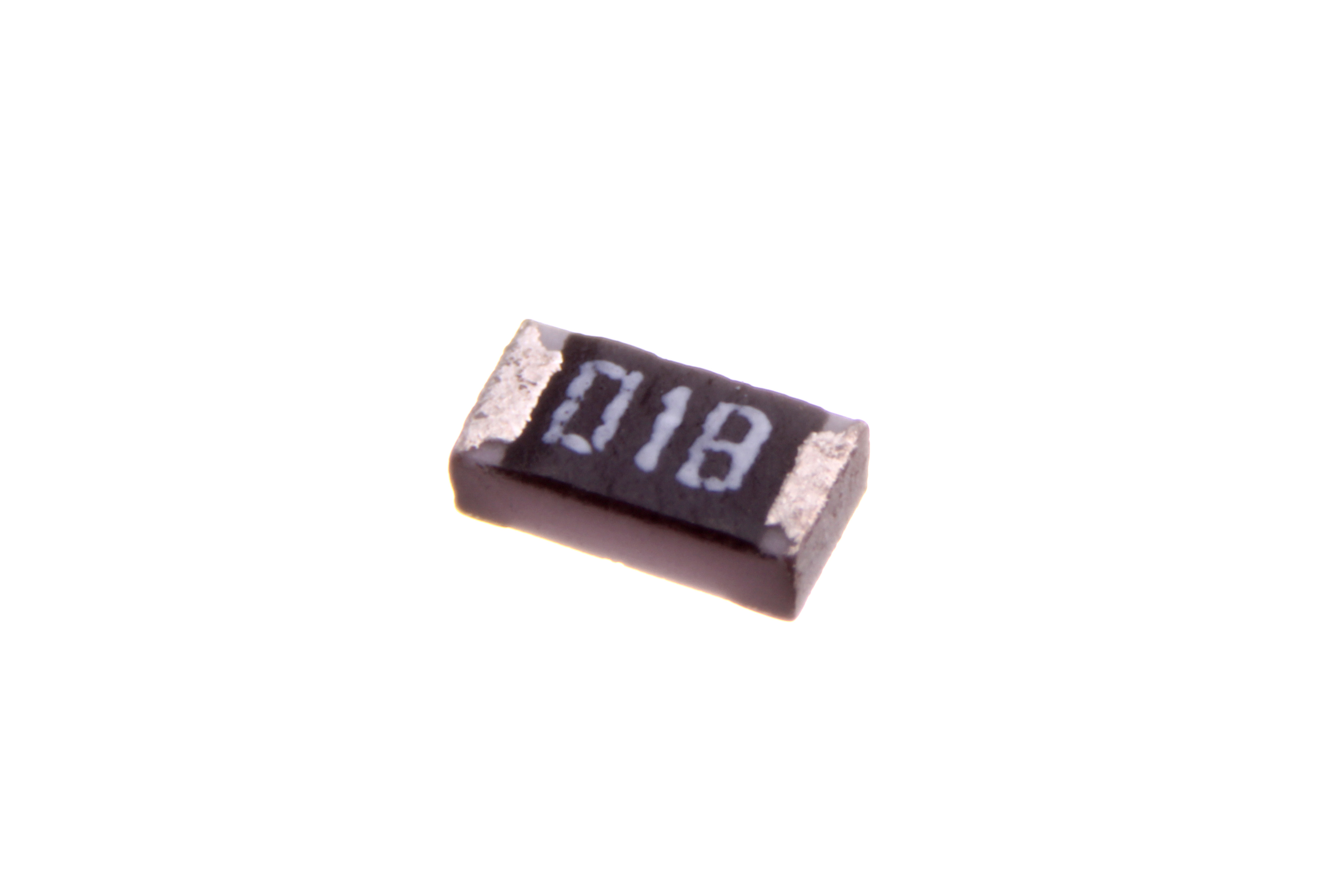
Between the power and precision extremes, and vastly outnumbering both, sit the two surface-mount chip technologies that Volume 5 followed through the factory and that this volume now compares as finished parts a designer must choose between. Both are films on an alumina substrate, both come in the same tiny standardized chip bodies (0402, 0603, 0805, 1206 and the rest), and both look identical across the bench. Their difference is entirely in how the resistive film is put down, and that difference cascades into a wide gap in every specification that matters (Figure 5).
Thick film is made by screen-printing a ruthenium-dioxide (RuO₂) paste onto the alumina and firing it at around 850 °C, leaving a grainy glass-and-oxide composite — a cermet — roughly ten to fifty microns thick. Conduction happens through a percolating network of touching RuO₂ grains in glass, and that microstructure sets its character: a moderate temperature coefficient of about ±100 to ±200 ppm/°C (±50 on better grades), a nontrivial and slightly field-dependent voltage coefficient, higher excess noise than a continuous film, and only coarse ratio matching between neighboring elements. Its tolerance runs ±1% to ±5%, with ±0.5% available. What thick film has instead is unbeatable cost and manufacturability: it is the cheapest resistor made, screen-printable a thousand at a time, and it accounts for well over ninety-nine percent of all chip resistors produced. It also tends to carry a slightly higher working voltage and power in a given body size than thin film. For the overwhelming majority of digital and consumer circuits — pull-ups, pull-downs, biases, current limits, ordinary dividers — a thick-film chip at 1% and 100 ppm/°C is entirely adequate, and its price is decisive.
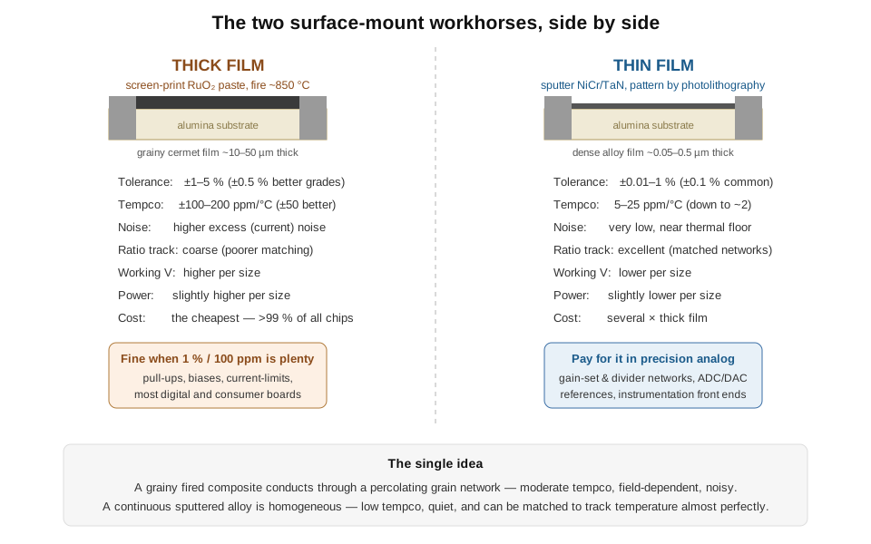
Thin film is made by sputtering a dense, ultra-thin alloy — usually nichrome (NiCr) or tantalum nitride (TaN) — onto the alumina, only tens to a few hundred nanometres thick, and then patterning it by photolithography, the vocabulary of semiconductor fabrication rather than screen printing. The result is a continuous, homogeneous alloy film with an exactly defined geometry, and everything that makes thin film the precision choice follows from that. Its temperature coefficient is low and repeatable, routinely 5 to 25 ppm/°C and as low as about 2 ppm on selected parts — an order of magnitude better than thick film — and, crucially, neighboring elements can be built with matched, opposing coefficients so that a whole network tracks temperature almost perfectly, which is why precision divider and gain-setting networks are thin film. Its excess noise is very low, near the thermal floor, which matters for low-level analog signal paths. And because photolithography defines the geometry precisely and the film is then laser-trimmed, tolerances of ±0.1%, ±0.05%, and tighter are ordinary. The price is literal: thin-film chips cost several times their thick-film equivalents, carry somewhat less power and a lower maximum working voltage in a given size, and tolerate less energy in a surge. So the two split the market cleanly. Thick film handles the trillions of ordinary parts where cost rules; thin film is paid for where precision rules — the instrumentation amplifier’s gain network, the data converter’s reference divider, the sensor bridge, and anywhere ratio accuracy and low drift earn their keep.
A designer choosing between them can apply a simple rule. If the circuit is digital or undemanding analog and a one-percent, hundred-ppm part will do, use thick film and save the money — it is also the tougher part against pulses and higher voltage. If the circuit’s accuracy depends on the resistor — a precise divider ratio, a stable gain, a low-drift reference, a matched pair whose two halves must track — pay for thin film, or, at the very top, for bulk foil. The chip package is the same; only the film underneath, and the price, differ.
8.6 The master matrix: every fixed type at a glance
Everything in the two fixed-types volumes can now be consolidated into a single comparison, the reference centerpiece of the fixed-resistor survey. The matrix below rates all nine fixed constructions — the four composition-and-film families of Volume 7 plus the five power-and-precision types of this volume — against the specifications a designer actually weighs: tolerance, temperature coefficient, maximum power, excess noise, high-frequency behavior and inductance, long-term stability, relative cost, and the application each is really for. Read down a column to rank the types on one axis; read across a row to get a type’s whole personality. The figures are representative catalog ranges, not guarantees — the specific datasheet always governs — but the pattern they show is stable and worth internalizing, because it is the map a designer uses to pick a resistor technology before ever opening a datasheet.
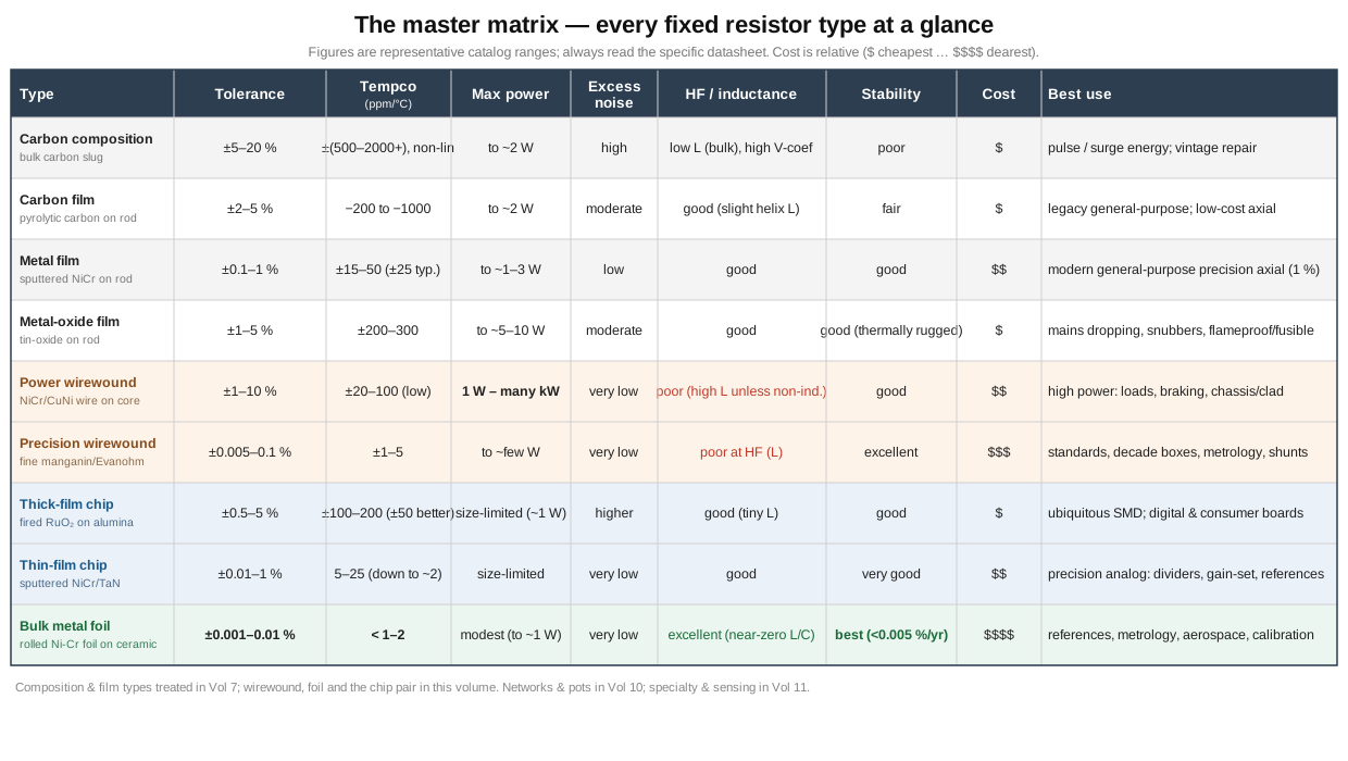
Table 1 — The master matrix: every fixed type at a glance
| Type | Tolerance | Tempco (ppm/°C) | Max power | Excess noise | HF / inductance | Stability | Cost | Best use |
|---|---|---|---|---|---|---|---|---|
| Carbon composition | ±5–20% | ±(500–2000+), non-linear | to ~2 W | high | low L (bulk), high V-coefficient | poor | $ | pulse / surge energy; vintage repair |
| Carbon film | ±2–5% | −200 to −1000 | to ~2 W | moderate | good (slight helix L) | fair | $ | legacy general-purpose axial |
| Metal film | ±0.1–1% | ±15–50 (±25 typ.) | to ~1–3 W | low | good | good | $$ | modern general-purpose precision axial (1%) |
| Metal-oxide film | ±1–5% | ±200–300 | to ~5–10 W | moderate | good | good (thermally rugged) | $ | mains dropping, snubbers, flameproof/fusible |
| Power wirewound | ±1–10% | ±20–100 (low) | 1 W – many kW | very low | poor (high L unless non-inductive) | good | $$ | high power: loads, braking, chassis/clad |
| Precision wirewound | ±0.005–0.1% | ±1–5 | to ~few W | very low | poor at HF (residual L) | excellent | $$$ | standards, decade boxes, metrology, shunts |
| Thick-film chip | ±0.5–5% | ±100–200 (±50 better) | size-limited (~1 W) | higher | good (tiny L) | good | $ | ubiquitous SMD; digital & consumer boards |
| Thin-film chip | ±0.01–1% | 5–25 (down to ~2) | size-limited | very low | good | very good | $$ | precision analog: dividers, gain-set, references |
| Bulk metal foil | ±0.001–0.01% | < 1–2 | modest (to ~1 W) | very low | excellent (near-zero L/C) | best (<0.005%/yr) | $$$$ | references, metrology, aerospace, calibration |
Several patterns in the matrix repay a second look. Tolerance and tempco track together and both improve down the precision axis, from carbon composition’s ragged ±20% and thousand-ppm swing to bulk foil’s ±0.001% and sub-ppm coefficient — because both are consequences of the same thing, a uniform, stable, well-trimmed element. Noise splits by microstructure, not by price bracket: the granular materials (carbon composition, carbon film, thick film) are the noisy ones, while every continuous-metal element (metal film, all wirewound, thin film, foil) is quiet, which is why a low-level analog front end avoids carbon and thick film regardless of tolerance. High-frequency behavior is the wirewound family’s weakness and the chip and foil family’s strength: the wound types carry inductance that only non-inductive winding partly tames, whereas foil and small chips are nearly ideal to high frequency. Power is almost entirely a wirewound and metal-oxide story, because dissipation is a thermal problem that a rugged bulk element and a heat-shedding package solve and a precision film cannot. And cost rises steeply toward the precision corner, so the practical skill is choosing the cheapest technology that still meets the one specification the circuit actually cares about — not paying for foil-grade stability in a pull-up, and not economizing with a thick-film chip in a reference divider.
8.7 Bridging forward
This volume and the last together account for every fixed resistor — the parts whose resistance is set at manufacture and does not change. Volume 7 covered the composition and film mainstream; this one covered the power and precision extremes and placed the whole family on a single map. What remains of the resistor world lies in three directions the coming volumes take up. The power rating that recurred throughout this volume — why an aluminium-clad part carries fifty watts and an open one five, how any rating derates with temperature and mounting — is the entire subject of the next volume, on power and derating. The parts whose resistance is meant to vary or to come in matched groups — potentiometers, rheostats, trimmers, and the resistor networks and arrays that put many elements in one package, exploiting exactly the thin-film ratio-tracking this volume praised — are the subject of the networks-and-potentiometer volume. And the specialty and sensing cousins — the four-terminal current-sense shunts, high-voltage and fusible resistors, the non-inductive constructions in their own right, and the resistors that are meant to change with temperature, voltage, light, or strain — are the subject of the specialty volume. Between them, the fixed types collected in these two volumes are the foundation on which all of those build.
Comments (0)