Resistors · Volume 6
Reading Resistors: The Color Code, the E-Series, and SMD Codes
6.1 Why a resistor wears its value on its sleeve
A resistor is a cylinder a few millimetres long, or a chip the size of a grain of coarse salt. There is no room on it to print “47 000 ohms, plus or minus five percent, one hundred parts per million per degree Celsius.” Even if there were, the ink would have to survive tumbling in a bin with ten thousand identical parts, a wash of flux and solvent, the heat of a soldering iron, and years of dust — and it would have to be readable no matter which way the part happened to land on the bench. The industry’s answer, worked out in the 1920s and refined ever since, is a code: a compact, orientation-tolerant, cheap-to-apply mark that carries the value, the tolerance, and sometimes the temperature behaviour in a form a human or a machine can decode at a glance.
Two great families of code are in use, and this volume is a field guide to both. The older is the color code — the painted bands that ring a through-hole, axial-leaded resistor. The newer, forced on the industry by the surface-mount chip that is far too small to band, is the printed numeric code — a two-, three-, or four-character mark stamped on the flat top of the chip. Underneath both sits a third piece of the puzzle that confuses more newcomers than either code does: the E-series, the reason resistors come in the strange-looking values 10, 12, 15, 18, 22, 27, 33 and not in the round numbers a beginner expects. Learn the color bands, learn why the values are what they are, and learn the chip markings, and there is no fixed resistor made that cannot be read. The full lookup tables live in the reference volume; this volume teaches the reading.
6.2 The color code: ten colors doing three jobs
The color code is defined by the international standard IEC 60062 (the same document that governs capacitor and inductor marking). Its foundation is a mapping of ten colors to the ten digits, and the elegance of the scheme is that those same ten colors are then reused, unchanged, to mean powers of ten in the multiplier position, and reused again — with a few additions — to mean tolerances. One palette, three jobs.
6.2.1 A note on mnemonics
Generations of technicians memorised the digit order with a mnemonic sentence whose first letters spell the colors: black, brown, red, orange, yellow, green, blue, violet, grey, white. Many of the traditional sentences that circulated in mid-twentieth-century shop culture were crude and openly racist, and they should be retired without ceremony; they teach nothing that a neutral phrase cannot. A clean substitute that has been used for decades is “Bad beer rots our young guts but vodka goes well” — the initials run black-brown-red-orange-yellow-green-blue-violet-grey-white in order. Any sentence will do; the only thing that must be exact is the sequence, because the whole code hangs on it.
6.2.2 The digit and multiplier colors
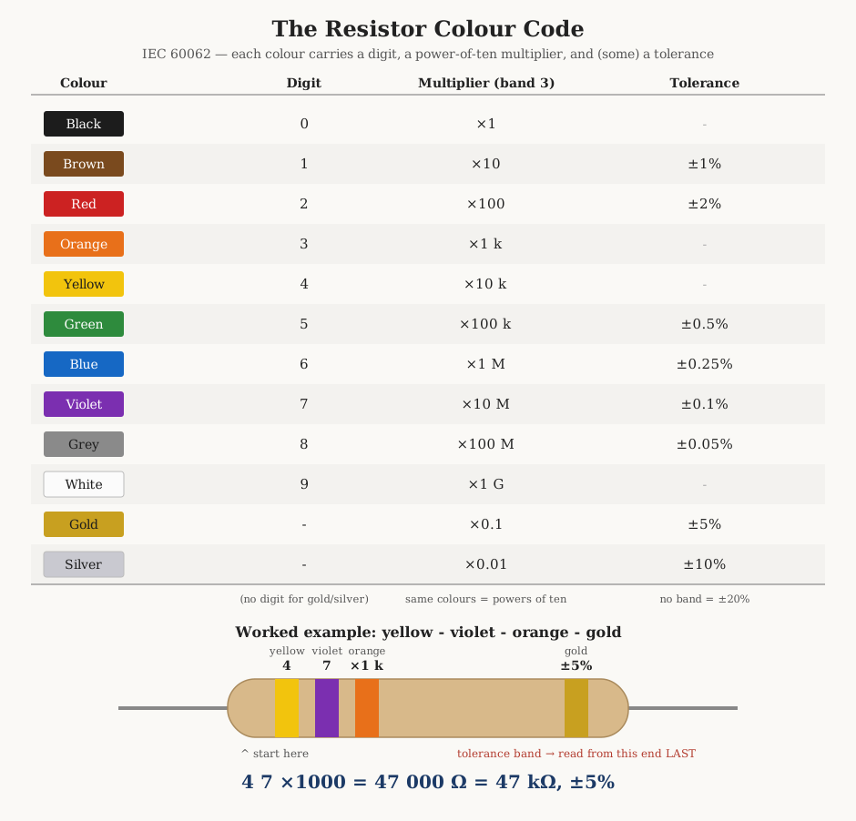
The ten digit colors run in the order of the visible spectrum, bracketed by black at the dark end (zero) and white at the bright end (nine), with grey just before white for eight. The same colors, read in the multiplier band, mean the power of ten by which the significant figures are scaled — black is 10⁰ = ×1, brown is ×10, and so on up to white at ×10⁹. Two extra colors, gold and silver, appear only as multipliers (and as tolerances); they extend the scale downward to ×0.1 and ×0.01, which is how sub-ten-ohm values are marked. Figure 1 gathers the whole system — the digit column, the multiplier column, and the tolerance column — into a single chart, with a worked example resistor beneath it.
The digit-and-multiplier core of the code is worth committing to a table, because it is the part that never changes:
Table 1 — is the part that never changes
| Color | Digit | Multiplier (band) | Tolerance |
|---|---|---|---|
| Black | 0 | ×1 | — |
| Brown | 1 | ×10 | ±1% |
| Red | 2 | ×100 | ±2% |
| Orange | 3 | ×1 k | — |
| Yellow | 4 | ×10 k | — |
| Green | 5 | ×100 k | ±0.5% |
| Blue | 6 | ×1 M | ±0.25% |
| Violet | 7 | ×10 M | ±0.1% |
| Grey | 8 | ×100 M | ±0.05% |
| White | 9 | ×1 G | — |
| Gold | — | ×0.1 | ±5% |
| Silver | — | ×0.01 | ±10% |
| (none) | — | — | ±20% |
6.2.3 The tolerance band
The tolerance band states how far the real part may stray from the marked value, as a percentage. On the cheap end, gold means ±5% and silver means ±10%, and these two are by far the most common tolerance bands a hobbyist meets; a resistor with no tolerance band at all is the old ±20% grade. On the precision end, the digit colors do double duty: brown is ±1%, red ±2%, and the tight grades run green ±0.5%, blue ±0.25%, violet ±0.1%, grey ±0.05%. The reason gold and silver were chosen for the loose tolerances is deliberate — they are metallic, lustrous, and impossible to confuse with the matte digit colors, so the eye finds the tolerance band first and orients the part from it.
6.2.4 Four bands, five bands, six bands
How many bands a resistor carries depends on how precisely it must be specified.
A four-band resistor uses two significant figures, a multiplier, and a
tolerance: digit — digit — multiplier — tolerance. Two significant figures is
enough for the ±5% and ±10% grades, whose values come from the coarser E-series
(more on that below), so four bands is the standard dress of the everyday carbon-
and metal-film resistor.
A five-band resistor uses three significant figures, a multiplier, and a
tolerance: digit — digit — digit — multiplier — tolerance. The extra digit is
what a ±1% or tighter part needs, because its values are drawn from the dense
E96 series, which is specified to three figures. Five bands is the standard dress of
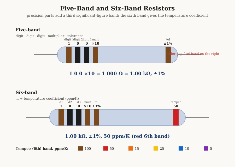
the modern precision metal-film resistor. Figure 2 reads one.
A six-band resistor adds a final band for the temperature coefficient —
the ppm/°C figure covered below — giving three digits — multiplier — tolerance — tempco. Six bands appear only on genuinely high-stability parts where drift with
temperature is part of the specification.
6.2.5 The temperature-coefficient band
The sixth band gives the temperature coefficient of resistance (TCR), the rate at which the value drifts with temperature, in parts per million per degree Celsius (ppm/°C, numerically the same as ppm/K). Lower is better — a 5 ppm/°C part changes five parts per million of its value for each degree, a 100 ppm/°C part twenty times as much. The common assignment is:
Table 2 — as much. The common assignment is
| 6th band | Tempco |
|---|---|
| Brown | 100 ppm/°C |
| Red | 50 ppm/°C |
| Orange | 15 ppm/°C |
| Yellow | 25 ppm/°C |
| Blue | 10 ppm/°C |
| Violet | 5 ppm/°C |
Note the two oddities that trip people up: orange (15) is lower than yellow (25), so the tempco band does not simply track the digit order, and different manufacturers occasionally use slightly different sets (some data sheets add green at 20 ppm/°C or grey at 1 ppm/°C). When the exact tempco matters, the part number and data sheet are authoritative; the band is a convenience.
6.2.6 Orientation: which end is the beginning
A code is useless if it can be read backwards, and a resistor has no arrow. Three rules settle the direction every time.
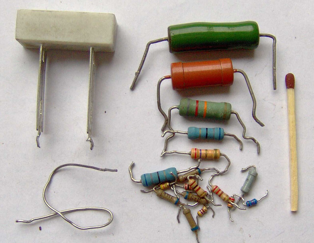
First, the tolerance band goes on the right — so read toward it, not from it. On a four- or five-band part the gold or silver tolerance band is unmistakable, and it is almost always at one end; put that end on your right and read leftward-to- rightward from the far end. Second, there is a wider gap between the last two bands (the multiplier and the tolerance, or the tolerance and the tempco) than between the significant-figure bands, which are grouped tight together at the starting end; that gap is the visual comma that tells you which cluster is the “number.” Third — the fallback when a part is banded at both ends or the colors are ambiguous — gold and silver are never a first band. A resistor’s leading digit cannot be gold or silver (they carry no digit), so if you find gold or silver at one end, that end is the tolerance and belongs on the right. Between the three rules, an axial resistor can always be oriented; Figure 3 shows the real article.
6.2.7 Worked examples
A few decodings, run end to end, cement the method. Read each from the significant- figure end toward the tolerance band on the right.
- Brown — black — red — gold. Digits 1 and 0 give 10; the red multiplier is ×100; gold is ±5%. So 10 × 100 = 1 kΩ, ±5% — the workhorse pull-up value.
- Yellow — violet — orange — gold. Digits 4 and 7 give 47; orange is ×1000; gold is ±5%. So 47 × 1000 = 47 kΩ, ±5% (the example drawn in Figure 1).
- Red — red — black — gold. Digits 2 and 2 give 22; black is ×1; gold is ±5%. So 22 × 1 = 22 Ω, ±5% — note that a black multiplier means “multiply by one,” a point that catches beginners who expect a multiplier always to add zeros.
- Brown — black — black — brown — brown (five-band). Digits 1, 0, 0 give 100; the brown multiplier is ×10; brown is ±1%. So 100 × 10 = 1.00 kΩ, ±1% — the most common precision resistor in existence. (For a five-band 100 Ω ±1% the multiplier would instead be black: brown-black-black-black-brown, i.e. 100 × 1.)
6.2.8 Common misreads
The color code’s weakness is the eye. Under warm incandescent light or on an aged, dusty body, red, brown, and orange collapse toward one another, and a misjudged orange-for-red turns a 47 kΩ into a 4.7 kΩ — a factor of ten. The cure is boring but reliable: read the part under cool, bright, even light, and when a value is load-bearing, measure it with a meter rather than trusting the paint. Faded parts sometimes leave the multiplier and tolerance bands more robust than the digit bands (different pigments age differently), so cross-check the decoded value against the E-series — if the code decodes to a value that is not a standard E-series number, the reading is almost certainly wrong. Finally, one band has nothing to do with value at all: on some military and high-reliability axial parts an extra band (often the widest, at the far end) encodes a failure-rate or “reliability” level, not a tolerance or tempco; on those parts the count of bands and the placement of the reliability band must be read against the specific military drawing, not the civilian code.
6.3 The E-series: why 10, 12, 15, 18, 22, 27…
Sooner or later every newcomer asks the obvious question: why can you buy a 47 kΩ resistor and a 470 kΩ resistor but not a 40 kΩ or a 500 kΩ? Why do the values march in the peculiar sequence 10, 12, 15, 18, 22, 27, 33, 39, 47, 56, 68, 82 and then repeat, ten times bigger? The answer is one of the quietly beautiful pieces of engineering standardisation, and it is inseparable from tolerance.
6.3.1 The logarithmic answer, tied to tolerance
Imagine you must stock a range of resistors that can cover any required value to within, say, ±20%. You do not need a value at every integer — you need values spaced closely enough that some stocked value is always within ±20% of whatever a designer asks for. Because a ±20% window is a ratio (a part is within 20% if it lies between 0.8× and 1.2× the target), the stocked values should be spaced by a constant ratio, not a constant difference — which means they should be equally spaced on a logarithmic scale. Cover one decade (a factor of ten) in N such steps and each value is approximately
value ≈ 10^(k/N), for k = 0, 1, 2, … N−1
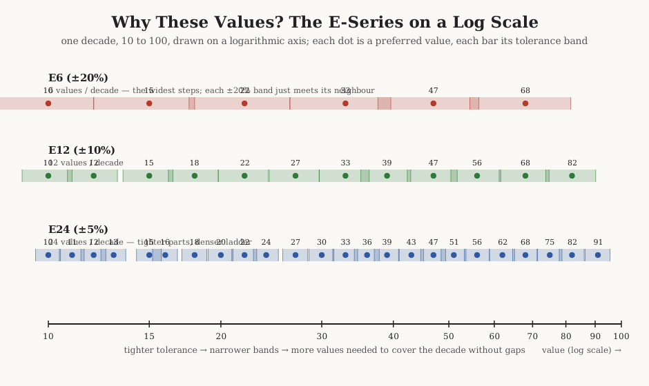
rounded to a sensible number of significant figures. Choose N so that each value’s tolerance band just reaches its neighbour’s, and the whole decade is tiled with no gaps and little overlap. That is precisely what the E-series (defined in IEC 60063) does. The name comes from the exponential spacing, and the number after the E is N, the count of values per decade. Figure 4 plots three of the series on a logarithmic axis with their tolerance bands drawn, so the tiling is visible rather than asserted.
6.3.2 From E6 to E192
Each halving of tolerance calls for a doubling of the value count, so the series form a ladder, each tier pairing naturally with a tolerance grade:
Table 3 — form a ladder, each tier pairing naturally with a tolerance grade
| Series | Values/decade | ~10^(k/N) step | Sig. figs | Usual tolerance |
|---|---|---|---|---|
| E6 | 6 | ×1.47 | 2 | ±20% |
| E12 | 12 | ×1.21 | 2 | ±10% |
| E24 | 24 | ×1.10 | 2 | ±5% |
| E48 | 48 | ×1.05 | 3 | ±2% |
| E96 | 96 | ×1.02 | 3 | ±1% |
| E192 | 192 | ×1.01 | 3 | ±0.5% and tighter |
E6, E12, and E24 use two significant figures; E48, E96, and E192 use three, which is exactly why the tighter tolerances need a five-band color code or a four-digit chip mark — two figures cannot express 4.87 kΩ. E192 (and E96) are also the series used for 0.5%, 0.25%, and 0.1% parts; the same value ladder simply pairs with a tighter tolerance guarantee.
6.3.3 The full E24 ladder
E24 is the series most worth knowing by heart, because it contains E12 and E6 inside it and because ±5% parts are ubiquitous. Its 24 values are:
Table 4 — it and because ±5% parts are ubiquitous. Its 24 values are
| 10 | 11 | 12 | 13 | 15 | 16 | 18 | 20 |
| 22 | 24 | 27 | 30 | 33 | 36 | 39 | 43 |
| 47 | 51 | 56 | 62 | 68 | 75 | 82 | 91 |
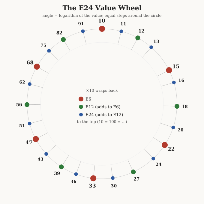
The E12 subset (±10%) drops every other value: 10, 12, 15, 18, 22, 27, 33, 39, 47, 56, 68, 82. The E6 subset (±20%) thins it again: 10, 15, 22, 33, 47, 68 — the six values whose ±20% bands, in Figure 4, exactly tile the decade. Figure 5 arranges the whole E24 set as a wheel, placing each value at an angle equal to its logarithm, which makes the equal spacing literal and shows how E6 and E12 nest inside E24.
6.3.4 The rounding quirks
If the values were the exact geometric steps 10^(k/24), the E24 list would read 10.0, 11.0, 12.0, 13.1, 14.3, 15.6, 17.0, 18.6, 20.3, 22.2, and so on. The committee rounded these to two figures — but not always to the nearest one, and the irregularities are historical rather than mathematical. The exact fourth step is about 13.3, rounded to 13; the fifth is 14.7, but there is no 14 in E24 — it jumps to 15. The step near 26 was rounded to 27 rather than 25, and the one near 31 to 30 then 33, giving the famous run …22, 24, 27, 30, 33… that looks lumpy but is smooth on a log scale. The trio 2.7, 3.3, 3.9 (i.e. 27, 33, 39) is the one that beginners find least “round,” yet it is exactly the even-log spacing doing its job.
Two subtler cautions matter to the precision designer. First, the rounding means the E-series are not strict supersets of one another for every value: most E48 values reappear in E96, and most E24 values look like they should sit in E96 — but because E24 was rounded from a 24-step grid and E96 from a 96-step grid, a few values differ in the last figure. E24’s 33 corresponds to E96’s 332 at three figures, not 330; E24’s 27 aligns with E96’s 274, not 270. Do not assume a two-figure E24 value is simply the three-figure E96 value with a trailing zero. Second, the tighter series were standardised later and occasionally “corrected” roundings, so old and new tables can disagree in the last digit for a handful of values — always take three-figure values from a current IEC 60063 table.
6.3.5 Using the E-series in practice
The practical upshot is liberating: you almost never need an exact value. Since every real resistor already carries a ±1% to ±20% tolerance, asking for “1 kΩ exactly” is meaningless — the part you buy is guaranteed only to lie in a band. So a designer picks the nearest E-series value to the calculated ideal and checks that the resulting circuit still meets its requirement across the tolerance band. Bias networks, pull-ups, LED current limiters, and the like are entirely happy with the nearest E24 value.
When a design genuinely needs a value between the standard steps — a precise gain-setting pair, a divider that must hit an odd ratio — the standard trick is two resistors: two in series add, so 10 kΩ + 2.2 kΩ makes 12.2 kΩ; two in parallel give a value below the smaller, so two 10 kΩ in parallel make 5 kΩ, and 10 kΩ ‖ 47 kΩ makes about 8.25 kΩ. A series or parallel pair drawn from E24 can reach almost any value to a fraction of a percent, and it does so with cheap, in-stock parts — often a better answer than sourcing a single oddball resistor. The reference volume tabulates common two-resistor combinations; the point here is that the E-series is not a straitjacket but a well-chosen basis set.
6.4 SMD codes: numbers where bands won’t fit
A surface-mount chip resistor in the common 0603 case is 1.6 mm long and 0.8 mm wide. There is no room for four painted rings, and the flat top of the chip takes a printed mark far more cheaply than a curved body takes bands. So SMD resistors abandon the color code entirely and carry a printed alphanumeric code instead — usually two to four characters of white or grey lettering on a black body. Three schemes are in wide use, and telling them apart is the first skill.
6.4.1 The three-digit code
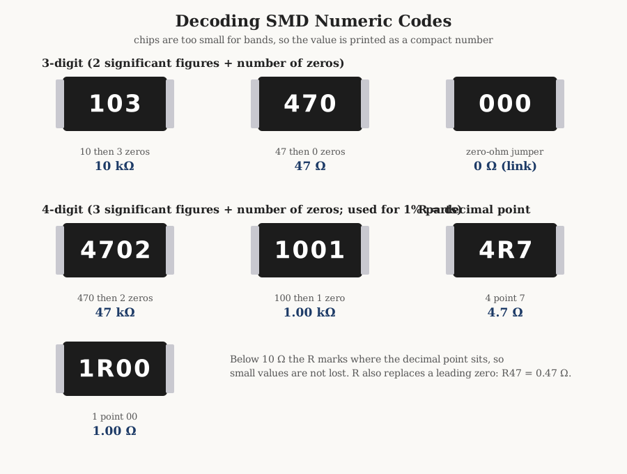
The most common mark is three digits, read exactly like the color code’s two-significant-figures-plus-multiplier: the first two digits are the significant figures, and the third digit is the number of zeros (equivalently, the power-of-ten multiplier). So 103 is 10 followed by 3 zeros = 10 000 Ω = 10 kΩ; 472 is 47 followed by 2 zeros = 4 700 Ω = 4.7 kΩ; 470 is 47 followed by no zeros = 47 Ω (not 470 Ω — the final 0 is the multiplier, ×10⁰). Figure 6 lays out the anatomy alongside the four-digit and decimal-point variants.
6.4.2 The four-digit code
Precision (±1%) chips need three significant figures, so they use a four-digit mark: the first three digits are significant figures and the fourth is the number of zeros. So 4702 is 470 followed by 2 zeros = 47 000 Ω = 47 kΩ; 1001 is 100 followed by 1 zero = 1.00 kΩ; 2200 is 220 followed by no zeros = 220 Ω. The scheme mirrors the three-digit code with one more figure, and the leading three digits are, of course, drawn from the E96/E192 ladders.
6.4.3 The R decimal notation
Neither code can express a value below 10 Ω, because there are no significant figures left of the decimal point. The fix is the letter R, which stands in for a decimal point. So 4R7 is 4.7 Ω, 0R5 or R50 is 0.5 Ω, and R47 is 0.47 Ω; in the four-digit world 1R00 is 1.00 Ω and 12R4 is 12.4 Ω. The R is placed exactly where the decimal point belongs, so it never gets lost the way a printed dot would. (On some parts a letter M or L is used the same way for milliohm-scale values, but R is by far the most common.)
6.4.4 The zero-ohm jumper
A resistor marked 000, or simply 0, is a zero-ohm jumper — a wire link in resistor’s clothing. It exists so that automated pick-and-place machinery can install a jumper with the same equipment that installs resistors, letting a board be wired or re-wired by loading a component rather than by cutting a trace. It has no value to decode; the mark is telling you it is a link, typically rated for a fraction of an amp.
6.4.5 The EIA-96 code for 1% chips
The smallest 1% chips ran into a problem: even a four-digit mark is hard to print legibly on an 0402 body. The industry’s answer, EIA-96, is a clever compression that squeezes a three-significant-figure value plus a multiplier into just three characters — two digits and a letter. The two digits are a code, 01 to 96, that looks up one of the 96 E96 values, and the letter is the multiplier. Figure 7 shows a real 0603 chip carrying the mark 01B, and Figure 8 unpacks the system.
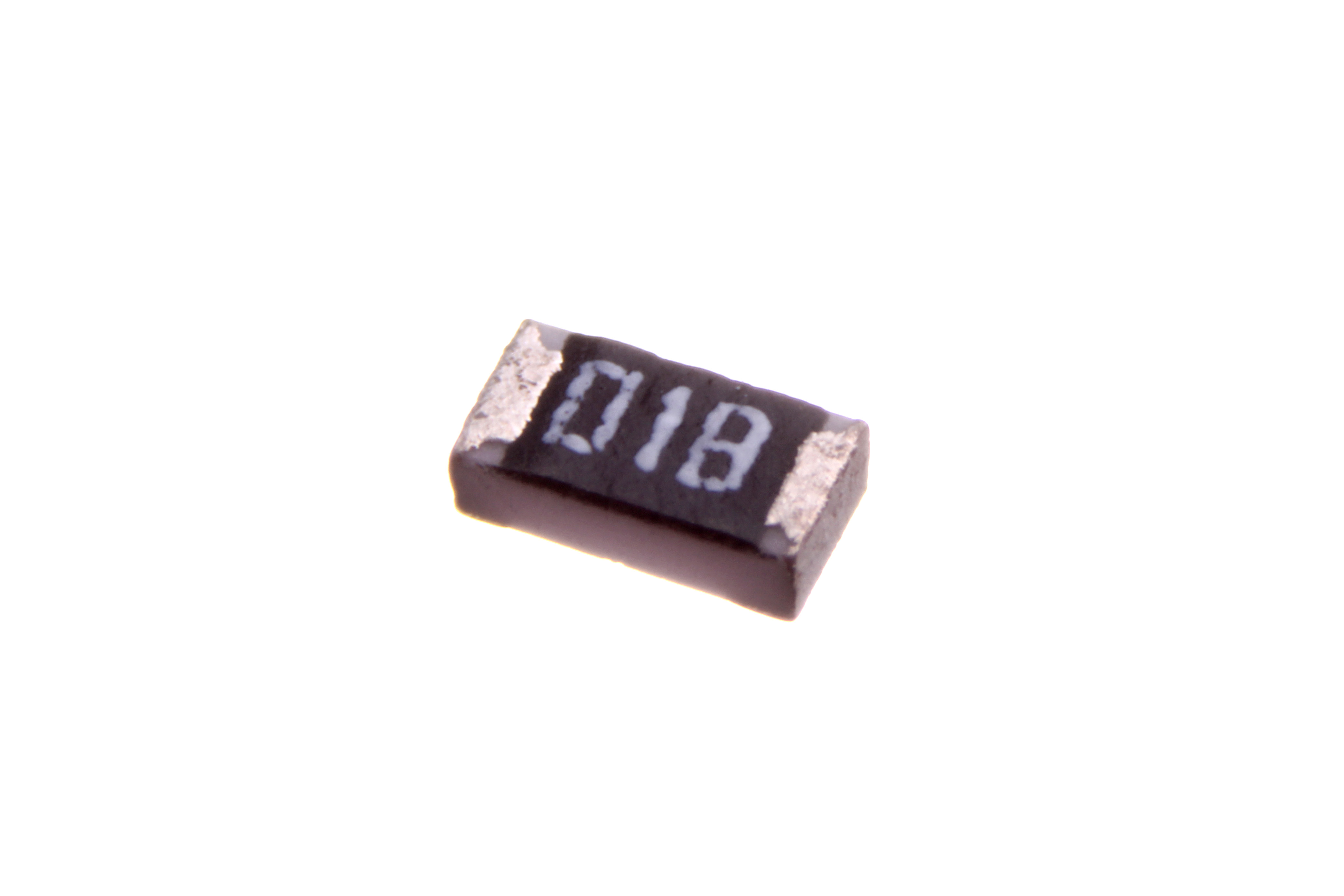
The genius of the scheme is that the two-digit code is not the value’s first figures — it is an index into the E96 table. Code 01 does not mean “10,” it means “the first E96 value,” which is 100; code 10 means “the tenth E96 value,” 124; code 49 is 316, code 50 is 324, and code 96 is 976. The letter then scales by a power of ten. So a chip marked 01B is the 1st E96 value (100) times B (×10) = 1.00 kΩ; a chip marked 68C is the 68th E96 value (499) times C (×100) = 49.9 kΩ.
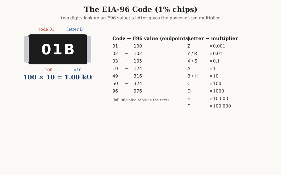
The letter multipliers are:
Table 5 — The letter multipliers are
| Letter | Multiplier | Letter | Multiplier | |
|---|---|---|---|---|
| Z | ×0.001 | B or H | ×10 | |
| Y or R | ×0.01 | C | ×100 | |
| X or S | ×0.1 | D | ×1 000 | |
| A | ×1 | E | ×10 000 | |
| F | ×100 000 |
And the two-digit code to value lookup — the heart of EIA-96 — runs the full length of the E96 ladder:
Table 6 — length of the E96 ladder
| 01=100 | 02=102 | 03=105 | 04=107 | 05=110 | 06=113 | 07=115 | 08=118 | 09=121 | 10=124 | 11=127 | 12=130 |
| 13=133 | 14=137 | 15=140 | 16=143 | 17=147 | 18=150 | 19=154 | 20=158 | 21=162 | 22=165 | 23=169 | 24=174 |
| 25=178 | 26=182 | 27=187 | 28=191 | 29=196 | 30=200 | 31=205 | 32=210 | 33=215 | 34=221 | 35=226 | 36=232 |
| 37=237 | 38=243 | 39=249 | 40=255 | 41=261 | 42=267 | 43=274 | 44=280 | 45=287 | 46=294 | 47=301 | 48=309 |
| 49=316 | 50=324 | 51=332 | 52=340 | 53=348 | 54=357 | 55=365 | 56=374 | 57=383 | 58=392 | 59=402 | 60=412 |
| 61=422 | 62=432 | 63=442 | 64=453 | 65=464 | 66=475 | 67=487 | 68=499 | 69=511 | 70=523 | 71=536 | 72=549 |
| 73=562 | 74=576 | 75=590 | 76=604 | 77=619 | 78=634 | 79=649 | 80=665 | 81=681 | 82=698 | 83=715 | 84=732 |
| 85=750 | 86=768 | 87=787 | 88=806 | 89=825 | 90=845 | 91=866 | 92=887 | 93=909 | 94=931 | 95=953 | 96=976 |
Those values are exactly the E96 series (three-figure preferred numbers), which is why the table is worth keeping: it is simultaneously the EIA-96 code lookup and the full list of standard 1% values.
6.4.6 Telling which scheme a chip uses
Faced with an unknown chip, decode by character count and content. Two characters that are digit-digit are unusual (some very-low-value marks); three characters are either a plain three-digit code (all digits, e.g. 103) or an EIA-96 code (two digits then a letter, e.g. 01B) — the trailing letter is the tell. Four characters, all digits is the four-digit ±1% code (4702); four characters with an embedded R is the decimal notation (1R00, 12R4). A stray letter that is not R and sits at the end points to EIA-96; an R inside the number points to the decimal notation. When two readings are plausible, the tie-breaker is the same as for the color code: the decoded value should be a standard E-series number, and a 1% chip small enough to carry EIA-96 will use it.
One case defeats every decoder: the unmarked chip. Below the 0402 case size, and on many 0402 parts, there is simply no printable area, so the resistor carries no mark at all — a plain black or grey rectangle. The value cannot be read from the part; it lives only in the reel label, the pick-and-place feeder assignment, and the bill of materials. The lesson for anyone reworking a dense board by hand is blunt: once an unmarked chip is off the board and out of its reel, its value is lost, and the only ways to recover it are to measure it with an ohmmeter (out of circuit) or to trace it back to the design files. This is a quiet argument for keeping small-value parts on their reels until the moment of placement, and for never mixing loose unmarked chips of different values in one dish.
6.5 Letter codes in part numbers and printed marks
Beyond the bands and chip marks, resistors carry letter codes in their full part numbers and, occasionally, printed alongside the value. Two sets matter.
6.5.1 Tolerance letters
A single letter after the value states the tolerance, and this convention appears on data sheets, in part numbers, and sometimes on the body of larger parts (a wirewound marked “100R J” is 100 Ω ±5%). The standard letters are:
Table 7 — marked "100R J" is 100 Ω ±5%). The standard letters are
| Letter | Tolerance | Letter | Tolerance | |
|---|---|---|---|---|
| B | ±0.1% | G | ±2% | |
| C | ±0.25% | J | ±5% | |
| D | ±0.5% | K | ±10% | |
| F | ±1% | M | ±20% |
Two of these — K and M — are a notorious trap, because the same letters are also the SI prefixes kilo and mega. Context resolves it: 1K5 means 1.5 kΩ (K as a decimal-point-and-multiplier, like R but for kilohms), whereas 1K5 K would be 1.5 kΩ at ±10% tolerance. In the compact value notation, R, K, and M all double as decimal points at the ohm, kilohm, and megohm scales: 4R7 = 4.7 Ω, 4K7 = 4.7 kΩ, 4M7 = 4.7 MΩ. The tolerance letter, when present, is the last character and separated in spirit from the value.
6.5.2 Tempco letters and date codes
Temperature coefficient is usually given in the part number by a letter or a short code that varies from manufacturer to manufacturer — there is no single universal tempco-letter standard as clean as the tolerance table, so the data sheet governs. A common industrial convention uses letters keyed to ppm/°C bands (for example a maker might assign a letter to “±100 ppm,” another to “±50 ppm,” another to “±25 ppm”), and precision houses print the ppm figure outright. When a design is tempco-sensitive, read the coefficient from the specific part number’s decoder in its data sheet rather than trusting a generic letter chart.
Finally, larger resistors sometimes carry a date or lot code — a two- to four-character stamp giving the year and week of manufacture, or a batch identifier. It is not part of the electrical value and should never be mistaken for one; if a mark does not decode to a sensible resistance, suspect a date or lot code (or a manufacturer’s house marking) before assuming the part is exotic.
6.6 How to read any resistor
The whole volume collapses into a short decision procedure. Faced with a resistor, first ask banded or printed?
If it is a banded axial part, orient it: find the tolerance band (gold or silver, or the lone band separated by the wider gap) and put it on the right; if both ends look similar, remember that gold and silver are never a first band. Then count the bands. Four bands: two digits, a multiplier, a tolerance. Five bands: three digits, a multiplier, a tolerance. Six bands: add a tempco. Read the digit colors as numbers, apply the multiplier, attach the tolerance — and sanity-check that the result is a standard E-series value; if it is not, you have misread a color or the orientation.
If it is a printed chip, decode by the character pattern. Three digits, all numeric: two significant figures plus a count of zeros (103 = 10 kΩ). Four digits, all numeric: three significant figures plus a count of zeros (4702 = 47 kΩ). Two digits followed by a letter: EIA-96 — look up the two-digit code in the E96 table and scale by the letter (01B = 100 × 10 = 1.00 kΩ). An R (or K or M) inside the number is a decimal point (4R7 = 4.7 Ω). A bare 0 or 000 is a zero-ohm jumper. When a code is ambiguous, the standard-value cross-check settles it, exactly as for the bands.
Those two branches read every fixed resistor in general use. The complete lookup apparatus — the color-code table, the E6-through-E192 value lists, the full EIA-96 and SMD code tables, and the tolerance and tempco letter charts, all in one place for the bench — is collected in the reference volume; this volume was the lesson, and the reference is the wall chart.
Comments (0)