Resistors · Volume 14
Reference: Tables, Codes, and Further Reading
14.1 How to use this volume
The thirteen volumes before this one told the story of the resistor: what it is, where its ohms come from, how it is built, how it fails, and where the interesting parts hide. This one is the lookup apparatus that story leaves behind. It is deliberately thin on prose and thick on tables, arranged so that a working engineer can find a number, decode a marking, or check a formula without reading a paragraph to get there. Everything here has been reproduced against the governing standards — IEC 60062 for markings, IEC 60063 for the preferred-value series, IEC 60115 for the parts themselves — and against manufacturer literature. Where a value is a historical convention rather than a rounding (the E-series is riddled with these), the convention is what appears; do not re-derive these tables by rounding a logarithm, because the standards do not.
Each section opens with a sentence or two of orientation and then hands over to the table. The figures are reference cards meant to be printed and pinned over a bench. Cross-references point back into the narrative volumes where a term is developed at length.
Glossary
The vocabulary of the whole dive, alphabetised. Terms in bold within a definition have their own entry.
Table 1 — Glossary
| Term | Definition |
|---|---|
| Bulk-metal foil | Precision resistor technology using a cold-rolled resistance-alloy foil cemented to a substrate; the substrate’s expansion is engineered to cancel the foil’s TCR, giving the lowest tempco and best long-term stability of any type (Vol 8). |
| Derating | The deliberate operation of a part below its rated maximum — chiefly power — as ambient temperature rises, following the manufacturer’s derating curve to zero at the maximum body temperature (Vol 9). |
| E-series | The IEC 60063 geometric ladders of preferred values (E6, E12, E24, E48, E96, E192), spaced so their tolerance bands just meet across a decade. |
| Excess noise | Current-dependent 1/f noise generated above the unavoidable Johnson noise, arising from the granular conduction of composition and thick-film elements; quoted in µV per volt applied, or dB (Vol 3). |
| Gauge factor | For a strain gauge, the fractional change in resistance per unit strain, (ΔR/R)/ε; about 2 for a metal-foil gauge (Vol 11). |
| Johnson–Nyquist noise | The unavoidable thermal noise voltage of any resistance, Vn = √(4kTRB), independent of material or current; the noise floor every resistor shares (Vol 3). |
| Kelvin (4-wire) connection | A measurement wiring that carries current through one pair of leads and senses voltage through a separate pair, removing lead and contact resistance from the reading; the basis of the sense terminals on precision shunts (Vols 8, 11). |
| Multiplier | The power-of-ten scaling band or letter in a marking, applied to the significant figures to give the value (Vols 6, this vol). |
| Parasitics | The unwanted reactive elements of a real resistor — series inductance L and shunt capacitance C — that make its impedance deviate from R at high frequency (Vol 3). |
| Preferred value | One of the standardised nominal resistances of an E-series; stocking only these values covers every decade with minimum overlap. |
| PTC / NTC | Positive / negative temperature coefficient: resistance that rises / falls with temperature. Metals are PTC; carbon, semiconductors, and thermistors can be either (Vols 2, 11). |
| Resistance (R) | The ratio of voltage across a component to current through it, V/I, in ohms (Ω); the defining property (Vol 1). |
| Resistivity (ρ) | The material’s own resistance, independent of shape, in Ω·m; R = ρL/A (Vol 2). |
| Self-resonant frequency (SRF) | The frequency at which a resistor’s series L and shunt C resonate; above it the part no longer behaves as a resistance (Vol 3). |
| Sheet resistance (Rs) | The resistance of a square of thin film, ρ/t, in ohms per square (Ω/□); geometry-independent for any square, the unit in which film resistors are designed and trimmed (Vol 2). |
| Shunt | A low-value, high-accuracy resistor placed in a current path so the voltage across it measures the current; usually Kelvin-connected (Vol 11). |
| Stability | The permanence of the value over time, load, humidity, and thermal cycling, quoted as a maximum drift (e.g. ±0.25% over 1000 h at rated load); distinct from tolerance, which is the value at manufacture (Vol 9). |
| Temperature coefficient (TCR) | The fractional change of resistance per degree, in ppm/°C; the headline spec separating precision from commodity parts (Vol 3). |
| Tolerance | The permitted deviation of the value from nominal at manufacture, as a percentage; marked by band, letter, or the implied E-series (Vols 3, 6). |
| Voltage coefficient (VCR) | The fractional change of resistance per volt applied, in ppm/V; a nonlinearity of high-value thick-film and composition parts (Vol 3). |
| Wirewound | A resistor made of resistance wire wound on a former; the type for high power and high precision, but with the most series inductance (Vol 8). |
14.2 Color-code reference
The four-, five-, and six-band axial code of IEC 60062. Read from the band nearest an end. The first bands are significant figures, the next is the multiplier, then tolerance, and on a six-band part a final temperature-coefficient band. On a four-band part the first two bands are digits; on five- and six-band parts the first three are. The digit colours (black = 0 through white = 9) are the spine of the whole system and are identical in every column that carries a digit.
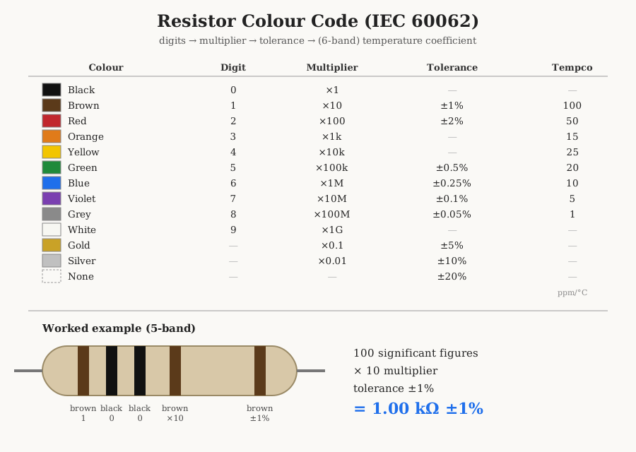
Table 2 — Color-code reference
| Colour | Digit | Multiplier | Tolerance | Tempco (ppm/°C) |
|---|---|---|---|---|
| Black | 0 | ×1 | — | — |
| Brown | 1 | ×10 | ±1% | 100 |
| Red | 2 | ×100 | ±2% | 50 |
| Orange | 3 | ×1 000 | — | 15 |
| Yellow | 4 | ×10 000 | — | 25 |
| Green | 5 | ×100 000 | ±0.5% | 20 |
| Blue | 6 | ×1 000 000 | ±0.25% | 10 |
| Violet | 7 | ×10 000 000 | ±0.1% | 5 |
| Grey | 8 | ×100 000 000 | ±0.05% | 1 |
| White | 9 | ×1 000 000 000 | — | — |
| Gold | — | ×0.1 | ±5% | — |
| Silver | — | ×0.01 | ±10% | — |
| None | — | — | ±20% | — |
Worked example: a five-band part banded brown–black–black–brown–brown reads 1, 0, 0 as significant figures = 100, ×10 multiplier = 1 000, tolerance brown = ±1%, i.e. 1.00 kΩ ±1%. The same three digits with a red fourth band (×100) would be 10.0 kΩ. The gold and silver multipliers exist to reach sub-ohm and single-ohm values (a gold third band on brown–black is 1.0 Ω), and the same two colours reappear as the ±5% and ±10% tolerances that dominate general-purpose stock.
14.3 SMD-code reference
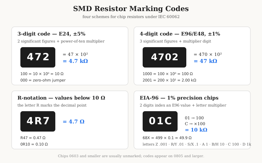
Chip resistors are too small for bands, so the value is printed as digits (on parts down to 0805; the 0603 and smaller are usually blank). Three coding schemes are in use, all defined or referenced by IEC 60062.
Three-digit code (E24, ±5%). Two significant figures followed by a power-of-ten multiplier digit. 472 = 47 × 10² = 4.7 kΩ. 100 = 10 × 10⁰ = 10 Ω. 000 or 0 marks a zero-ohm jumper.
Four-digit code (E96/E48, ±1%). Three significant figures followed by one multiplier digit. 4702 = 470 × 10² = 47 kΩ. 1000 = 100 × 10⁰ = 100 Ω.
R-notation (values below 10 Ω, either scheme). The letter R marks the decimal point and replaces the multiplier. 4R7 = 4.7 Ω; R47 = 0.47 Ω; 0R10 = 0.10 Ω. On very-low-value sense resistors an L or M may be substituted for milliohm markings in some ranges.
EIA-96 code (1% chips). Precision chips too small for four digits use a two-digit code plus a letter: the two digits index the E96 value in the table below; the letter is a multiplier. 01C = 100 × 100 = 10 kΩ. 68X = 499 × 0.1 = 49.9 Ω.
14.3.1 EIA-96 letter multipliers
Table 3 — EIA-96 letter multipliers
| Letter | Multiplier | Letter | Multiplier | |
|---|---|---|---|---|
| Z | ×0.001 | B or H | ×10 | |
| Y or R | ×0.01 | C | ×100 | |
| X or S | ×0.1 | D | ×1 000 | |
| A | ×1 | E | ×10 000 | |
| F | ×100 000 |
14.3.2 EIA-96 code → value (all 96 codes)
Table 4 — EIA-96 code → value (all 96 codes)
| Code | Val | Code | Val | Code | Val | Code | Val |
|---|---|---|---|---|---|---|---|
| 01 | 100 | 25 | 178 | 49 | 316 | 73 | 562 |
| 02 | 102 | 26 | 182 | 50 | 324 | 74 | 576 |
| 03 | 105 | 27 | 187 | 51 | 332 | 75 | 590 |
| 04 | 107 | 28 | 191 | 52 | 340 | 76 | 604 |
| 05 | 110 | 29 | 196 | 53 | 348 | 77 | 619 |
| 06 | 113 | 30 | 200 | 54 | 357 | 78 | 634 |
| 07 | 115 | 31 | 205 | 55 | 365 | 79 | 649 |
| 08 | 118 | 32 | 210 | 56 | 374 | 80 | 665 |
| 09 | 121 | 33 | 215 | 57 | 383 | 81 | 681 |
| 10 | 124 | 34 | 221 | 58 | 392 | 82 | 698 |
| 11 | 127 | 35 | 226 | 59 | 402 | 83 | 715 |
| 12 | 130 | 36 | 232 | 60 | 412 | 84 | 732 |
| 13 | 133 | 37 | 237 | 61 | 422 | 85 | 750 |
| 14 | 137 | 38 | 243 | 62 | 432 | 86 | 768 |
| 15 | 140 | 39 | 249 | 63 | 442 | 87 | 787 |
| 16 | 143 | 40 | 255 | 64 | 453 | 88 | 806 |
| 17 | 147 | 41 | 261 | 65 | 464 | 89 | 825 |
| 18 | 150 | 42 | 267 | 66 | 475 | 90 | 845 |
| 19 | 154 | 43 | 274 | 67 | 487 | 91 | 866 |
| 20 | 158 | 44 | 280 | 68 | 499 | 92 | 887 |
| 21 | 162 | 45 | 287 | 69 | 511 | 93 | 909 |
| 22 | 165 | 46 | 294 | 70 | 523 | 94 | 931 |
| 23 | 169 | 47 | 301 | 71 | 536 | 95 | 953 |
| 24 | 174 | 48 | 309 | 72 | 549 | 96 | 976 |
14.4 E-series reference
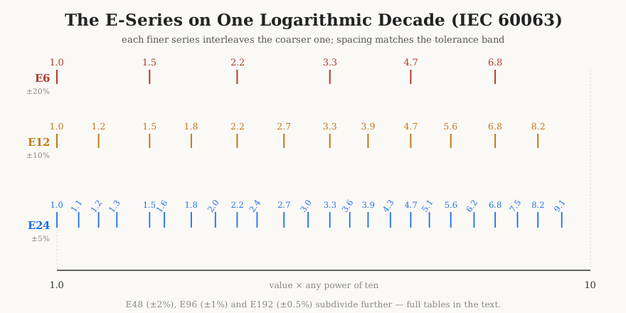
The preferred values of IEC 60063. Each series divides a decade into a geometric ladder whose spacing matches a tolerance grade: E6 for ±20%, E12 for ±10%, E24 for ±5%, E48 for ±2%, E96 for ±1%, E192 for ±0.5% and tighter. The values listed below are the one-decade set; multiply by any power of ten for other decades (1.5 → 15, 150, 1.5 k, and so on).
14.4.1 E6 (±20%) and E12 (±10%)
Table 5 — E6 (±20%) and E12 (±10%)
| E6 | 1.0 | 1.5 | 2.2 | 3.3 | 4.7 | 6.8 |
|---|---|---|---|---|---|---|
| E12 | 1.0, 1.2 | 1.5, 1.8 | 2.2, 2.7 | 3.3, 3.9 | 4.7, 5.6 | 6.8, 8.2 |
14.4.2 E24 (±5%)
Table 6 — E24 (±5%)
| 1.0 | 1.1 | 1.2 | 1.3 | 1.5 | 1.6 | 1.8 | 2.0 | 2.2 | 2.4 | 2.7 | 3.0 |
| 3.3 | 3.6 | 3.9 | 4.3 | 4.7 | 5.1 | 5.6 | 6.2 | 6.8 | 7.5 | 8.2 | 9.1 |
14.4.3 E48 (±2%)
Table 7 — E48 (±2%)
| 1.00 | 1.05 | 1.10 | 1.15 | 1.21 | 1.27 | 1.33 | 1.40 |
| 1.47 | 1.54 | 1.62 | 1.69 | 1.78 | 1.87 | 1.96 | 2.05 |
| 2.15 | 2.26 | 2.37 | 2.49 | 2.61 | 2.74 | 2.87 | 3.01 |
| 3.16 | 3.32 | 3.48 | 3.65 | 3.83 | 4.02 | 4.22 | 4.42 |
| 4.64 | 4.87 | 5.11 | 5.36 | 5.62 | 5.90 | 6.19 | 6.49 |
| 6.81 | 7.15 | 7.50 | 7.87 | 8.25 | 8.66 | 9.09 | 9.53 |
14.4.4 E96 (±1%)
Table 8 — E96 (±1%)
| 1.00 | 1.02 | 1.05 | 1.07 | 1.10 | 1.13 | 1.15 | 1.18 |
| 1.21 | 1.24 | 1.27 | 1.30 | 1.33 | 1.37 | 1.40 | 1.43 |
| 1.47 | 1.50 | 1.54 | 1.58 | 1.62 | 1.65 | 1.69 | 1.74 |
| 1.78 | 1.82 | 1.87 | 1.91 | 1.96 | 2.00 | 2.05 | 2.10 |
| 2.15 | 2.21 | 2.26 | 2.32 | 2.37 | 2.43 | 2.49 | 2.55 |
| 2.61 | 2.67 | 2.74 | 2.80 | 2.87 | 2.94 | 3.01 | 3.09 |
| 3.16 | 3.24 | 3.32 | 3.40 | 3.48 | 3.57 | 3.65 | 3.74 |
| 3.83 | 3.92 | 4.02 | 4.12 | 4.22 | 4.32 | 4.42 | 4.53 |
| 4.64 | 4.75 | 4.87 | 4.99 | 5.11 | 5.23 | 5.36 | 5.49 |
| 5.62 | 5.76 | 5.90 | 6.04 | 6.19 | 6.34 | 6.49 | 6.65 |
| 6.81 | 6.98 | 7.15 | 7.32 | 7.50 | 7.68 | 7.87 | 8.06 |
| 8.25 | 8.45 | 8.66 | 8.87 | 9.09 | 9.31 | 9.53 | 9.76 |
E192 (±0.5%, ±0.25%, ±0.1%) adds a further 96 interleaved values to make 192 per decade; it is not reproduced in full here — it is the E96 set with an intermediate value inserted between each pair, and is used only for the highest-precision metal-film and foil parts. Its first values run 1.00, 1.01, 1.02, 1.04, 1.05, 1.06, 1.07, 1.09, …
14.5 Tolerance and temperature-coefficient letter codes
On body-printed and datasheet part numbers the tolerance and tempco are given as single letters rather than bands. The tolerance set is the IEC 60062 standard; the tempco letters follow the common industry (EIA) assignment used by the major film-resistor makers.
Table 9 — Tolerance and temperature-coefficient letter codes
| Tolerance letter | Tolerance | Tempco letter | TCR (ppm/°C) | |
|---|---|---|---|---|
| B | ±0.1% | K | ±250 | |
| C | ±0.25% | J | ±100 | |
| D | ±0.5% | H | ±50 | |
| F | ±1% | G | ±30 | |
| G | ±2% | F | ±25 | |
| J | ±5% | E | ±15 | |
| K | ±10% | D | ±10 | |
| M | ±20% | C | ±5 |
Two traps travel with these. First, the letters G, J, and K appear in both columns with different meanings — G is ±2% tolerance but ±30 ppm/°C tempco — so context (which field of the part number) decides. Second, older MIL and some Asian schemes assign the tempco letters differently; always confirm against the specific datasheet rather than assuming the table above.
14.6 Standard power ratings and SMD sizes
Through-hole resistors come in a fixed ladder of power ratings; the value quoted is the maximum continuous dissipation at a stated ambient (usually 70 °C), and must be derated above it (Vol 9). Surface-mount chips are specified by a size code that is simultaneously a physical footprint and, by convention, a power rating.
Table 10 — Standard power ratings and SMD sizes
| Rating | Watts | Typical body / use |
|---|---|---|
| ⅒ W | 0.10 | small signal, axial and 0805 chip |
| ⅛ W | 0.125 | most common through-hole signal part |
| ¼ W | 0.25 | general-purpose workhorse |
| ½ W | 0.50 | higher-dissipation signal |
| 1 W | 1.0 | small power |
| 2 W | 2.0 | power, often metal-oxide film |
| 3 W, 5 W, 10 W, 25 W | 3–25 | wirewound, aluminium-clad chassis-mount |
14.6.1 SMD chip sizes → dimensions → power
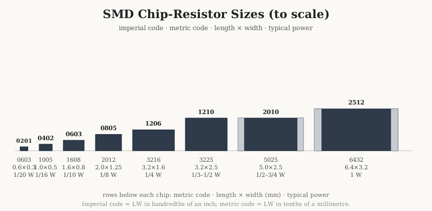
The size code is the two body dimensions. Imperial codes give length and width in hundredths of an inch; metric codes give the same in tenths of a millimetre. Power ratings are the industry-typical values and vary by series and technology.
Table 11 — SMD chip sizes → dimensions → power
| Imperial | Metric | L × W (mm) | Typical power |
|---|---|---|---|
| 0201 | 0603 | 0.6 × 0.3 | 1/20 W (0.05 W) |
| 0402 | 1005 | 1.0 × 0.5 | 1/16 W (0.063 W) |
| 0603 | 1608 | 1.6 × 0.8 | 1/10 W (0.10 W) |
| 0805 | 2012 | 2.0 × 1.25 | 1/8 W (0.125 W) |
| 1206 | 3216 | 3.2 × 1.6 | 1/4 W (0.25 W) |
| 1210 | 3225 | 3.2 × 2.5 | 1/3–1/2 W |
| 2010 | 5025 | 5.0 × 2.5 | 1/2–3/4 W |
| 2512 | 6432 | 6.4 × 3.2 | 1 W |
14.7 Resistivity and material temperature coefficient
The material constants underlying every resistor and every wire, at 20 °C. Resistivity ρ sets how many ohms a given geometry yields (R = ρL/A); the material TCR sets how far the value drifts with temperature. Conductors sit near 10⁻⁸ Ω·m with large positive TCR; the resistance alloys sit two decades higher with TCR tuned toward zero — the whole point of alloying (Vol 2).
Table 12 — Resistivity and material temperature coefficient
| Material | ρ at 20 °C (Ω·m) | Material TCR (ppm/°C) | Role |
|---|---|---|---|
| Silver | 1.59 × 10⁻⁸ | +3 800 | best metallic conductor |
| Copper | 1.68 × 10⁻⁸ | +3 900 | the workhorse conductor |
| Gold | 2.44 × 10⁻⁸ | +3 400 | corrosion-proof contacts |
| Aluminium | 2.65 × 10⁻⁸ | +4 300 | light-weight conductor |
| Tungsten | 5.6 × 10⁻⁸ | +4 500 | lamp filaments |
| Nichrome (Ni80/Cr20) | ~1.0–1.5 × 10⁻⁶ | +100 to +400 | heaters, wirewound resistors |
| Constantan (Cu55/Ni45) | ~4.9 × 10⁻⁷ | ±20 | near-zero-tempco alloy, strain gauges |
| Manganin (Cu/Mn/Ni) | ~4.8 × 10⁻⁷ | ±15 | precision shunts, standards |
| Evanohm (Ni/Cr/Al/Cu) | ~1.3 × 10⁻⁶ | ±5 | finest wirewound and foil parts |
| Carbon (graphite, in-plane) | ~3–60 × 10⁻⁵ | −200 to −800 | composition and carbon-film elements |
14.8 Master specs by resistor type
The consolidated comparison of the fixed-resistor families treated in Volumes 7 and 8, at typical commercial grades. Every figure is representative, not a limit; premium sub-grades of each type reach well beyond the numbers shown.
Table 13 — Master specs by resistor type
| Type | Tolerance | TCR (ppm/°C) | Power range | Noise | Stability | Rel. cost | Where it wins |
|---|---|---|---|---|---|---|---|
| Carbon composition | ±5 to ±20% | −800 to +1000 | ⅛–2 W | high | poor (drift, humidity) | low | pulse/surge energy handling |
| Carbon film | ±2 to ±5% | −200 to −500 | ⅛–2 W | moderate | fair | lowest | legacy general purpose |
| Metal film (thin) | ±0.1 to ±1% | ±5 to ±100 | ⅒–1 W | low | good | moderate | precision signal work |
| Metal-oxide film | ±1 to ±5% | ±300 | ½–5 W | moderate | good | low | higher-temperature power |
| Thick film (chip) | ±1 to ±5% | ±100 to ±250 | 1/20–1 W | moderate–high | good | lowest (SMD) | volume SMD, everything |
| Thin film (chip) | ±0.01 to ±0.5% | ±5 to ±50 | 1/20–½ W | low | very good | high | precision SMD, ratio nets |
| Wirewound (power) | ±1 to ±5% | ±20 to ±300 | 1–1000 W | very low | good | moderate | high power, low inductance grades |
| Wirewound (precision) | ±0.01 to ±0.1% | ±3 to ±10 | ¼–2 W | very low | excellent | high | standards, instrumentation |
| Bulk-metal foil | ±0.001 to ±0.05% | ±0.2 to ±2 | ⅒–½ W | very low | best available | highest | metrology, reference dividers |
14.9 Formula cheat-sheet
The equations used across the dive, gathered in one place. Symbols: V volts, I amps, R ohms, P watts, k Boltzmann’s constant 1.38 × 10⁻²³ J/K, T temperature in kelvin, B noise bandwidth in hertz, C capacitance in farads, t time in seconds.
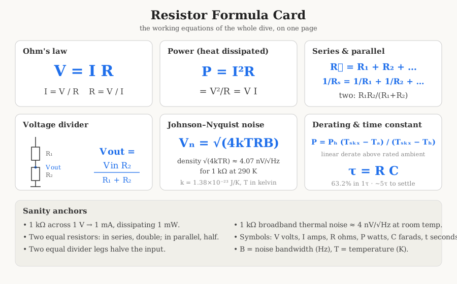
Table 14 — Formula cheat-sheet
| Quantity | Formula | Notes |
|---|---|---|
| Ohm’s law | V = I × R | and I = V/R, R = V/I |
| Power dissipated | P = I²R = V²/R = V × I | the heat the part must shed |
| Series resistance | R = R₁ + R₂ + … + Rₙ | values add; total ≥ largest |
| Parallel resistance | 1/R = 1/R₁ + 1/R₂ + … | total ≤ smallest |
| Two in parallel | R = R₁R₂ / (R₁ + R₂) | the product-over-sum shortcut |
| Voltage divider | Vout = Vin × R₂ / (R₁ + R₂) | R₂ is the lower (output) leg |
| Johnson–Nyquist noise | Vn = √(4kTRB) | RMS thermal noise; ≈ 0.13 µV for 1 kΩ, 1 Hz, 290 K → scales as √(RB) |
| Noise density | Vn/√B = √(4kTR) | ≈ 4.07 nV/√Hz for 1 kΩ at 290 K |
| Power derating | Pallow = Prated × (Tmax − Tamb)/(Tmax − Trated) | linear derating above the rated ambient |
| RC time constant | τ = R × C | charges/discharges to 63.2% in one τ; ~5τ to settle |
Quick sanity anchors: a 1 kΩ across 1 V passes 1 mA and dissipates 1 mW; two equal resistors in parallel are half of one; two equal in series are double; a divider of two equal legs halves the input; a 1 kΩ resistor’s broadband thermal noise is about 4 nV/√Hz at room temperature.
14.10 Standards and further reading
The documents that govern the resistor, and the books and application notes that explain it. Standard numbers and titles below were confirmed against the issuing bodies’ catalogues.
14.10.1 Governing standards
Table 15 — Governing standards
| Standard | Scope |
|---|---|
| IEC 60062 | Marking codes for resistors and capacitors — colour bands, the R-notation, tolerance and tempco letters, EIA-96. |
| IEC 60063 | Preferred number series for resistors and capacitors — the E3…E192 ladders. |
| IEC 60115 (series) | Fixed resistors for use in electronic equipment — the generic specification and its sectional parts (60115-1 general, with parts for film, power, chip, and network types). |
| EIA-96 (EIA/ECA) | The two-digit-plus-letter marking for 1% chip resistors, referenced by IEC 60062. |
| MIL-PRF-55182 | Fixed film resistors, established reliability (the “RN”/“RL” style precision film parts). |
| MIL-PRF-39007 / -22684 / -55342 | Wirewound (established reliability), fixed film (non-ER), and chip resistors respectively. |
| MIL-STD-202 | Test methods for electronic component parts (thermal shock, life, moisture) invoked by the above. |
14.10.2 Recommended books
- Paul Horowitz and Winfield Hill, The Art of Electronics, 3rd ed. (Cambridge University Press, 2015) — the standard reference; its opening chapter treats the resistor, dividers, and noise at exactly the working-engineer altitude of this dive.
- Charles A. Harper (ed.), Passive Electronic Component Handbook, 2nd ed. (McGraw-Hill) — encyclopaedic coverage of resistor, capacitor, and inductor construction and specification.
- Felix Zandman, Paul-René Simon, and Joseph Szwarc, Resistor Theory and Technology (SciTech/Vishay, 2001) — the definitive monograph on precision resistor physics, by the inventors of bulk-metal foil.
- Morris E. Levin (ed.), Resistors: A Guide to Characterization and Application — component-engineering perspective on selection and reliability.
14.10.3 Manufacturer application notes (real, checkable titles)
- Vishay, “Resistor Basics” and “Power Dissipation and Derating” technical notes; the Bulk Metal Foil technology papers (e.g. the VFR/Z-Foil series notes).
- Bourns, “Chip Resistor Application Notes” and the pulse/surge withstanding guides for its thick-film chip and current-sense lines.
- KOA Speer, “Understanding Resistor Derating” and the current-sensing / high-power thick-film application literature.
- TT Electronics (Welwyn/IRC), “Resistor Marking Codes” and pulse-load / high-voltage resistor application notes.
- Yageo and Panasonic general-purpose chip-resistor datasheets, for the canonical size-versus-power and TCR-versus-value tables reproduced above.
14.11 The resistor in one page
A resistor is a two-terminal part whose single job is to present a fixed, predictable opposition to current, converting the energy it takes into heat and storing none of it. That plainness — no reactance, no memory, the same value for a nanosecond pulse as for an hour of DC — is exactly why it is the most common component in electronics and the reference against which every other part is measured. Its value comes from a material’s resistivity shaped by geometry (R = ρL/A); its quality is measured not by that value but by how little the value moves — with temperature (TCR, in ppm/°C), with voltage (VCR), with time (stability), and by how little noise it adds above the unavoidable Johnson floor. Everything a datasheet says about a resistor is a way of quantifying one of those drifts, and everything a designer pays extra for is a smaller one. The value is chosen from the E-series, marked in bands or SMD code, held to a tolerance, rated for a power that must be derated in the heat, and built — from cheap carbon film to metrology-grade foil — in whatever technology buys the needed stability at the needed price.
This closes the Resistors dive, the third in the passive-components program. Its two companions treat the storing siblings: the Capacitors dive, on energy held in an electric field and the part that resists a change in voltage, and the Coils dive, on energy held in a magnetic field and the part that resists a change in current — both on research.fubsypoly.com, and both illuminating the resistor by contrast. The program continues with the coming Transformers dive, where two coils share a core and the resistor returns in a supporting role — damping, snubbing, bleeding, and setting the working points around the magnetics. The brake, the spring, the flywheel: with all three understood, the rest of electronics is their conversation.
Comments (0)