Resistors · Volume 10
Networks, Arrays, and the Potentiometer
10.1 When one number is not enough
Every volume up to this point has treated a resistor as a single fixed number: so many ohms, held to some tolerance, drifting by some ppm per degree. That is the right picture for the discrete part soldered one-per-footprint across a board. But two large families break the mold, and both are everywhere. The first puts several resistors into one body, not merely to save space but because resistors born on the same tiny chip of ceramic track one another far better than any two parts pulled from a bin ever could — the resistor network and array. The second makes the number adjustable, trading a fixed value for a shaft, a slider, or a digital register that moves a contact along a resistive track — the potentiometer and its cousins the rheostat, the trimmer, and the digital pot. This volume is about those two families: why they exist, how they are built, and where the engineering subtleties hide. The theme that unifies them is that a resistor is rarely interesting in isolation; it earns its keep in relation to another resistance, whether a matched twin on the same substrate or the two halves of a track split by a moving wiper.
10.2 Networks and arrays: matching beats density
10.2.1 Why several resistors share one chip
The obvious reason to package four or eight resistors together is board area: a single ten-pin package holds what would otherwise be eight discrete chips, and a machine places one part instead of eight. That matters in dense digital boards, but it is not the reason a precision engineer reaches for a network. The real reason is matching — the fact that resistors made side by side, in one firing, trimmed in one pass, on one slab of alumina are nearly identical to one another and, just as importantly, drift together.
Consider two ordinary 1% chip resistors from the same reel. Each is guaranteed within 1% of its marked value, so the ratio of the two could be off by nearly 2%. Warm the board and each drifts by its own temperature coefficient — say 100 ppm/°C — but nothing forces the two to drift by the same amount or even the same sign, so their ratio wanders as the temperature changes. Now take two resistors from a single network chip. Their absolute values may each be loose — a network is often specified only to ±1% or even ±2% absolute — but because they were deposited from the same paste, fired in the same oven, and trimmed on the same machine, the ratio between them is held to something like ±0.1% or better, and their temperature coefficients track to within a few ppm/°C of each other even when each one’s absolute tempco is ten times larger. The two resistors do not stop drifting; they drift in lockstep, and their ratio barely moves. That distinction — absolute tolerance versus ratio tolerance, and absolute TCR versus TCR tracking — is the whole value proposition of a precision network, and it is why a divider, a gain-setting pair, or a bridge built from one network outperforms the same circuit built from four hand-matched discretes.
The reason this matters is that an enormous number of analog circuits care only about a ratio of resistances, never their absolute value. A voltage divider’s output is set by the ratio of its two legs. An instrumentation or difference amplifier’s common-mode rejection depends on how well two resistor ratios match — a 0.1% mismatch in the four resistors of a classic difference amp limits common-mode rejection to roughly 66 dB, while a matched network pushes it far higher. The gain of a non-inverting stage is one plus a resistor ratio. In all of these, the absolute ohms can wander with temperature and age; as long as the ratio holds, the circuit holds. The network sells exactly that.
10.2.2 Isolated, bussed, and divider topologies
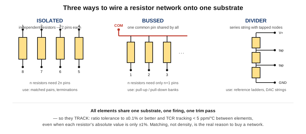
Inside the package the resistors can be wired three ways, and the choice determines both the pin count and the job the part is good for (Figure 2).
An isolated network is simply n independent resistors sharing a body but nothing electrically — each has its own two pins, so n resistors need 2n pins. This is the layout to buy when a circuit needs several resistors that must match but do not share a node: series terminators on a data bus, matched pairs for two identical gain stages, the four legs of a bridge. It is the most flexible and the most pin-hungry.
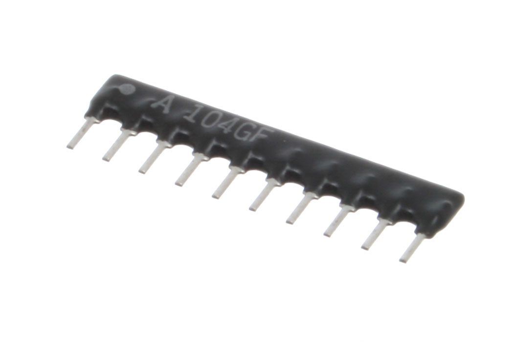
A bussed network ties one end of every resistor to a single common pin, so n resistors need only n + 1 pins. This is the workhorse for pull-up and pull-down banks: tie the common pin to the supply rail (or to ground) and each free pin becomes a pull-up (or pull-down) for one logic line. A bank of eight pull-ups on a data bus collapses from eight discretes and eight solder joints into one nine-pin SIP. The 100 kΩ part in Figure 1, marked with a leading “A”, is exactly this: nine resistors to a common bus.
A divider (or ladder) network wires the resistors in series with the junctions brought out as taps, so the part is a pre-built string of voltage dividers or a reference ladder. Because the taps are all cut from one resistive strip, the divider ratios are held to the network’s tight ratio tolerance — ideal for setting a row of reference thresholds, biasing a string of comparators, or feeding a resistor-string data converter.
10.2.3 Packages: from the SIP comb to the four-in-a-chip
Networks come in the same package spectrum as everything else, scaled by how many elements they hold. The SIP (single in-line package) is the leaded comb of Figure 1 — a flat molded body with all pins in one row on 0.1-inch (2.54 mm) centers, typically four to thirteen pins. It is cheap, easy to hand-solder, and the classic home for pull-up banks and terminator arrays. The DIP (dual in-line package) and its surface-mount sibling the SOIC put the elements between two rows of pins, echoing an IC footprint, which suits denser boards and lets a designer drop a resistor network into a socket-like footprint beside the logic it serves.
The surface-mount world shrinks all of this into the chip array: four (or two) resistors inside a single small body the size of an 0804 or 1206 chip, with terminations along the edges — the “convex” style with terminals on the long sides, or the “concave” style with castellated ends. A 0402×4 array packs four independent resistors into a footprint barely larger than a single 0805, and it is ubiquitous in phones and other dense consumer boards precisely because it saves both area and pick-and-place cycles. These commodity arrays are usually thick-film and sold for density rather than precision; the matched networks that exploit tracking are more often thin-film on the DIP/SOIC or specialized leaded packages, where the manufacturer can guarantee the tight ratio and tracking numbers.
10.2.4 The R-2R ladder: two values, one converter
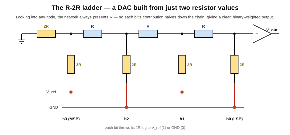
The most elegant use of a matched network is the R-2R ladder, the resistor structure at the heart of many digital-to-analog converters (DACs) and some analog-to-digital converters. Its charm is that it needs only two resistance values — some value R and its exact double 2R — arranged so that the network presents the same resistance R looking into every node. Because of that self-similarity, each successive bit’s contribution to the output is exactly half the previous bit’s, which is precisely the binary weighting a converter needs: the most-significant bit contributes half the full scale, the next a quarter, and so on down the chain (Figure 3).
The reason the R-2R ladder must be a matched network and not a handful of discretes is that a converter’s accuracy — its integral and differential nonlinearity (INL and DNL) — is set almost entirely by how well the ratio 2R:R holds across every rung. An 8-bit DAC needs its resistors matched to better than one part in 256 to stay monotonic; a 16-bit converter needs matching to a few parts per million. No bin of discrete resistors can hold that, but a thin-film ladder trimmed on one substrate can, which is why integrated DACs build their ladders on-chip and why precision R-2R networks are sold as standalone parts for building converters and programmable dividers. Here the network is not a convenience — it is the only way the circuit can exist at all.
10.3 The potentiometer
10.3.1 Three terminals, one moving contact
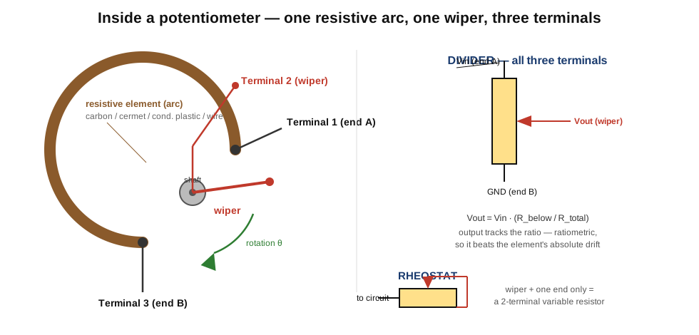
The potentiometer — “pot” on any bench — is the archetypal variable resistor, and its construction is simple enough to hold in the hand and understand at a glance (Figure 4). A resistive element is laid down as an arc (in a rotary pot) or a straight strip (in a slider), with a terminal brought out from each end. A wiper — a spring contact carried on a rotating shaft or a sliding carriage — presses against the element and can be moved to any point along it, and the wiper connects to a third terminal. That is the entire machine: two end terminals and a wiper, three connections in all.
What makes the pot useful is that the wiper divides the element into two resistances in series, and their split is set by the wiper’s position. Turn the shaft one way and the wiper sits near end A, so almost all of the element lies between the wiper and end B; turn it the other way and the split reverses. The total end-to-end resistance never changes — a 10 kΩ pot is always 10 kΩ from end to end — but the two pieces on either side of the wiper trade off continuously.
10.3.2 The divider and the rheostat: two ways to wire the same part
Precisely because it has three terminals, a potentiometer can be wired two fundamentally different ways, and confusing them is one of the most common beginner errors.
Used as a voltage divider, all three terminals are connected: a voltage is applied across the two ends, and the wiper taps off a fraction of it. The output voltage is the input times the ratio of the resistance below the wiper to the total — a purely ratiometric relationship. This is how a volume control works, how a joystick reports position, and how a panel knob sets a reference. Because the output depends only on the ratio of the two element halves, it is largely immune to the element’s absolute tolerance and much of its temperature drift: if the whole track warms and its resistance rises 5%, both halves rise together and the ratio — and the output — barely moves. The pot-as-divider inherits the same ratiometric grace that makes the resistor network valuable.
Used as a rheostat, only the wiper and one end are connected (the other end is left open or tied to the wiper), turning the three-terminal part into a two-terminal variable resistor. Now the device simply presents an adjustable resistance in series with whatever it feeds — the setting controls a current rather than dividing a voltage. This is how a pot dims an LED, sets a bias current, or trims a time constant. The distinction matters because a rheostat’s value is the absolute resistance, so it carries the full absolute tolerance and temperature drift that the divider connection sidesteps.
10.3.3 The resistive element: four materials, four personalities
What the element is made of sets almost everything about how a pot performs, and four families cover the field.
Carbon composition — a molded carbon-and-binder track — is the cheapest and the oldest. It is what lives inside a dollar volume knob or a toy: adequate resolution, but electrically noisy, poor in temperature stability (hundreds to over a thousand ppm/°C), and short-lived, since the soft track wears as the wiper scrapes it. Carbon pots are fine where the setting is occasional and the signal is forgiving.
Cermet — a fired ceramic-metal film, the same ruthenium-oxide-family material used in thick-film chip resistors — is the stable workhorse. It tolerates heat, holds its value, and shrugs off humidity, which is why nearly every trimmer is cermet. Its temperature coefficient is modest (around ±100 ppm/°C is typical), and it can handle more power than carbon of the same size. Its weakness is a slightly grainy track that limits ultimate smoothness and low-noise resolution, so it dominates set-and-forget adjustment more than continuously-swept controls.
Conductive plastic — a resistive polymer film — is the premium choice for controls that must be swept smoothly, quietly, and for a very long time. Its track is continuous rather than granular, so it gives extremely low contact-resistance variation and low noise as the wiper moves, and its soft surface wears slowly, yielding rotational lives measured in the millions of cycles. This is the element in a quality audio fader, a studio console, and precision servo feedback pots. Its temperature stability is moderate, but its smoothness and life are unmatched.
Wirewound — resistance wire wound on a former — is the element for power and for the tightest temperature stability, but it carries a signature limitation: because the wiper steps from one turn of wire to the next, its resolution is stepped, not continuous. Sweep a plain wirewound pot and the output changes in tiny discrete jumps as the wiper crosses each turn, which is fine for a power rheostat but audible as zipper noise in an audio control. Precision wirewound pots use fine wire and many turns to make the steps small, and the multiturn precision pots described below are wirewound or hybrid for exactly their stability and repeatability.
10.3.4 Taper: why a volume knob is logarithmic
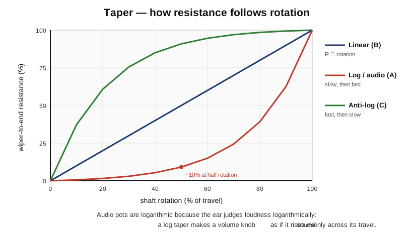
A pot’s taper describes how its resistance divides as a function of shaft position, and it is the single most misunderstood pot specification (Figure 5).
The simplest taper is linear: the wiper-to-end resistance is directly proportional to rotation, so at half rotation the wiper sits at the electrical midpoint. Linear pots suit position sensing, balance controls, and anywhere a proportional response is wanted. In the modern Asian and European coding scheme, a linear pot is marked B.
The other common taper is logarithmic, usually called audio taper and marked A. Here the resistance rises slowly at first and then steeply near the top of the travel: at half rotation the wiper may sit at only about 10% of the element. The reason is human hearing. The ear judges loudness logarithmically — a signal must roughly ten times its power to sound “twice as loud” — so a linear volume control would seem to do almost all its work in the first quarter of its travel and then barely change. A logarithmic taper compensates: it spreads the perceived change evenly across the whole rotation, so the knob “sounds” as if it rises smoothly from silence to full. Every volume control worth using is a log (audio) pot for exactly this reason. A mirror-image anti-log (or reverse-log) taper, marked C, rises fast and then slows, and is used where the log response must run the other way — some balance and expression applications, or the “cold” end of certain tone circuits.
Here a genuine trap deserves a warning. The taper letter codes are not universal. In today’s common Asian and European convention, A means logarithmic (audio) and B means linear. But some older American manufacturers used the opposite sense, with A meaning linear and other letters for the log tapers, and legacy Allen-Bradley and CTS parts followed that older scheme. A part marked “A” from a vintage American catalog and a part marked “A” from a modern distributor can behave in exactly opposite ways. The only safe practice is to read the manufacturer’s own datasheet for the taper, not to trust the letter alone — and, for a real bench check, to measure the wiper-to-end resistance at the mid-position: about half the total means linear, about a tenth means log/audio.
Real “log” pots, incidentally, are rarely a true logarithm. Manufacturing an exactly logarithmic film is expensive, so most audio pots approximate the curve with two straight-line segments — a shallow slope for the first half of travel and a steeper one after — chosen to fool the ear well enough. The approximation is close enough that no listener notices, and it keeps the part cheap.
10.3.5 Form factors and the specs that matter
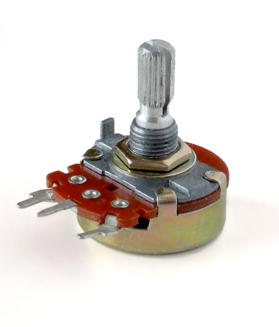
Pots come in a form for every job. The rotary single-turn panel pot of Figure 6 is the familiar knob-on-a-shaft, sweeping roughly 270° of rotation, mounted through a panel by a threaded bushing and wired through three solder lugs. The multiturn rotary pot gears the shaft down so that ten, fifteen, or twenty-five turns cover the full element, buying fine resolution and precise setting for instrumentation. The slide pot or fader replaces the arc with a straight strip and the knob with a sliding carriage — the tall linear control on a mixing console or lighting board, where an operator wants to see and set several levels at a glance. And the PCB-mount pot is a small part soldered directly to a board and adjusted by a shaft or a knurled thumbwheel, blurring into the trimmer family below.
Beyond value and taper, a handful of specifications separate a good pot from a poor one. Rotational life counts how many full sweeps the part survives before its track wears out — tens of thousands of cycles for a carbon panel pot, millions for a conductive-plastic control. Contact resistance variation (CRV) measures how much the wiper contact’s resistance jitters as it moves; high CRV is heard as scratchiness in an audio pot and seen as noise in a sensor. Residual (or end) resistance is the small resistance that remains between the wiper and an end even at the extreme of travel — it means a “volume” pot never quite reaches true silence and a divider never quite reaches zero. Taper accuracy bounds how closely the real curve follows the ideal linear or log law. And the power rating — usually a fraction of a watt to a couple of watts — limits how much a rheostat connection may dissipate, always with the caution that at a partial setting the whole current can flow through only part of the element, concentrating the heat.
10.4 Rheostats: the two-terminal muscle
A rheostat is a potentiometer’s high-power sibling — a variable resistor built and rated to carry current, wired as the two-terminal (wiper-plus-one-end) device described above. Historically the rheostat was the standard way to control power before electronics offered anything better: a wirewound resistance in series with a motor set its speed, in series with a lamp set its brightness, in series with a heater set its temperature. Theatre dimmers, model-train controllers, laboratory bench supplies, and countless motor controls were rheostats, often large enough to fill a hand, with a heavy wiper sweeping an exposed coil of resistance wire.
They are wirewound for the same reason power resistors are: only a length of resistance wire on a robust former can dissipate tens or hundreds of watts and survive the heat, and only a heavy wiper can carry the current without burning at the contact. The penalty is the stepped resolution inherent to a wound element, which for power control is irrelevant.
The rheostat’s great weakness is efficiency. Because it controls power by dissipating the excess as heat, a rheostat dimming a lamp to half brightness may waste as much power in itself as it delivers to the load — acceptable in 1920, wasteful and hot by any modern standard. This is why electronics has almost entirely displaced the power rheostat: a triac dimmer, a PWM motor controller, or a switching regulator achieves the same control by switching rather than dissipating, wasting little and running cool. Rheostats survive today in niches where their simplicity, ruggedness, or freedom from switching noise still wins — some heater and load-bank controls, calibration loads, and legacy equipment — but the family is a shadow of what it was.
10.5 Trimmers and trimpots: set and forget
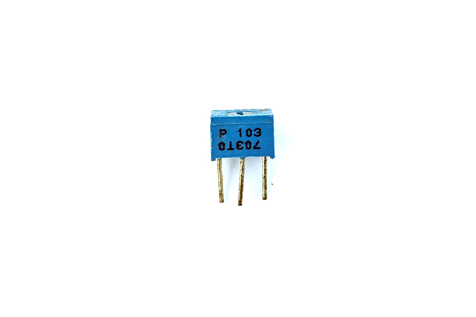
A trimmer (or trimpot, or preset) is a small potentiometer meant to be adjusted rarely — set once at the factory or during calibration, then left alone (Figure 7). It has no knob and no panel shaft; instead a screwdriver slot or a knurled wheel moves the wiper, and the part is soldered flat to a board. Trimmers exist because no manufacturing process hits every target exactly: a circuit is built to a tolerance and then a trimmer nudges one value into place — nulling an amplifier’s input offset, setting a bias current, adjusting a reference voltage, calibrating a sensor’s span. Turn it once at test and it holds.
Trimmers come in two resolutions. A single-turn trimmer sweeps its whole range in roughly three-quarters of a turn (about 240–270°), which is quick to set but coarse — a small screwdriver twitch moves the value a lot. A multiturn trimmer drives the wiper along the element with a lead screw, so that many turns of the adjustment screw cover the full range: fifteen turns for a Bourns 3006, twenty-five for the classic Bourns 3296, and similar counts across the industry. The gearing buys fine resolution and stable setting — each turn moves the value only a little, so a precise adjustment is easy and vibration is unlikely to shift it. Nearly all trimmers use a cermet element for its stability; a representative 25-turn cermet trimmer is rated around ±100 ppm/°C, half a watt at 70 °C, with values from about 10 Ω to 2 MΩ and effectively infinite resolution between its steps.
The modern trend is to replace the mechanical trimmer wherever possible. A trimpot is a moving part on a board — it can drift with vibration and thermal cycling, it needs a human with a screwdriver (or an expensive automated adjuster) at test, and it cannot be re-calibrated in the field without opening the box. The digital potentiometer and the calibration DAC, described next, do the same job with a value set in a register: adjustable under software control, immune to vibration, re-trimmable remotely, and free of the labor of a manual calibration pass. For high-volume products the digital part increasingly wins; the mechanical trimmer survives where cost, simplicity, or the need for a truly passive, power-free setting keeps it in place.
10.6 The digital potentiometer
10.6.1 A pot with no moving parts
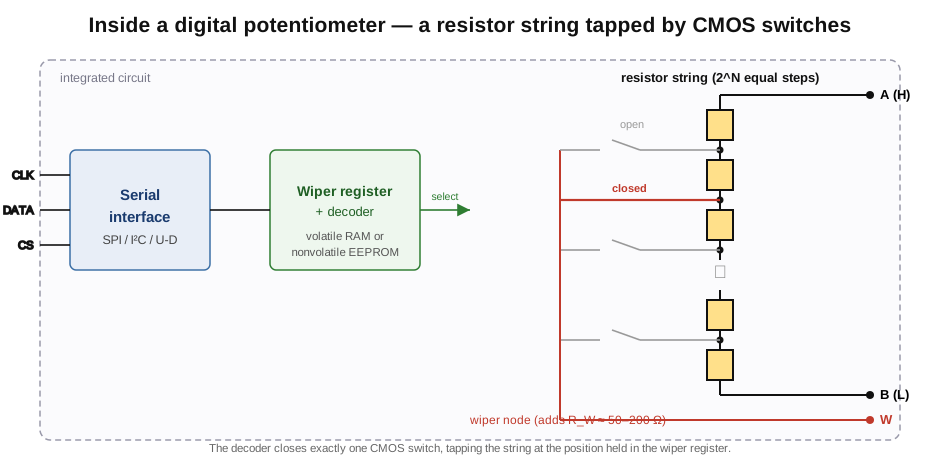
A digital potentiometer (“digipot”) is not a mechanical part at all but an integrated circuit that behaves like a three-terminal pot whose wiper is positioned by a number rather than a shaft (Figure 8). Inside, a string of many equal resistors runs between two terminals (call them H and L, the analog of the two ends), and at every junction of the string sits a CMOS analog switch. A digital block — a decoder driven by a wiper register — closes exactly one of those switches at a time, connecting that junction to the wiper terminal (W). Setting the register to a new number opens the old switch and closes another, moving the tap up or down the string. The result is a three-terminal device that can be a divider (use all three terminals) or a rheostat (use W and one end), exactly like a mechanical pot, but with the wiper set by software.
The register is loaded over a serial bus. Common interfaces are SPI and I²C for absolute positioning (write the tap number directly), and a simpler up/down (increment/decrement) interface driven by two pins for front-panel volume knobs. Resolution is the number of taps, quoted in bits or positions: 32, 64, 128, 256, or 1024 taps are typical (5 to 10 bits), so a 256-tap part divides its range into 255 equal steps. Whether the setting survives a power cycle depends on the memory: a volatile digipot keeps its wiper position in RAM and forgets it at power-down (returning to a default or mid-scale on reset), while a nonvolatile part stores the last position in on-chip EEPROM and powers up where it left off — the right choice for a set-once calibration that must persist.
10.6.2 Where it wins, and where it loses
The digipot’s strengths follow directly from being an IC. It is programmable — a processor sets and changes it on the fly, so a gain, a bias, or a reference can be adjusted in software, swept, or self-calibrated. It has no mechanical wiper to wear, corrode, or shift with vibration, so it holds its setting in environments that would ruin a trimpot. It can be adjusted remotely and re-calibrated in the field. And several can be packed into one small IC for multichannel control. These are the reasons it steadily replaces the mechanical trimmer.
Its weaknesses are just as real, and they all trace to the switch-and-string construction. The wiper connects through a CMOS switch, which has a wiper resistance of roughly 50 to 200 ohms in series with the tap — small against a 100 kΩ divider, but a serious error against a 1 kΩ one, and worse at low tap numbers where the switch resistance is a large fraction of the resistance in circuit. The part handles only modest voltage and power: the signal must stay within the supply rails (a few volts, or a limited bipolar range on specialized parts) and the string dissipates very little, so a digipot can never do a power rheostat’s job. Its resolution is discrete — it steps rather than sweeps — and each step transition can produce a small glitch as one switch opens before the next fully closes, which matters in a low-noise signal path. And the accuracy of the steps is bounded by the IC’s integral and differential nonlinearity (INL and DNL), just as in a DAC.
One subtlety turns a weakness into a strength. The absolute end-to-end resistance of a digipot is loose and drifts noticeably — its rheostat-mode temperature coefficient can be tens to hundreds of ppm/°C. But used as a divider, the output depends only on the ratio of taps along the string, and because every resistor in the string is the same film on the same die, those resistors track almost perfectly. The ratiometric temperature coefficient — the drift of the divider ratio — is therefore far smaller, often only a few ppm/°C. So a digipot used to set a voltage ratio is dramatically more stable than the same part used to set an absolute resistance, the identical ratiometric grace seen in the resistor network and the mechanical pot-as-divider. It is the recurring lesson of this whole volume: resistors on one substrate track, and the circuit that asks only for their ratio gets the benefit for free. Representative parts make the numbers concrete — a 256-position I²C digipot such as the Analog Devices AD5245 offers 5, 10, 50, and 100 kΩ end-to-end values with about a 50 Ω wiper, and Microchip’s SPI-controlled MCP41010 is a 256-tap 10 kΩ part — but the architecture is the same across the field.
10.7 Not a potentiometer: the rotary encoder
One part is so often confused with a potentiometer that it deserves a paragraph of its own. A rotary encoder looks like a panel pot — a knob on a shaft, three or more pins — but it is a switch, not a variable resistor. Turning its shaft opens and closes two internal contacts (or interrupts two optical beams) in a staggered quadrature pattern, emitting a stream of pulses whose count tells a microcontroller how far the shaft turned and whose phase tells it which way. An encoder has no resistive element and no absolute position: it reports change, not a value, it usually spins endlessly without stops, and many click through detents. It is the right part for a “digital” volume knob feeding a microcontroller or a menu selector, and the wrong mental model for anyone expecting a wiper voltage. If a knob’s datasheet talks about pulses per revolution and quadrature outputs rather than resistance and taper, it is an encoder, and it must be read by counting edges, not by measuring a divider.
10.8 What these parts do for the circuits ahead
The networks and variable resistors of this volume are the components behind a large share of the applications the selection-and-use volume will lay out. The divider that sets a reference or scales a signal, the gain-setting pair that fixes an amplifier’s gain, and the bridge that senses a small change all lean on matched resistances, and a network delivers the ratio tolerance and TCR tracking they need in one part. The pull-up and pull-down banks that a digital board scatters by the dozen collapse into bussed SIP and chip arrays. The volume, tone, balance, and bias controls of audio and instrumentation are potentiometers, their feel set by the taper and their quietness by the element. Calibration — offset null, reference trim, span adjustment — is the trimmer’s and increasingly the digital pot’s domain. And the R-2R ladder is the resistor structure that makes data conversion possible at all. In every case the underlying idea is the one this volume opened with: a resistor is most powerful not as an isolated number but in relation to another resistance — matched to it on one substrate, or split from it by a moving wiper — and the network, the pot, the trimmer, and the digipot are simply the four ways the industry sells that relationship. The next volume turns from these multi-element and variable parts to the specialty and sensing resistors — the current-sense shunt, the high-voltage and high-power constructions, and the thermistor, varistor, and photoresistor cousins that respond to the world rather than merely resisting it.
Comments (0)