Resistors · Volume 13
Measuring and Testing Resistors
13.1 Why measuring a resistor is harder than it looks
A resistor is the simplest component in electronics, and measuring one ought to be the simplest measurement: clip on two leads, read the number, done. For a 4.7 kΩ carbon film checked to see whether it is roughly the right value, that is exactly true, and any five-dollar multimeter will answer the question. But the moment the value drifts toward the extremes — a current-sense shunt of a few milliohms, an insulation resistance of hundreds of gigaohms — or the moment the question changes from “roughly what value” to “what value to a few parts per million,” the naive two-lead measurement quietly falls apart. The reading includes things the reader did not intend to measure: the resistance of the test leads, the resistance of the contacts, small thermal voltages generated where dissimilar metals meet, the self-heating of the resistor under test, and, if the part is still soldered into a circuit, every other path the current can find around it.
This volume is about closing that gap: how a resistor is actually measured, from the bench digital multimeter up through the null bridges of the metrology laboratory and the guarded high-resistance techniques that reach into the teraohms. It is where the non-idealities laid out in the volume on the real resistor — tolerance, temperature coefficient, voltage coefficient, noise, and parasitics — stop being catalog numbers and become things a person can see on an instrument. And it is where the precision types — bulk metal foil, precision wirewound, the four-terminal shunt — earn their keep, because a part that is stable to a part per million is only as good as the technique used to read it. The recurring lesson is that a good measurement is mostly about excluding what one did not mean to include, and that the right method depends almost entirely on where the resistance falls on the scale from microohms to teraohms.
13.2 The DMM ohmmeter: how it actually works
The resistance function of a digital multimeter (DMM) does not “measure resistance” directly — there is no such thing as an ohm-sensing element. Instead it exploits Ohm’s law in reverse. The instrument contains a regulated current source that pushes a known, fixed current through the unknown resistor, and a voltmeter that reads the voltage the current develops across it. The processor then divides: resistance equals voltage over current. If the source delivers exactly one milliampere and the voltmeter reads 4.700 volts, the resistor is 4.700 kΩ. That is the whole principle, and every handheld and bench ohmmeter is a variation on it.
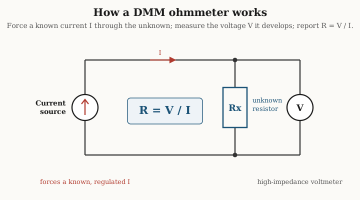
Because a fixed current through a large resistance would develop an impractically large voltage, the instrument ranges: it switches the test current down as the range goes up. A typical autoranging meter might force a milliampere on its low-ohms range, tens of microamperes in the kilohm decades, and only nanoamperes on the megohm ranges, keeping the developed voltage within the few-hundred-millivolt window its voltmeter is built for. Two consequences follow directly from this. First, the meter’s open-circuit test voltage is deliberately kept low — often under a few hundred millivolts on the ordinary ranges — so that it will not forward-bias the silicon junctions of a transistor or diode elsewhere in the circuit and so that it does not itself stress the part; this is why a DMM’s diode-test and continuity functions are separate modes with different voltages. Second, on the very high ranges the test current is so tiny that the signal is small and easily corrupted, which sets the practical ceiling of an ordinary DMM at somewhere around ten to a hundred megohms before its own leakage, input impedance, and noise begin to swamp the reading.
Some bench instruments use a subtly different scheme, a ratiometric measurement, in which the same current is passed through both the unknown and an internal precision reference resistor and the two voltages are compared as a ratio. The virtue is that the absolute accuracy of the current source cancels out — only the reference resistor’s accuracy and the voltmeter’s linearity matter — which is one reason a good 6½-digit bench DMM outperforms a handheld by so much more than its extra digits alone would suggest.
13.2.1 What the two-lead reading really includes
The trouble with the simple picture is the word “across.” The voltmeter does not read the voltage across the resistor; it reads the voltage across its own terminals, and between those terminals and the resistor’s body lie the test leads and the two contact points. Each test lead has resistance — a meter’s own leads are commonly 0.1 to 0.3 Ω the pair, and a long or thin lead far more — and every clip-to-lead junction adds a contact resistance that can range from a few milliohms on a clean, firm connection to an ohm or more on a corroded or lightly touched one. In an ordinary two-wire measurement all of this adds in series with the part, so the meter reports the resistor plus twice the lead resistance plus both contacts.
For a 4.7 kΩ resistor an extra half-ohm is one part in ten thousand and utterly invisible. For a 1 Ω resistor it is a 50% error. For a 10 mΩ shunt the leads and contacts are a hundred times larger than the thing being measured, and the two-wire reading is meaningless. This is the single most important limit of the DMM ohmmeter, and it is why any measurement below roughly a hundred ohms — and any precision measurement at all — must abandon the two-wire method for the four-wire method described next.
Two further errors of the two-lead reading deserve naming. Thermal EMFs — small voltages, typically a few microvolts up to tens of microvolts, generated wherever two dissimilar metals meet at slightly different temperatures, a Seebeck effect at the clips, the solder joints, and the internal switches — add directly to the measured voltage and matter whenever the developed signal is itself only millivolts, as on the low-ohms ranges. And loading, the mirror problem, appears at the top of the scale: measuring a 100 MΩ resistor with a meter whose own input and leakage paths are comparable to the part means the meter and the resistor form an unintended divider, and the reading sags low.
13.2.2 Measure it out of circuit
A resistor soldered onto a populated board is almost never alone. Anything wired in parallel with it — another resistor, the input resistance of an op-amp, the two directions of a semiconductor junction that the ohmmeter’s own test voltage may partially turn on, the slow charge and discharge of a nearby capacitor — becomes part of what the meter sees, and the in-circuit reading is the parallel combination of the target and every one of those paths. The reading is therefore always equal to or lower than the true value, sometimes wildly so, and it may drift as capacitors charge. The only reliable cure is to lift one end of the resistor from the board, or remove it entirely, so that the measurement sees the part and nothing else. The habit of measuring out of circuit — and of treating any in-circuit resistance reading as a rough sanity check rather than a value — separates a repeatable bench result from a misleading one.
13.3 Two-wire versus four-wire: the Kelvin measurement
The fix for lead and contact resistance is one of the most elegant ideas in instrumentation, and it is the same four-terminal idea met in the volume on specialty resistors, where the current-sense shunt carries separate current and voltage terminals so that its value is defined independently of how it is bolted into the circuit. Applied to measurement it is called the four-wire, or Kelvin, method, after William Thomson, Lord Kelvin, who formalized it in the mid-nineteenth century.
The scheme splits the two jobs a single pair of leads was trying to do. One pair of leads, the force (or current, or “source”) leads, carries the test current to the resistor. A second, entirely separate pair, the sense (or voltage) leads, connects the voltmeter directly to the resistor’s own terminals. The trick lies in what the voltmeter does not do: because a good voltmeter has an enormous input impedance — tens of megohms in a handheld, gigaohms in a bench instrument — essentially no current flows down the sense leads. And a lead that carries no current, by Ohm’s law, drops no voltage across its own resistance, no matter how large that resistance is. The sense leads therefore deliver the voltage that exists at the resistor’s body straight to the voltmeter, with the lead and contact resistance of the sense path dropping out entirely. Meanwhile the resistance of the force leads is irrelevant too: it affects how much voltage the source must produce to push the current through, but not the current itself, which is regulated, and not the voltage the sense leads report.
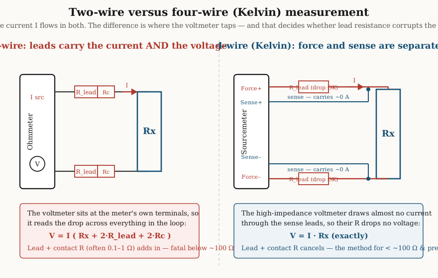
The result is that the four-wire measurement returns the voltage across the resistor and only the resistor, so that dividing by the known current gives the true value with the leads and contacts excluded. This is the definitive method for anything below about a hundred ohms and for any measurement where a part per thousand or better is wanted. It is exactly why a precision four-terminal shunt is specified and calibrated as a four-terminal object: its resistance is the ratio of the voltage at its potential terminals to the current at its current terminals, a quantity that no amount of contact resistance at the bolts can change.
13.3.1 Making a four-wire measurement on the bench
Two things are needed to do this in practice: an instrument with a four-wire resistance function and a way to make four independent connections to the part. A good bench DMM offers a “4W” or “4-wire ohms” mode that activates a second pair of input terminals (usually labeled Sense) alongside the usual pair (labeled Source or Input); the meter then forces current through the Source pair and reads voltage through the Sense pair. A dedicated source-measure unit (SMU) or sourcemeter, such as the instruments used for characterizing precision resistors and semiconductors, does the same thing with tightly controlled current and a very high-impedance voltmeter, and is the tool of choice for low-value and low-power work.
The connection to the part is made with Kelvin clips — spring clips whose two jaws are electrically isolated from each other, so that one jaw carries the force lead and the other the sense lead, and the split happens right at the resistor’s own lead. Clip a pair onto each end of the resistor and the four wires are made with the force/sense junction as close to the body as the clip can reach, which is the whole point: the closer the sense connection sits to the resistor’s material, the less of the connecting metal is included in the reading. For the lowest values the sense connections are made to dedicated potential terminals designed into the part, as on a bolt-down shunt. The discipline is always the same — put the voltage-sensing point inside the current-carrying point — and it is the single most valuable measurement habit for anyone working below a few ohms.
13.4 The Wheatstone bridge: nulling beats measuring
Every method so far has been an absolute measurement: force a current, read a voltage, trust the calibration of both, and compute. The accuracy is therefore no better than the accuracy of the current source and the voltmeter together. For most of the nineteenth and much of the twentieth century there was a fundamentally better way, and for the highest precision it is still the way: instead of measuring a voltage against a scale, balance the unknown against known resistors until a detector reads zero, and read the answer from a ratio of those knowns. This is the Wheatstone bridge, popularized by Charles Wheatstone in 1843 and covered in its historical setting in the volume on the history of the resistor.
The bridge has four resistors — four “arms” — arranged in a diamond, with a source of excitation across one diagonal and a sensitive detector across the other. Three of the arms are known: two form a fixed ratio and the third is an adjustable standard. The fourth arm is the unknown. The excitation drives current down both sides of the diamond, and each side acts as a voltage divider; the detector across the middle sees the difference between the two divider outputs. When the two dividers produce exactly the same voltage the detector reads zero — the bridge is balanced — and at that instant the four resistances are locked in a simple proportion.
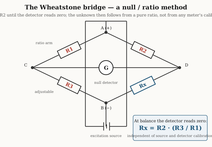
At balance the unknown is given by the balance condition — with the arms labeled as in the figure, Rx = R2·(R3/R1) — and the profound thing about this expression is what is absent from it. There is no term for the excitation voltage: a stronger or weaker, steadier or noisier source moves the null-point not at all, only how sharply the detector swings around it. There is no term for the detector’s calibration: the detector only ever has to answer the yes-or-no question “is this zero,” which even a crude galvanometer can do faithfully, and errors in its scale never enter the result. The accuracy of the measurement is inherited entirely from the accuracy of the three known arms and the precision of the ratio, and resistance ratios can be built and held far more accurately than any absolute voltage or current can be generated. That is why a null method beats an absolute one, and why the bridge dominated precision resistance metrology for a century and a half.
13.4.1 Sensitivity, and the slide-wire and decade forms
A null instrument is only as good as its ability to tell that it is not quite nulled, so sensitivity near balance matters. It is set by how much the detector deflects for a small fractional imbalance in the arms, which improves with a more sensitive detector, a higher (but self-heating-limited) excitation, and arm values chosen so the bridge is not wildly unbalanced in impedance. In practice the operator watches the detector swing one way, adjusts, watches it swing back, and closes in on the point where a small change in the standard arm produces no visible deflection.
Two classic embodiments made the adjustment practical. The slide-wire bridge replaces one ratio arm with a uniform resistance wire stretched along a meter scale, a sliding contact dividing it into two lengths whose ratio is simply the ratio of the two lengths read off the ruler — the teaching-laboratory “metre bridge.” The decade or dial bridge, such as the classic Post Office box, replaces the adjustable standard with banks of switched precision resistors in decades of ohms, tens, hundreds, and so on, so the operator dials in a four- or five-figure standard value directly. Both reduce the measurement to reading a ratio or a dial once the detector has been nulled.
13.5 The Kelvin double bridge: reaching very low resistance
The Wheatstone bridge inherits the two-wire problem at its unknown arm: the resistance of the leads and connections to the unknown add into that arm, so an ordinary Wheatstone bridge is no better than a two-wire measurement below an ohm or so. Kelvin’s answer was to graft the four-terminal idea onto the bridge itself, producing the Kelvin double bridge, the standard method for resistances from roughly a milliohm down into the microohms.
The double bridge places the unknown low resistance and a known low standard resistance in series, carrying a large common current supplied by a battery through their outer current terminals, and joined between their adjacent current terminals by a heavy conductor called the yoke or link. It is precisely this link — a short, thick, but not zero-resistance piece of copper carrying the full current — that a naive circuit could not distinguish from the unknown, and its whole design purpose is to make that link’s resistance disappear from the answer. The bridge does so with not one ratio pair but two: a first pair connected to the outer potential terminals and a second pair connected to the inner potential terminals, with the detector bridging the junction of the first pair and the junction of the second.
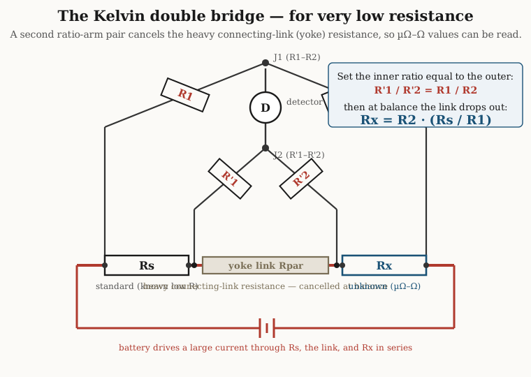
The algebra of the double bridge produces a main balance term identical in form to the ordinary bridge plus a correction term that contains the yoke resistance. The elegant result is that if the operator arranges the inner ratio to equal the outer ratio — that is, sets R’1/R’2 equal to R1/R2 — the correction term vanishes identically, and the balance collapses to Rx = R2·(Rs/R1), free of any contribution from the yoke or the connections. The measurement of a hundred-microohm shunt then becomes a comparison against a known low-value standard, with the connecting metal that would ruin a two-wire reading rendered harmless by construction. The double bridge is the natural companion to the four-terminal shunt of the specialty-resistors volume: both solve the same problem, one as a measuring instrument and one as a component, by the same Kelvin insight of separating the current path from the voltage-sensing path.
13.6 Very high resistance: megohmmeters, electrometers, and guarding
At the opposite extreme the problem inverts. When the resistance to be measured is a gigaohm or a teraohm — the insulation of a cable, the leakage across a printed-circuit board, the body resistance of a high-voltage divider — the difficulty is no longer that stray series resistance adds in, but that stray parallel leakage paths and vanishingly small currents make the true value hard to see at all. Two instruments and one technique dominate this regime.
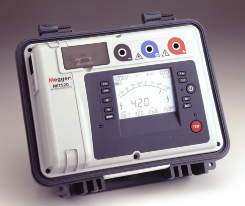
The megohmmeter, or insulation-resistance tester (the trade name Megger is the original), applies a high, standardized voltage — commonly 100, 250, 500, or 1000 V, sometimes up to 5 or 15 kV — across the insulation and measures the resulting small current, reporting the ratio as an insulation resistance from megohms to teraohms. The high voltage is not incidental: insulation resistance is neither linear nor constant, so it must be quoted at a defined test voltage, and the elevated voltage develops a measurable current where a few volts would develop essentially none. Insulation resistance matters because it is the quantity that says whether a winding, a cable, or a barrier will hold off its working voltage without leaking, tracking, or breaking down; a motor winding whose insulation has fallen from gigaohms to megohms is on its way to failure even though it still runs.
For the most extreme resistances and the smallest currents the instrument is an electrometer, a voltmeter and current meter of extraordinarily high input impedance and femtoampere-level current sensitivity, which can measure resistances into the hundreds of teraohms by forcing a modest voltage and reading a current of picoamperes or less. At these levels the measurement is defeated not by the resistor but by everything around it: the surface of the insulator, damp or dirty, offers a surface-leakage path in parallel with the true bulk resistance, and that leakage current — flowing across the surface of the very insulator whose bulk one is trying to measure — adds to the wanted current and makes the resistance read far too low.
13.6.1 Guarding and the triaxial connection
The technique that rescues the high-resistance measurement is guarding. A third electrode, a guard, is placed between the high-voltage terminal and the measuring terminal — physically a ring around the sensing electrode, or the sheath of a cable — and driven by the instrument to very nearly the same potential as the measuring terminal. Because the guard sits at almost the same voltage as the sense point, there is almost no voltage difference to drive leakage current from the guard into the measuring terminal; and because it lies between the source and the sense point, the surface-leakage current from the high side flows into the guard and returns to the source, never passing through the meter. The instrument is then left reading only the true bulk current through the insulation, and the surface path is intercepted before it can corrupt the result.
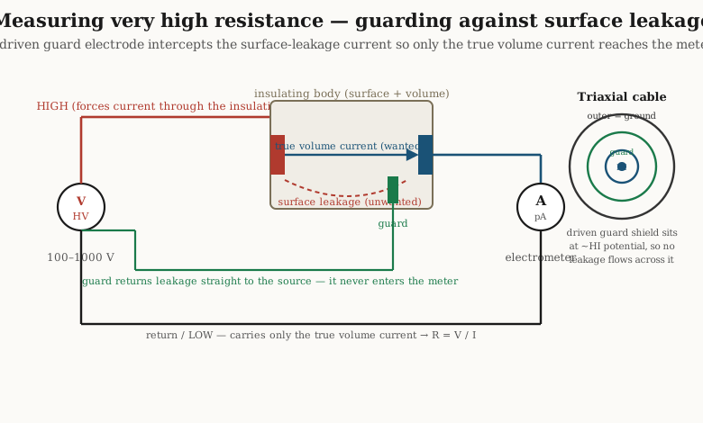
Guarding is only as good as its wiring, which is why high-resistance work uses triaxial cable rather than ordinary coaxial. Triaxial cable has three concentric conductors: a center conductor carrying the signal, an inner shield driven as the guard at the signal’s own potential, and an outer shield at ground. With no voltage across the insulation between center and inner shield, that insulation cannot leak — the cable’s own finite resistance is guarded out just as the fixture’s surface leakage is — and the measurement can reach resistances that the leakage of an ordinary coaxial cable would have made impossible. The same guard principle appears inside every electrometer and every well-designed high-megohm test fixture.
13.7 Measuring the specifications, not just the value
Reading a resistor’s ohms is only the first of its numbers. The specifications introduced in the volume on the real resistor — temperature coefficient, excess noise, self-heating, and thermal EMF — are themselves measurable, and each has a standard technique.
The temperature coefficient of resistance (TCR) is found by the two-temperature method: the resistor is measured at one stable temperature, then brought to a second — in a temperature chamber, an oven, or a stirred oil or fluid bath — allowed to settle fully, and measured again. The coefficient in parts per million per degree Celsius is the fractional change in resistance divided by the temperature change:
TCR = (R₂ − R₁) / (R₁ · (T₂ − T₁)) × 10⁶ ppm/°C.
The measurement is deceptively demanding. The two resistance readings must themselves be good to a fraction of the change being measured — a 5 ppm/°C part over a 50 °C span moves only 250 ppm, so seeing it to 10% requires reading resistance to about 25 ppm — which forces four-wire technique and a low-thermal-EMF, well-settled bench. The bath or chamber temperature must be known accurately and the part must reach true thermal equilibrium, not merely a plausible reading; and because most resistors have a curved rather than straight R-versus-temperature characteristic, a two-point TCR is only a chord across the curve, and a full characterization uses several temperatures spanning the range of interest.
Excess noise, the current-dependent flicker noise that rides on top of the unavoidable Johnson thermal noise and distinguishes a cheap carbon composition part from a quiet metal-film one, is quantified by the noise index. A standardized measurement — historically the Quan-Tech instruments and the methods codified in the relevant military and industry standards — applies a DC voltage across the resistor and measures the resulting excess noise voltage in one decade of frequency, expressing the result as a noise index in decibels relative to one microvolt of noise per volt of applied DC. A noise index of 0 dB means one microvolt of noise per applied volt per frequency decade; a good metal-film part might be −20 or −30 dB, while a carbon composition part can sit near 0 dB or worse. Because the excess noise is proportional to the applied voltage, it is only visible under a DC bias and vanishes on an unpowered part, which is why it must be measured with the resistor carrying current.
Self-heating is not a resistor property so much as a measurement pitfall, and it is measured by looking for its absence. Any test current heats the part by its own I²R dissipation, and if the part has a nonzero TCR its value shifts as it warms, so a reading taken the instant the current is applied differs from one taken a minute later. The test for it is simple: measure at one power level, then at a distinctly lower one, and see whether the value changes. If it does, the measurement is self-heating-limited and the honest value is the one approached at low power — which is exactly why precision resistance measurement uses the smallest current that still gives an adequate signal, and why the definition of a standard resistor’s value specifies the power at which it is to be used.
Thermal EMF, the parasitic Seebeck voltages that plague every low-level DC measurement, is cancelled by the oldest trick in the book: current reversal. The measurement is made once with the test current flowing one way and once with it reversed, and the two results are averaged. The genuine I·R drop reverses sign with the current, but the thermal offset voltage does not — it depends only on temperature, not on current direction — so averaging the magnitudes of the two readings cancels the offset while preserving the resistance. Good bench meters do this automatically under names such as “offset compensation,” pulsing the current on and off or reversing it and subtracting; on a manual bridge the operator reverses the battery and averages. It is the reason a careful low-ohms reading is always taken in both current directions.
13.8 Standards, traceability, and the calibration chain
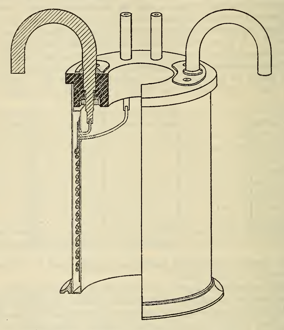
A measurement is a comparison, and every comparison eventually rests on something taken as known. For resistance that something is the standard resistor: a specially made, exceptionally stable resistor whose value is certified and whose drift and temperature behavior are characterized and tracked. The classic laboratory standard is a four-terminal Manganin element — Manganin being a copper-manganese-nickel alloy chosen for its near-zero temperature coefficient near room temperature and small thermal EMF against copper — sealed against humidity and immersed in oil so that the heat of the measuring current is carried away and the element stays at a known, constant temperature. The venerable Thomas-type 1 Ω standard and the modern sealed 10 kΩ standard such as the ESI SR104 are of this kind: they hold their temperature coefficient to better than 0.1 ppm/°C, drift by well under a part per million per year, and carry a built-in thermometer well so the exact element temperature is known when the tiny residual tempco is corrected out.
Standards exist at fixed decade values — 1 Ω, 10 Ω, 100 Ω, 1 kΩ, 10 kΩ — but working resistors come at every value, so a way is needed to transfer a known value from one decade to another without losing accuracy. The classic device is the Hamon transfer standard, a set of ten closely matched resistors that can be connected by a switch either all in series or all in parallel. Ten equal resistors in series present ten times one resistor’s value; the same ten in parallel present one tenth of it; the ratio between the two configurations is therefore exactly one hundred to one, and — this is the subtlety — that ratio is accurate to second order in how well the ten resistors are matched, so even resistors matched only to a part in a thousand yield a 100:1 ratio good to a part in a million or better. A Hamon divider thus walks a calibration up or down the decades — from a 1 Ω standard to 100 Ω, from 10 kΩ to 100 Ω — with a transfer accuracy far beyond what any single resistor’s absolute tolerance could provide.
Above the world of physical standards sits the definition itself. Since the 2019 redefinition of the SI, the ohm is fixed through the exact numerical values of the Planck constant and the elementary charge, and it is realized in practice through the quantum Hall effect: a suitable device in a strong magnetic field at cryogenic temperature exhibits Hall resistance plateaus at exact submultiples of the von Klitzing constant, R_K = h/e² ≈ 25 812.807 Ω, a value reproducible to parts in a billion and independent of the material or the individual device. National metrology institutes maintain the ohm against this quantum standard and disseminate it downward: the quantum Hall resistance calibrates the laboratory’s group of oil-bath standards, those standards calibrate the reference resistors and precision bridges of a calibration laboratory, and those in turn calibrate the bench meters and standards that a working engineer relies on. This unbroken sequence of comparisons, each with a stated uncertainty, is traceability — the property that lets a number read on a bench meter be tied, through a documented chain, all the way back to the definition of the unit.
13.9 Practical bench technique and choosing the method
Most of good resistance measurement is a handful of habits that flow directly from everything above. Let the reading settle. A resistor takes seconds to a minute to reach thermal equilibrium with its test current and its surroundings, and a meter’s own reference settles too; a value read the instant the leads touch is rarely the value read after the reading stops moving, and the difference is self-heating and thermal EMF working themselves out. Measure out of circuit, or at least lift one lead, so that parallel paths and semiconductor junctions cannot join the measurement. Keep the contacts clean and firm — oxide, oil, and a light touch all add contact resistance that a two-wire reading cannot tell from the part — and for anything below a few ohms use four-wire Kelvin connections so that the contacts do not matter at all. Reverse the current (or use the meter’s offset-compensation mode) whenever the developed voltage is only millivolts, to cancel thermal EMFs. And use the smallest test power consistent with a clean reading, so that self-heating does not shift a part with any appreciable temperature coefficient.
Above all, the right method depends on the value. There is no single best way to measure a resistor; there is only the best way to measure a resistor of a given size, because the errors that dominate at one end of the scale are invisible at the other. The table below collects the regimes.
Table 1 — Practical bench technique and choosing the method
| Resistance range | Dominant difficulty | Right method | Typical instrument |
|---|---|---|---|
| µΩ – mΩ | Lead and yoke/link resistance swamps the part | Kelvin double bridge; four-wire against a low-value standard | Double bridge; micro-ohmmeter; SMU with Kelvin leads |
| mΩ – ~100 Ω | Lead and contact resistance dominate | Four-wire (Kelvin) — force/sense split | 4-wire bench DMM or sourcemeter, Kelvin clips |
| ~100 Ω – ~1 MΩ | The easy middle; ordinary errors small | Two-wire DMM is adequate; four-wire or Wheatstone bridge for precision | Handheld or bench DMM; Wheatstone/decade bridge |
| ~1 MΩ – ~100 MΩ | Meter loading, leakage, small signal | Bench DMM high ranges; begin to guard | 6½-digit bench DMM; teraohmmeter |
| ~100 MΩ – TΩ+ | Surface leakage; picoampere currents; nonlinearity | Applied-voltage method with guarding and triaxial cabling | Megohmmeter / insulation tester; electrometer |
Read down the middle column and the through-line of the volume appears: below a hundred ohms the enemy is series resistance and the answer is to separate current from voltage, the Kelvin idea, in its four-wire and double-bridge forms; in the comfortable middle almost anything works, and a bridge is reached for only when parts per million are wanted; and above a megohm the enemy becomes parallel leakage and tiny currents, and the answer is high voltage, high input impedance, and guarding.
13.10 What measurement reveals
Measurement is where the abstractions of the earlier volumes become concrete. The tolerance band printed on a part is only a promise until a four-wire reading confirms it; the temperature coefficient quoted in parts per million is only a catalog line until a two-temperature run makes the resistor’s value visibly walk with the bath; the excess-noise index is only a letter code until a biased measurement in a quiet fixture shows the carbon part hissing where the metal-film part is silent. The non-idealities of the real resistor — the lead resistance the datasheet never mentions, the thermal EMFs at the clips, the surface leakage across a dirty board, the self-heat that shifts the reading — are exactly the things a careful measurement is built to exclude, and learning to measure a resistor well is largely learning to see and defeat them one by one.
It is also where the precision types earn their price. A bulk-metal-foil or precision-wirewound resistor stable to a part per million is wasted behind a two-wire measurement whose leads and contacts cost a hundred times that, and it shines only when read with four-wire technique against a traceable standard on a settled bench. The instruments of this volume — the four-wire bench meter, the Wheatstone and Kelvin bridges, the guarded electrometer, the oil-bath standard, and the quantum Hall realization behind them all — are the apparatus that turns a stable resistor into a known one. The reference volume that follows gathers the tables, codes, and constants that the whole dive has leaned on into one place to be kept beside the bench.
Comments (0)