Transformers and Transformer Winding · Volume 1
What a Transformer Is: Mutual Inductance and the Turns Ratio
1.1 The One-Sentence Answer, and Then the Everyday One
A transformer is a device that moves electrical energy from one circuit to another through a shared magnetic field, and in the crossing it can trade voltage for current — stepping the voltage up or down by whatever ratio the builder wound into it. That is the sentence to carry away if only one survives. Everything in this volume, and much of the thirteen that follow, is an unpacking of it: what “moves energy through a magnetic field” actually means, why the two circuits never touch, why the trade between voltage and current is exact, and why a component with no moving parts and no wire joining its two halves nonetheless sits at the heart of every power grid, every tube amplifier, and every phone charger ever built.
The everyday physical reality is simpler than the sentence. Take two coils of insulated wire and wind them close together on the same lump of iron — a laminated stack, a ring, a shaped block — so that they share the same magnetic path. Feed an alternating current into the first coil, called the primary, and it throws a rising-and-falling magnetic field into the iron. That changing field sweeps through the second coil, the secondary, and induces a voltage in it. No electrical wire runs from the primary to the secondary; the only thing that crosses the gap is the magnetic field in the iron. And here is the trade that makes the component earn its name: the voltage that appears on the secondary is set by the ratio of the turns. Wind ten times as many turns on the primary as on the secondary, and the secondary delivers one-tenth the voltage — but, because energy is conserved, it can deliver ten times the current. The transformer transforms: it takes power in at one voltage-and-current pairing and hands it back out at another, without a direct connection and, ideally, without loss.
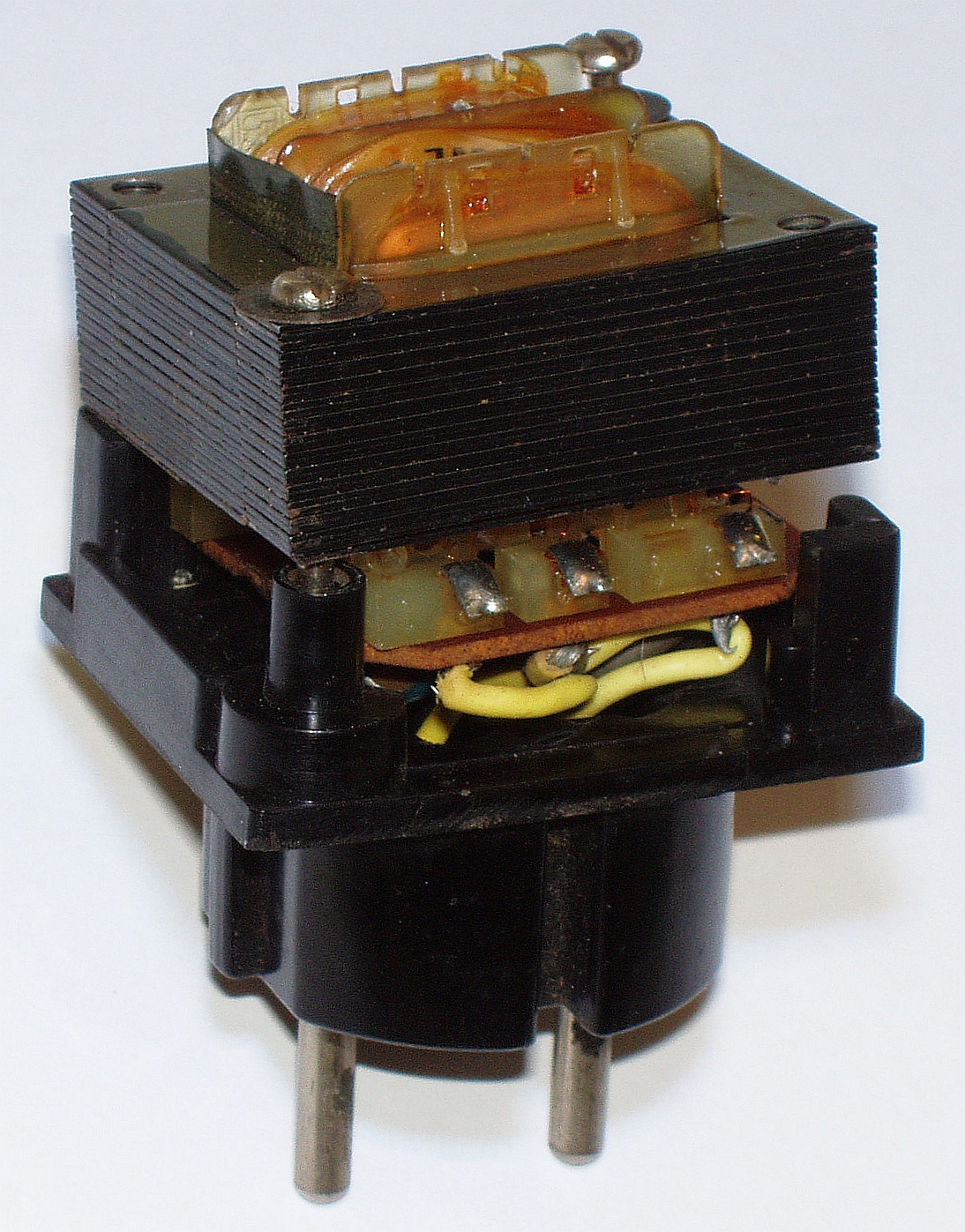
The photograph shows the humblest and most common member of the family: a small mains transformer of the kind found by the million inside older power supplies. The black stack of interleaved plates is the core, made of many thin steel laminations rather than a solid block — for reasons a later volume makes much of. Wrapped around the middle limb of that core, hidden inside the plastic bobbin, are the two windings, the primary that connects to the wall and the secondary that feeds the low-voltage circuit. The pins at the bottom carry those windings out to a printed-circuit board. It is a plain object, but everything this deep dive covers is present in it: the two coils, the shared iron, the turns that set the ratio, and the fact that the wall side and the circuit side are electrically strangers to one another.
This is the fourth and final entry in a connected series on the passive components of electronics — capacitors, coils, resistors, and now transformers — and it leans hardest on the third-of-its-siblings that came just before it, the companion dive on coils and coil winding. A transformer, as the next section makes plain, is simply two coupled coils, so nearly everything established there about the magnetic field, about inductance and the henry, about Faraday’s and Lenz’s laws, carries straight over. Rather than re-derive that physics from the ground up, this volume builds on it: where the coils dive studied a single winding reacting to its own changing field, this one adds a second winding and asks what the first coil’s field does to it. A reader who has been through the coils material will find much of this comfortably familiar; a reader arriving fresh will still be able to follow, because the essential ideas are recalled as they are needed.
1.2 Two Coupled Coils: Mutual Inductance and the Second Winding
The coils dive built its whole story on a single fact discovered by Ørsted and Faraday: a changing magnetic flux through a loop of wire induces a voltage in that loop. In symbols, the induced electromotive force — the EMF, the “push” that drives current — equals the number of turns times how fast the flux is changing, EMF = −N · (dΦ/dt). The letter Φ (phi) stands for the magnetic flux, the total amount of magnetic field threading through the coil, measured in webers; dΦ/dt is calculus shorthand for how fast that flux is changing, in webers per second, and one weber per second is by definition one volt. The minus sign is Lenz’s law, the rule that the induced voltage always opposes the change that produced it. When a coil’s own current changes and it induces a voltage in itself, that is self-inductance, measured in henries, the property that gave the coils dive its name.
A transformer takes exactly this machinery and adds a second coil in the path of the first coil’s flux. Now the changing flux made by current in the primary threads not only through the primary itself but also through the secondary sitting beside it on the same core. By Faraday’s law, that changing flux induces a voltage in the secondary just as surely as it induces the back-EMF in the primary. The new quantity that measures how effectively one coil’s changing current induces a voltage in the other is called the mutual inductance, symbol M, and it is measured in henries just like ordinary self-inductance. Where self-inductance L answered the question “how much voltage does a coil induce in itself when its own current changes,” mutual inductance M answers “how much voltage does coil one induce in coil two when coil one’s current changes.” The defining relation is the natural companion to the self-inductance formula: the voltage appearing across the secondary equals the mutual inductance times the rate of change of the primary current, v₂ = M · (di₁/dt). Two coils that share flux this way are said to be magnetically coupled, and M is the measure of the coupling.
How much of the primary’s flux actually reaches the secondary is captured by a number between zero and one called the coupling coefficient, symbol k. If every field line made by the primary passes through the secondary, the coupling is perfect and k equals one; if the two coils are far apart or poorly aligned so that only a fraction of the flux is shared, k is small. The mutual inductance ties to the two self-inductances through k by the relation M = k · √(L₁ · L₂). A power transformer wound tightly on a closed iron core, where the iron shepherds almost all of the flux around a shared loop, achieves a k very close to one — coupling of 0.99 and better — and that near-perfect coupling is exactly what makes it behave like the clean, ideal transformer this volume is about. Loosely coupled coils, with k well below one, behave quite differently and become the subject of later volumes on leakage and on RF transformers. For now, take the coupling as perfect: whatever flux the primary makes, the secondary sees.
1.2.1 Primary, Secondary, and the Core’s Job
With two windings in the picture, the vocabulary firms up. The primary is the winding fed from the source — the coil that is driven, that takes energy in. The secondary is the winding connected to the load — the coil that is induced, that gives energy out. The labels are about role, not construction; a transformer run backwards simply swaps which winding is called which. Between them sits the core, and the core has one job: to gather the magnetic flux and guide it from the primary through the secondary with as little of it straying off into the surrounding air as possible. Wind the two coils on nothing but air and only a small fraction of the primary’s flux will find the secondary; the coupling k is poor and the transfer weak. Thread them both onto a closed loop of iron and the iron, which carries magnetic flux hundreds or thousands of times more readily than air, becomes a kind of magnetic pipe that conducts nearly all the flux around from one winding to the other. The core concentrates the field and shares it. That is why the classic transformer is built the way the photograph shows: a closed ring or frame of iron with both windings clasped around it.
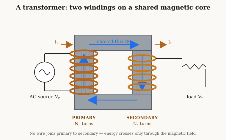
The figure strips the object down to the idea. On the left limb of the core, the primary of Np turns is driven by an alternating source at voltage Vp, drawing a primary current Ip. That current makes a flux Φ that circulates around the closed core — the blue loop — and because the core is a closed magnetic path, essentially all of that flux also passes down the right limb, through the secondary of Ns turns, where it induces the secondary voltage Vs and, with a load connected, drives the secondary current Is. The heavy point the diagram is drawn to make is the one already stated twice, because it is the point people find hardest to believe on first meeting: there is no electrical connection between the two windings. The energy that leaves the source on the left and arrives at the load on the right makes the trip entirely as a magnetic field in the iron. That is not a detail; it is the whole reason a transformer can also serve as an isolator, a theme returned to below.
1.3 The Turns Ratio: Volts Up, Volts Down
Now to the trade that gives the transformer its power, and its name. Because the same changing flux Φ threads through every turn of both windings, and because Faraday’s law says each turn contributes an equal share of induced voltage, the voltage across a winding is simply proportional to how many turns it has. The primary, with Np turns, develops a voltage of Np times the per-turn voltage; the secondary, with Ns turns, develops Ns times that same per-turn voltage. Divide one by the other and the per-turn voltage cancels, leaving the single most useful relation in the subject:
Vs / Vp = Ns / Np
The ratio of secondary voltage to primary voltage equals the ratio of secondary turns to primary turns. This quotient is called the turns ratio, and it is the number a transformer designer chooses first and lives with ever after. It is worth pinning down a small vocabulary knot before it causes confusion. Engineers describe a transformer by its turns ratio written primary-to-secondary — a “10:1 transformer” has ten primary turns for every secondary turn, meaning Np:Ns = 10:1. Such a transformer steps down, because more primary turns than secondary turns makes Vs smaller than Vp. If it helps, call the voltage-scaling factor n = Ns/Np; then Vs = n · Vp, and for the 10:1 step-down, n = 1/10. A transformer with more secondary turns than primary turns (Ns greater than Np, n greater than one) is a step-up transformer and raises the voltage; one with fewer is a step-down and lowers it. The same physical object run in reverse does the opposite job, which is why the primary and secondary labels follow the wiring, not the winding.
So much for voltage. What about current? Here the second half of the trade appears, and it follows not from Faraday’s law but from the conservation of energy. An ideal transformer — one with no losses, the abstraction this whole volume works within — cannot create energy, so the power flowing in at the primary must equal the power flowing out at the secondary. Power is voltage times current, so Vp · Ip = Vs · Is. The secondary got more voltage (in a step-up) only by the flux linking more turns; energy was not manufactured, so the extra voltage must be paid for with less current, and vice versa. Rearranging the power balance gives the current relation, which is the turns ratio inverted:
Is / Ip = Np / Ns
Current scales inversely with turns. The winding with fewer turns carries the larger current; the winding with more turns carries the smaller current. There is a tidy way to see why this must be so, one that will reappear throughout the series: a transformer conserves ampere-turns. The magnetic drive a winding applies to the core is its number of turns times its current, N · I, and in an ideal transformer the primary’s ampere-turns and the secondary’s ampere-turns balance — Np · Ip on one side, Ns · Is on the other — so that the net magnetizing effect stays fixed. Turns times current is the same on both sides, which is precisely the current relation above rearranged. Voltage follows turns; current follows turns backwards; and the product, the power, comes out the same on both sides because the transformer is a broker, not a bank — it re-denominates energy, it does not print it.
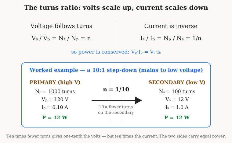
A concrete case makes the trade tangible, and it is the everyday one: turning the mains into a safe low voltage. Suppose the primary is wound with 1000 turns and connected to a 120-volt supply, and the job is to produce 12 volts. Since Vs/Vp = Ns/Np, the secondary needs Ns = Np · (Vs/Vp) = 1000 · (12/120) = 100 turns. A 10:1 turns ratio delivers the 10:1 voltage step-down. Now load that secondary so it delivers, say, one ampere to the circuit. The power on the secondary is 12 V × 1 A = 12 watts, so the ideal primary must also draw 12 watts, which at 120 volts is only 0.1 ampere. The low-voltage side carries ten times the current of the high-voltage side — exactly the inverse of the turns ratio. This is not a quirk of the example; it is the iron law of the device, and it has a blunt practical consequence the winding volumes dwell on: the low-voltage secondary, carrying the larger current, must be wound with thicker wire than the high-voltage primary, or it will overheat. Volts and turns go together; current and wire-gauge go together the other way.
1.4 Impedance Transformation: the N-Squared Trick, Again
There is a third thing a transformer transforms, and it is the one that most surprises the newcomer while most delighting the engineer: it transforms impedance. Impedance, symbol Z and measured in ohms, is the general opposition a circuit offers to alternating current — resistance and reactance rolled into one number, the AC generalization of plain resistance. A loudspeaker presents an impedance of a few ohms; the output of a vacuum tube wants to work into thousands of ohms; an antenna feedline is 50 ohms; the input of an amplifier stage might be tens of thousands. Matching these mismatched impedances to one another is a recurring problem in electronics, and the transformer is one of the oldest and cleanest tools for it.
Here is the effect. Connect a load of impedance Zs across the secondary. Look into the primary terminals and ask what impedance the source appears to be driving. It is not Zs. Because the transformer scales voltage by the turns ratio and current by its inverse, and impedance is voltage divided by current, the impedance seen at the primary is scaled by the turns ratio squared:
Zp = (Np / Ns)² · Zs
The load, viewed through the transformer, appears multiplied by the square of the primary-to-secondary turns ratio. This is the same N-squared relationship that governed a coil’s inductance in the companion dive, where L rose with the square of the number of turns, and it appears here for a closely related reason: turns do double duty, scaling voltage one way and current the other, and impedance — being their ratio — feels both factors at once, so the turns ratio enters twice and the effect goes as the square. Anyone who internalized “double the turns, quadruple the inductance” from the coils material already has the instinct for “double the turns ratio, quadruple the reflected impedance.”
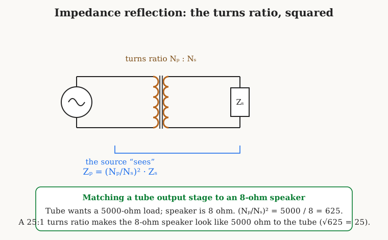
The classic application, and the one the figure works through, is the output transformer of a vacuum-tube audio amplifier. A power tube delivers its power most happily into a load of several thousand ohms — say 5000 ohms — but a loudspeaker is only 8 ohms. Connect the tube straight to the speaker and almost none of the tube’s available power reaches the cone; the mismatch throttles it. Insert a transformer whose turns ratio makes the 8-ohm speaker look like 5000 ohms to the tube, and the power flows. The ratio required follows straight from the formula: (Np/Ns)² = Zp/Zs = 5000/8 = 625, so Np/Ns = √625 = 25. A 25:1 step-down transformer presents the tube with the 5000 ohms it wants while feeding the 8-ohm speaker with the stepped-down voltage and stepped-up current it needs. Every tube guitar amp and hi-fi amplifier ever built relies on exactly this trick, and it is why the output transformer is the most sonically important — and expensive — magnetic part in such an amplifier. The same impedance-matching physics recurs in radio, where transformers and their transmission-line cousins match antennas to feedlines and stages to one another; those RF cases get their own volume later in the series. The lesson to carry forward is compact: a transformer reflects impedance by the square of its turns ratio, which turns it into a continuously adjustable impedance-matching lever.
1.5 The Ideal Transformer, and a Glance at Reality
Every relation stated so far — voltage proportional to turns, current inverse to turns, power in equal to power out, impedance scaled by turns squared — belongs to the ideal transformer, a deliberately simplified model in which the coupling is perfect (k = 1), the windings have no resistance, the core swallows no energy, and the transformer needs no current at all to magnetize itself. The ideal transformer is not a lie; it is a superb first approximation. A well-made power transformer or audio transformer follows these relations closely enough that a designer can lay out a whole circuit using them and be right to within a few percent. It is the right tool for this opening volume, and it is where a newcomer should build intuition, unclouded by second-order effects.
But a real transformer departs from the ideal in ways worth naming now so the reader knows they are coming, because the next volume is devoted entirely to them. The coupling is never quite perfect: a little of the primary’s flux escapes the core and fails to link the secondary, an effect modeled as leakage inductance, and it is what makes a real transformer’s output voltage sag under load and limits how fast it can pass a signal. The windings are copper, not superconductor, so they have resistance and dissipate heat as copper loss whenever current flows. The core itself is not free to magnetize: pushing its flux back and forth every cycle costs energy to hysteresis and to eddy currents swirling in the iron — the core loss that warms a transformer even with nothing connected to the secondary, and the reason the core is built of thin insulated laminations rather than a solid block. And the transformer draws a small magnetizing current simply to establish the flux in the core, present even at no load. These imperfections turn the crisp equalities of the ideal model into close-but-not-exact approximations, and they set the limits on efficiency, regulation, and bandwidth that a designer must respect. For this volume, set them aside; assume the ideal. The very next volume takes them up in earnest, replacing the ideal transformer with a proper equivalent circuit that accounts for every one of them.
1.6 The Dot Convention and Winding Phase
A transformer’s turns ratio tells how big the secondary voltage is, but not which way it points at any instant — whether the secondary’s top terminal swings positive at the same moment the primary’s top terminal does, or the opposite moment. This matters enormously the instant more than one winding must be combined: connect two secondaries in series expecting their voltages to add, wire one backwards, and they subtract to zero instead; build a push-pull amplifier or a full-wave rectifier with a winding’s phase reversed and it simply will not work. The relative timing of the windings is called their phase or polarity, and because it depends on the physical direction each coil was wound — clockwise or counter-clockwise around the core — it cannot be read off a plain drawing of loops. Engineers therefore mark it explicitly, with the dot convention.
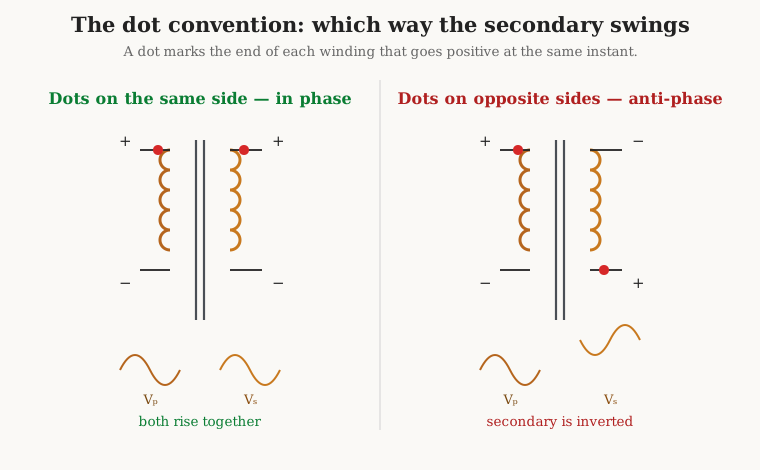
The rule is simple to state and worth memorizing exactly. A dot is placed at one end of each winding on the schematic, and the meaning is this: the dotted terminals all reach their positive peak at the same instant. When current flows into the dotted end of the primary, the induced voltage makes the dotted end of the secondary positive with respect to its other end. That is the whole convention. If the two dots are drawn on the same side of the symbol, as in the left half of the figure, the windings are in phase: the secondary voltage rises and falls in lockstep with the primary, and a signal passes through without inversion. If one dot is on the opposite end, as in the right half, the secondary is anti-phase or inverted: when the primary’s top goes positive, the secondary’s top goes negative. The dots are not decoration; they are the only thing on the schematic that records how the coils were actually wound, and a technician tracing a circuit or a builder connecting multiple windings ignores them at their peril. A later volume on measuring transformers shows how to find the phasing of an unmarked transformer on the bench — a quick test with a battery and a meter, or an oscilloscope — but the convention drawn here is how that hard-won knowledge gets recorded once it is known.
1.7 Why It Only Works on Alternating Current
Everything in this volume has quietly depended on one word: changing. Faraday’s law induces a voltage only from a changing flux, and the flux changes only because the primary current changes. This leads to the single most defining, and to newcomers most startling, property of the transformer: it works only on alternating current. Feed the primary a steady direct current and the transformer does nothing useful at all. A steady DC in the primary makes a steady flux in the core; a steady flux has dΦ/dt equal to zero; and by Faraday’s law a flux that is not changing induces exactly zero volts in the secondary. The secondary sits dead. A transformer is not a general-purpose energy conduit that happens to prefer AC — it is inherently, unavoidably an alternating-current device, blind to any signal that does not change.
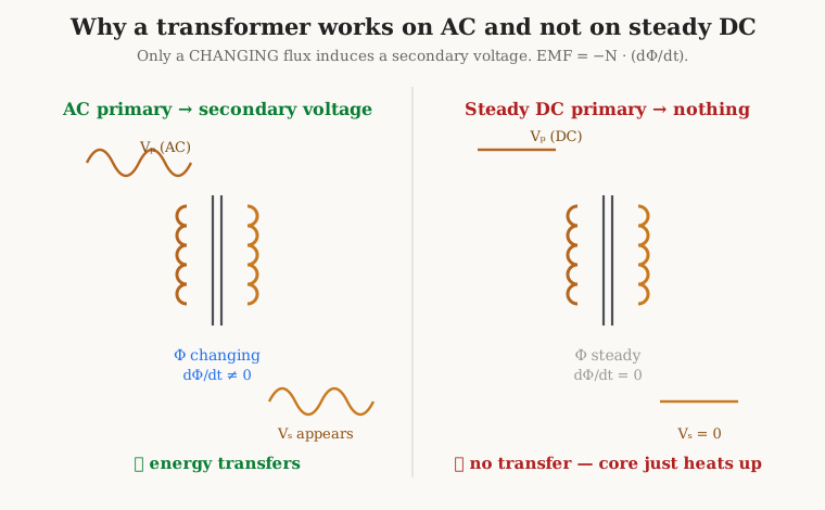
Worse than merely useless, a DC-energized primary is dangerous to the transformer. In normal AC operation the primary’s current is held in check by its inductance: the winding’s self-inductance opposes the changing current with a back-EMF, so a mains transformer draws only a small magnetizing current even across a substantial voltage. But inductance opposes only changing current; against steady DC it offers no opposition at all. Apply DC to a primary and the only thing limiting the current is the winding’s own copper resistance, which is small — often just a few ohms. A large, unchecked current pours in, drives the core deep into saturation (a state, met in the coils dive, where the iron can hold no more flux and the inductance collapses), and the winding heats until its insulation chars and it burns out. This is not a subtle failure; it is a fast and smoky one, and it is a standard way to destroy a transformer. The rule for the bench is absolute: never put steady DC across a transformer winding meant for AC.
This one requirement — that transformers demand AC — is quietly one of the most consequential facts in the history of technology, because it is a large part of why the electrical grid is alternating current. The transformer’s ability to step voltage up and down efficiently is what makes long-distance power distribution practical: generate at a moderate voltage, step up to hundreds of thousands of volts for the transmission lines (high voltage means low current for a given power, and low current means small losses in the wires), then step back down in stages for delivery to homes. Only AC can be transformed this way, so the grid was built on AC, and the transformer’s insistence on a changing field is written into the wiring of civilization. That story — the “war of currents” between the AC of Westinghouse and Tesla and the DC of Edison, the invention of the practical transformer by Gaulard and Gibbs and by the Hungarian ZBD team, Stanley’s demonstrations for Westinghouse — is the subject of the historical volume later in this series, and it turns entirely on the physics of this section.
1.8 Isolation: No Wire Between the Two Sides
Return one last time to the fact the figures kept insisting on: in a transformer there is no ohmic — no direct, metallic — connection between the primary and the secondary. The energy crosses as a magnetic field, not as a current through a shared wire. This property, almost incidental to the transformer’s main job, turns out to be so useful in its own right that whole classes of transformer are built for it alone. It is called galvanic isolation, and it means the two circuits can exchange energy or signal while remaining, as far as steady voltages and DC are concerned, complete strangers.
Isolation buys three distinct and valuable things. The first is safety. Because the secondary shares no wire with the primary, it need not share the primary’s connection to the dangerous mains and its earth reference; a properly designed isolation transformer lets a device run from the wall while its low-voltage circuitry floats free of the lethal mains potential, so that touching one point of the secondary circuit does not complete a path back through the mains and through a person. This is why medical equipment, test benches, and any gear a technician must probe while live so often run through isolation transformers, and it is why the insulation between primary and secondary in a mains transformer is treated as a life-safety matter — a theme the winding and safety volumes take very seriously, with their creepage distances, insulation classes, and hi-pot tests. The second gift is the breaking of ground loops. When two pieces of equipment are tied together through their signal cables and also through their separate mains earths, stray currents can circulate in the loop and inject hum and noise; a signal or audio isolation transformer, passing the wanted signal magnetically while blocking the DC path, snips that loop and silences the hum. The third is level shifting: because the secondary floats, its voltages can be referenced to whatever the receiving circuit needs, letting a signal hop between circuits sitting at wildly different DC potentials — the everyday job of the gate-drive and interface transformers in power electronics. All three benefits flow from the same simple fact, that the only bridge between the windings is the magnetic field.
1.9 Reading the Symbols
A transformer announces itself on a schematic as two coils drawn back to back — two of the same looped squiggle used for an inductor, placed facing each other to show that they share a magnetic path. The marks around and between those two coils tell the reader what kind of transformer it is and, often, what it is for. Learning to read them is a quick and rewarding skill.
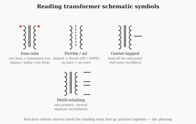
The base symbol is the pair of facing coils. What sits between them names the core. Two solid parallel bars drawn between the coils mean a solid, laminated iron core — the mark of a mains-frequency power transformer or an audio transformer, the workhorses of the low-frequency world. A broken or dashed line between the coils means a ferrite core, the near-universal choice for the high-frequency transformers in switching power supplies and radios, where a solid iron core would lose far too much energy. No line at all, just the two bare coils, means an air-core transformer, used at radio frequencies where even ferrite is too lossy and the coupling is deliberately loose. Beyond the core marking, two more features recur constantly. A center tap is an extra lead brought out from the electrical middle of a winding, splitting it into two equal halves; it is drawn as a wire off the midpoint of the coil and is the heart of the full-wave rectifier and the push-pull amplifier, both of which need a winding with a defined center. And a multi-winding transformer carries one primary but several separate secondaries stacked on the same core, each isolated from the others and each with its own turns ratio, so that a single transformer can deliver several different voltages at once — the arrangement inside most power supplies. Overlaid on any of these, the dots of the previous section record the phasing. A reader who can glance at a transformer symbol and read off “laminated core, center-tapped secondary, this end in phase with that one” is reading the designer’s intent directly, which is the entire point of a schematic.
1.10 Why Transformers Matter — and the Fourteen-Volume Road Ahead
Having built the transformer up from two coupled coils, it is worth stepping back to see what the component does, because the reach of it is genuinely enormous. The transformer is the device that makes the electric grid possible, stepping generated power up to the high voltages that cross the country with little loss and back down to the safe voltages that enter a house — the single most important reason the world’s power is alternating current. It is the power supply front end that converts the mains to whatever low voltage an electronic device needs, whether as a bulky iron transformer in a linear supply or a tiny high-frequency ferrite transformer buzzing inside a phone charger. It is the output transformer that lets a vacuum tube drive a loudspeaker and the audio and telecom transformer that matches, isolates, and balances signals. It is the isolation barrier that keeps mains voltages away from the parts a person can touch, and the instrument transformer — the current transformer and voltage transformer — that lets a small, safe meter measure a huge, dangerous current or voltage. It is the impedance-matching element in radios and the balun that feeds a balanced antenna from an unbalanced cable. And it is the flyback and forward transformer at the heart of every switch-mode power supply, the reason a modern charger can be the size of a matchbox. Very little electrical technology functions without a transformer somewhere in it.
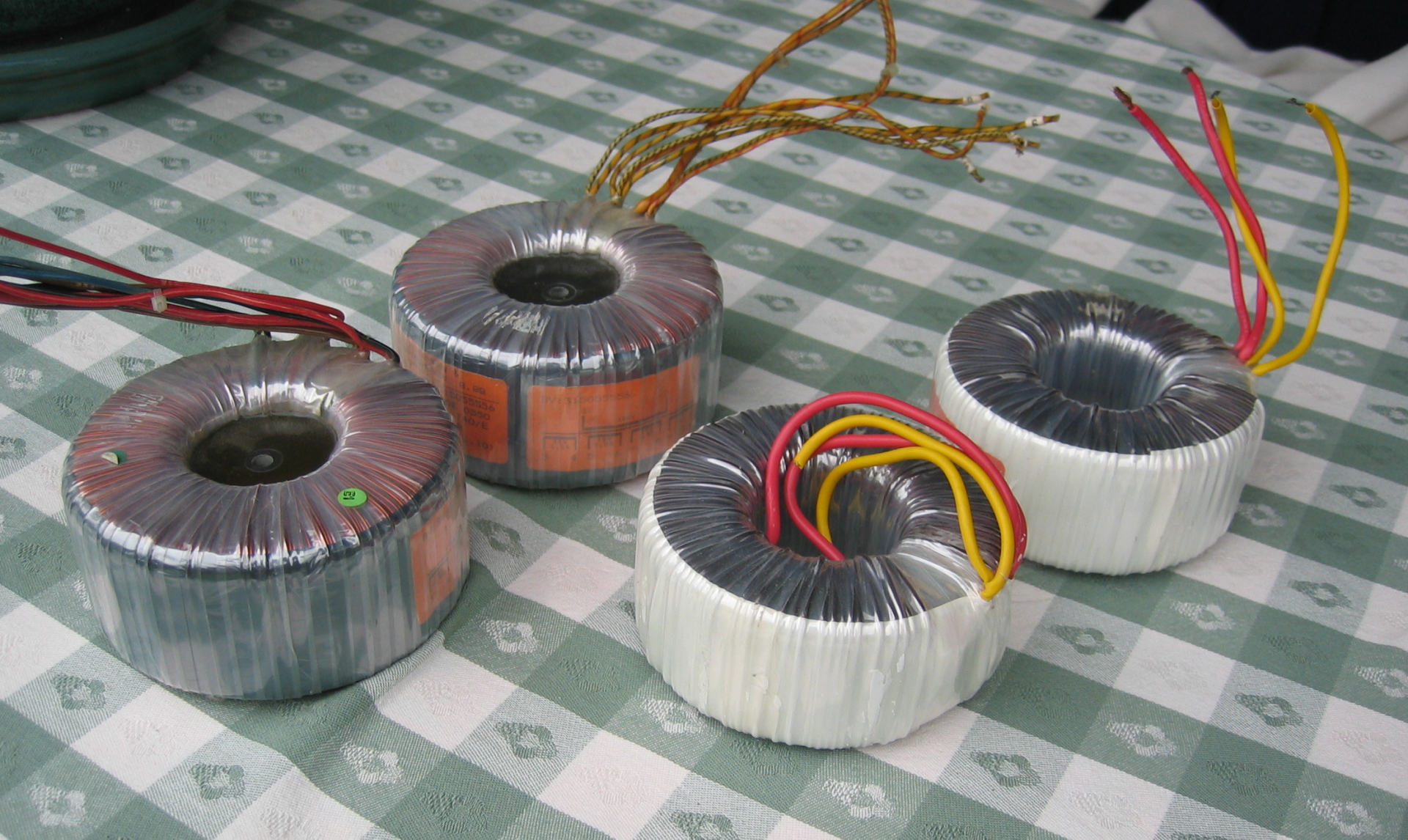
And, as with the coils that came before it, an enormous number of transformers are still wound, turn by turn, on a bench — which is the reason this dive exists in the form it does and gives so much room to the craft. The value one needs may not exist as a stock part; a vintage amplifier may want an output transformer no one has made in fifty years; a homebrew power supply, a ham-radio balun, or a piece of restored test gear may demand a custom winding on a particular core. Winding a transformer is a real skill — laying down the primary, interleaving insulation between layers, bringing out taps and leads, stacking and interleaving the E- and I-shaped laminations of the core, assembling a toroid by threading every turn through the ring, impregnating the finished part with varnish, and testing its insulation for safety — and it is a skill the builder can practice with the very same coil-winding machines used for inductors. The toroidal transformers in the photograph, with their wire wound directly onto ring cores, are among the most demanding and satisfying to wind by hand.
This volume has laid the whole foundation, and the thirteen ahead build outward from it. Volume two dismantles the ideal transformer and replaces it with the real one — leakage and magnetizing inductance, copper and core loss, inter-winding capacitance, regulation and efficiency. Volume three tells the history, from Faraday’s iron ring through the induction coil and the war of currents to the modern grid. Volume four goes deep on core materials and construction — grain-oriented silicon steel, laminations, the EI and toroidal and C-core shapes, ferrites and amorphous alloys, saturation and eddy currents and the air gap, extending the coils dive’s magnetics to the two-winding case. Volume five covers the magnet wire, the windings, and the safety-critical insulation systems that keep the mains and the user apart. Volume six revisits transformer action in depth — volts-per-turn, ampere-turn balance, the magnetizing branch, inrush, and saturation. Volumes seven and eight survey the whole family of types: power and audio transformers, autotransformers and the variac, isolation transformers; then instrument, RF, and switch-mode transformers, current and voltage transformers, baluns and ununs, and the flyback and forward transformers of switching supplies. Volume nine is the design volume, built around the EMF equation that sets volts-per-turn from core area and flux, area-product core selection, wire sizing, and regulation and temperature-rise budgets, with worked mains and ferrite designs. Volumes ten through twelve are the hands-on heart the builder came for: the winding machines set up for transformer work, the technique of actually winding your own, and a set of worked build-your-own projects from a mains rewind to an audio output transformer to an antenna balun. Volume thirteen is the bench-measurement volume — turns ratio, winding resistance, leakage and magnetizing inductance, the open- and short-circuit tests, phasing, hi-pot, regulation, and efficiency. And volume fourteen is the reference apparatus: the glossary, the equation cheat sheet, the core and lamination tables, the wire and safety tables, and the further reading. Every one of them rests on the one sentence this volume began with. A transformer moves energy from one circuit to another through a shared magnetic field, and in the crossing it trades voltage for current by the ratio of its turns — and from that single, elegant habit, the whole vast usefulness of the component unfolds.
Comments (0)