Transformers and Transformer Winding · Volume 10
The Winding Machines
10.1 From the coil bench to the transformer bench
The companion Coils dive devoted a whole volume to the coil-winding machines — the anatomy every winder shares, the four subsystems of spindle, counter, traverse, and tensioner, and the ladder from hand crank through motorised bench winder to CNC, with the toroid shuttle as the clever special case. None of that is repeated at length here, because a coil is a coil to the machine and the same winder that lays an RF choke lays a transformer’s primary. What this volume does instead is take those machines and point them at the particular demands of a transformer, which is a harder customer than a plain inductor in three specific ways, and then work through the setup and technique that those demands force. The reader who has not read the Coils machine volume will still be able to follow along — the essentials are recalled in passing — but the emphasis throughout is on what changes when the part on the arbor is a two-winding, safety-critical transformer bobbin rather than a single choke.
The three ways a transformer raises the stakes are worth stating up front, because they organise everything that follows. First, a transformer has more than one winding, and those windings must be laid down in sequence — primary, then insulation, then secondary, sometimes several sections deep — with the machine stopped and re-set between them. Second, a transformer’s turns count is not a rough target but an exact ratio: the whole point of the device is that the secondary voltage is the primary voltage scaled by N₂ divided by N₁, so an error of a few turns on either winding shifts the output and, on a multi-tap winding, lands the tap on the wrong voltage. Third, and most importantly, a mains transformer’s windings sit at lethal potential and the insulation between them is a safety barrier, so the machine must lay clean, even, predictable layers that the builder can reliably insulate over — the tidy layer winding that a random-wound choke never needs. A machine earns its place on the transformer bench precisely because it delivers repeatable turns, even layers, and steady tension, and it is those three that the rest of this volume is about.
10.2 Why a machine, even a simple one, beats the bare hand
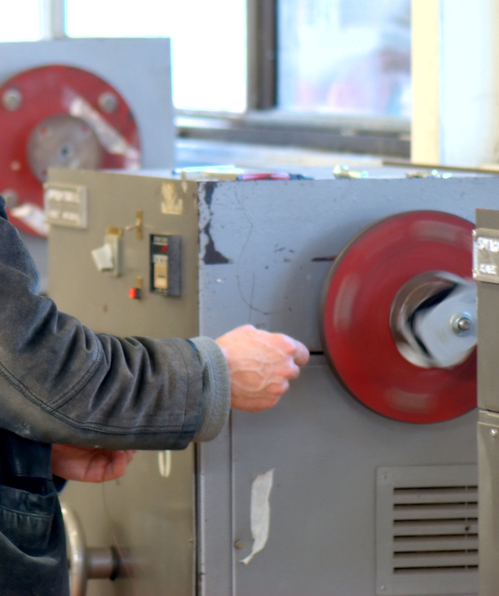
Wind a transformer entirely by hand — spool in one hand, bobbin in the other, counting under your breath — and every one of the three demands above fights you at once. The count is the first to go: inductance and turns ratio both hinge on N, and a person feeding wire while counting to several hundred loses the tally reliably, so the finished ratio is a guess. The lay is the second: a hand that wanders leaves gaps and climbs turns over one another, so the winding builds up unevenly, bulges past the bobbin flanges, and presents a lumpy surface that interlayer insulation cannot sit flat on. The tension is the third and quietest: a bare hand cannot hold constant pull for a thousand turns, so some turns are slack and spring loose while others are over-tight, drawing the copper thin and scraping the enamel against the bobbin’s edges.
A winding machine — even the humblest hand-cranked one with a mechanical counter — takes those three jobs off the human and makes them repeatable. The counter tallies every spindle revolution so the builder can wind exactly 312 turns and get exactly 312; the traverse (or a disciplined guiding hand) lays the turns side by side so the layers are even; and the tensioner holds steady back-tension so every turn seats firmly against its neighbour. That word repeatable is the whole argument. A one-off experimental transformer can be wound loosely and measured afterward, but a transformer that has to hit a design ratio, stack neat insulable layers, and — if it is one of a batch — match its siblings, needs the machine to take the human variability out of the loop.
None of this means the machine does everything. The opposite is true, and it is the theme of the volume that follows this one: the machine is brilliant at the mechanical, repetitive parts — turning, counting, laying, tensioning — and useless at the judgement parts. It cannot decide where a tap should come out, dress a lead so it survives handling, lay a strip of interlayer film flat and wrinkle-free, start and finish a winding so the ends are anchored and accessible, or know when a bobbin is packed too full to close the core. Those remain hand skills, and a good transformer is a partnership: the machine does the counting and the spinning, the builder does the thinking and the finishing. The machine is what makes the hand skills worth exercising, because there is no point dressing a beautiful tap on a winding whose turn count is wrong.
10.3 The machine classes, pointed at transformer work
The classes of winder are the same three the Coils dive laid out, and the fastest way to choose among them for transformer work is to see what each class does with the three transformer demands.
The manual hand winder is a spindle turned by a crank, a mechanical turns counter geared to that spindle, a means of holding the bobbin, and — on the better ones — a simple lead-screw traverse and a felt-pad tensioner. Its counter is usually an odometer-style drum of number wheels driven by a worm off the crank shaft: robust, needing no power, reading the running total at a glance, but able only to count, never to stop the machine. For transformer work the hand winder’s great virtue is control. Cranking by hand, the builder feels the wire’s tension directly, feels a snag the instant it happens, and can pause on the exact turn to bring out a tap or lay a strip of insulation without fighting a coasting motor. Its limits are equally plain: the arm sets the speed, so a thousand-turn mains primary is a thousand cranks, and because nothing stops the spindle automatically, hitting an exact high count means watching the drum and quitting at the right moment, with the ever-present risk of an overshoot. For the occasional transformer, a hand winder with an honest counter and a decent tensioner is genuinely enough.
The motorised bench winder puts a variable-speed motor on the spindle, controlled by a foot pedal so both hands stay free for the wire, and pairs it with a preset electronic counter. That counter senses each revolution with an optical slot or a Hall-effect sensor, tallies the pulses digitally, and — the feature that matters — decelerates the motor a few turns before the target and stops it dead on the count. This is the single most worthwhile machine for anyone who winds more than the odd transformer. A primary that took ten patient minutes by hand is wound in under one and comes out on count every time, because the machine, not a tiring shoulder, does the stopping. What the motorised bench winder usually does not automate is the wire lay — many leave the traverse to the operator’s hand — and that division of labour is exactly right for transformer work: the motor and preset counter kill the tedious, error-prone jobs of turning and counting, while the skilled hand keeps the delicate task of laying clean layers and dressing taps and leads.
The CNC or fully programmable winder commands the spindle motor and one or more traverse motors together, in closed loop, and often the tension as well. Nothing here is new in principle — it is still spindle, counter, traverse, tensioner — but every one is now a servo-controlled axis coordinated by software, and that coordination is what a complex transformer rewards. Because the traverse is a programmed axis synchronised to the spindle rather than a fixed gear ratio, a CNC winder can be told, in a stored program: wind this many turns at this pitch to make layer one of the primary; reverse and lay layer two; step over and start a second section; bring out a tap at this turn; stop here so the operator can lay interlayer tape; then wind the secondary. A transformer with a multi-tap primary, an interleaved primary-secondary-primary sandwich, and a centre-tapped secondary is exactly the sort of part whose turn-by-turn recipe a programmable machine executes identically every time. The trade is that the machine does not lay the insulation or dress the leads — those pauses are still hand operations even on a CNC machine — so a programmable winder shines when the winding itself is intricate and repeated, not when the finishing dominates.
10.3.1 The winders on this bench
The winding volumes of this project are written around real machines: the shop that occasions them keeps three computer-controlled coil winders — two bought secondhand and one built in-house — used for both the inductors of the Coils dive and the transformers of this one. Those machines and their capabilities live on the Model Shop’s Coil Winders pages, and the transformer-specific setups shown throughout this volume are meant to be read alongside them. The particulars of the owner’s own machines — their make and model, their counter and traverse arrangement, the range of bobbins they can practically hold — belong in the placeholders below, to be filled from the bench rather than invented.
10.4 The traverse: the heart of neat layer winding
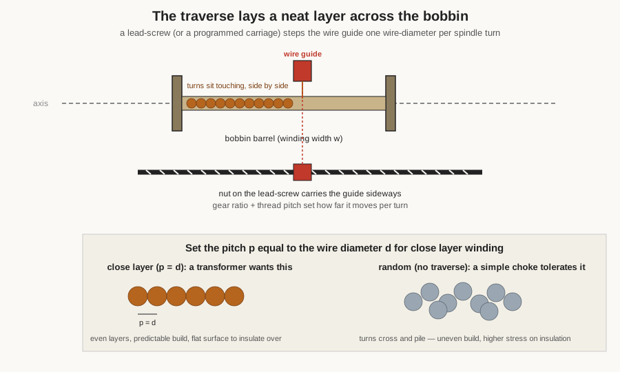
If one subsystem separates a transformer-capable winder from a motorised spool, it is the traverse, because the traverse is what turns a heap of wire into the tidy layers a transformer needs. Its job is to move the wire guide steadily along the bobbin’s width in step with the spindle’s rotation, so that as each turn is laid the wire has advanced by exactly one turn’s width — the pitch — and the next turn falls neatly beside it rather than climbing onto its neighbour.
The pitch is the whole game. Set the traverse so the guide advances by exactly one wire diameter per spindle revolution and the turns lie touching, packed as tightly as the enamel allows: a close-wound layer, the maximum turns across the bobbin width and a flat, even surface. That flat surface is not a cosmetic nicety. A transformer builds its windings in layers, and between layers — certainly between the primary and the secondary — goes a strip of insulating film or tape. That film can only sit flat and do its job if the layer beneath it is flat, and a layer is flat only if the traverse laid it evenly. A random-wound choke tolerates turns that cross and pile because it has one winding and no insulation barrier to keep flat; a transformer does not, which is why the traverse matters far more on the transformer bench than it does for a simple inductor. Set the pitch a little larger than the wire diameter and the turns are spaced with small air gaps — used for a high-voltage winding where a little turn-to-turn spacing eases the dielectric stress, or where a lower winding capacitance is wanted — but for the common run of transformer layers the target is a close-wound p equal to d.
On a mechanical machine the traverse is a lead-screw — a precision threaded rod — coupled to the spindle through a train of change gears, so that one spindle turn advances the guide by a fixed distance set by the gear ratio and the thread pitch. Swap the gears and the pitch changes; this is exact and repeatable but fiddly to alter, so many bench machines instead leave the traverse to the operator’s guiding hand, pacing the lay across the spinning bobbin by eye and feel. Hand traverse sounds crude and for wide, close-wound layers of fine wire it takes real skill, but it is how a great deal of small-shop transformer work is genuinely done: the machine spins and counts, the hand lays. The real power shows on a programmable machine, where the guide has its own stepper or servo and the pitch is a number in software, changeable turn by turn. Now the machine can wind a precise number of layers, reverse the traverse at each end to build a multilayer winding, step over a controlled distance to begin a new section, and change pitch mid-winding — laying a fine secondary at one pitch over a coarse primary wound at another, all without a gear change. For a transformer with several windings of different wire gauges, that software-set pitch is what lets one machine wind them all cleanly.
10.5 Tension: the quiet subsystem that decides fill and safety
Tension is the subsystem beginners ignore and experts obsess over, because it is invisible until the winding is finished and then it is the first thing that shows. On a transformer its consequences are more than cosmetic. Too little tension and the turns are loose and sloppy: they spring away from the bobbin, bulge past the flanges, and cross over one another, so the winding builds up thicker than the design’s window budget allows — and a transformer that will not fit back inside its core, or whose bulging primary leaves no room for the secondary and its insulation, is a failed transformer. Too much tension and the trouble is worse: the copper is drawn thinner so its resistance rises, the enamel is scraped or crushed against the bobbin’s edges — nicking the very insulation that on a mains winding is a safety barrier — thin secondary wire snaps outright partway through a long winding, and the accumulated squeeze of hundreds of tight turns can crack a light plastic bobbin. What the wire wants is constant tension: enough to seat each turn firmly, the same on turn one and turn one thousand, without slack and without stretch.
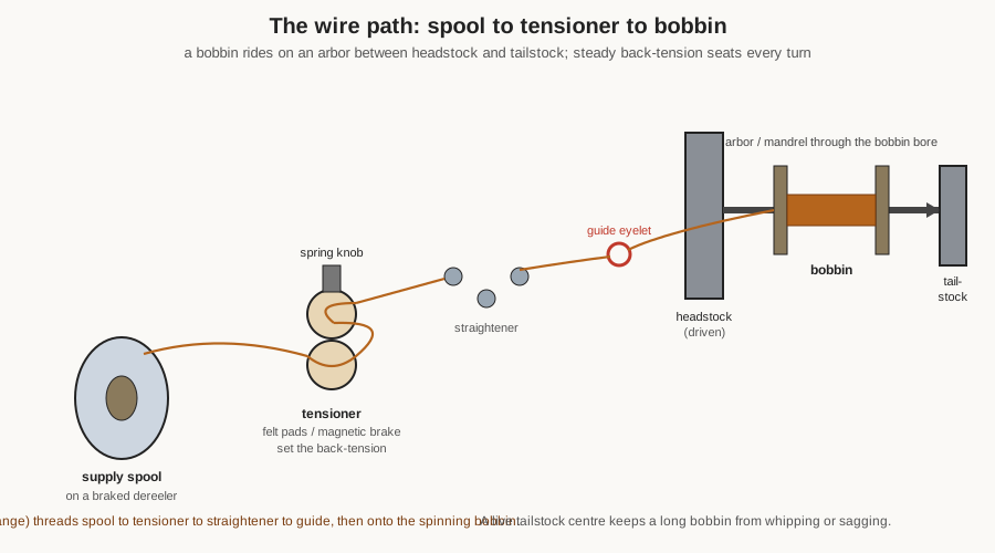
The simplest tensioner is a felt-pad or disc arrangement, the wire threaded between two spring-loaded pads whose pinch a knob sets. It is cheap, compact, and on countless bench winders entirely adequate; its weakness is that friction drag varies with speed and with how much wire is left on the supply spool, so the tension is not truly constant as the machine accelerates and the spool empties. A refinement is the spring dancer arm, a pulley on a pivoted spring-loaded arm that swings to swallow slack and give back wire when the pull increases, mechanically averaging out the jerks and snags that would otherwise yank fine wire. The high end is the magnetic tensioner — a hysteresis or magnetic-particle brake on a capstan the wire wraps around — whose drag is set electrically, is essentially constant regardless of speed, can be programmed and even ramped, and has no friction surface to wear or damage the finest wire. These sealed magnetic brakes are what CNC machines use, often with a load cell measuring the actual wire tension and the controller closing the loop by trimming the brake current. Feeding all of them is the dereeler, the supply-spool holder, which on a good machine brakes the spool so it cannot overrun and dump a loop of slack when the machine decelerates. A useful rule of thumb the winding literature repeats is to run the tension at roughly ten to twenty per cent of the wire’s breaking strength — firm enough to seat the turns, gentle enough to leave a margin against snapping — and to reduce it deliberately for the finest secondary wire, where the margin is thinnest.
10.6 Holding the part: arbors, mandrels, and long bobbins
Before a machine can wind anything it has to hold the bobbin and spin it true, and the transformer shop’s bobbins come in a wide range of shapes: a moulded plastic former with a rectangular centre hole for an EI core, a longer split bobbin with a moulded partition between primary and secondary chambers, a small ferrite bobbin for a switch-mode part, a bare toroid ring with no shaft at all. The spindle end adapts with a small family of fixtures. The commonest is an arbor or mandrel: a shaft, often stepped to match a family of bobbin bores, that slides through the bobbin’s centre so the bobbin turns with the shaft, clamped between shoulders or by a nut. Because a transformer bobbin’s bore is usually rectangular rather than round — it has to match the core’s centre leg — the arbor for it is a matching rectangular or stepped mandrel, sometimes a shop-made one turned and milled to fit a particular bobbin, or a proprietary adapter that clips the moulded bobbin onto a round spindle.
Two practical points matter more for transformers than for small coils. The first is balance. A transformer bobbin loaded with a heavy copper winding, spun at speed, will vibrate and whip if it is mounted off-centre, throwing off the lay and stressing the spindle bearings; the arbor must hold the bobbin concentric and the machine must be run at a speed the loaded assembly can take smoothly. The second is support for long bobbins. A mains transformer’s bobbin can be several inches wide, and a wide bobbin cantilevered off a single spindle end sags and whips. The answer is the tailstock — a supporting centre at the far end that takes an arbor point, so the bobbin is held at both ends like work in a lathe and cannot flex. A well-equipped transformer bench accumulates a drawer of arbors, adapters, and shop-made jigs for the particular bobbins it winds; building or buying the right holder for an awkward bobbin is often what turns a frustrating job into a routine one.
10.7 Counting and tapping: stopping exactly where the design says
The turns counter is, if a transformer winder had to be reduced to one instrument, the one it would be, because on a transformer the count is the ratio. A mechanical counter — the odometer drum geared off the spindle — reads the running total at a glance, needs no power, and is entirely adequate for a hand winder, but it only counts; the operator must watch it and stop cranking on the number. An electronic counter senses each revolution digitally, shows a bright unambiguous readout, and — the transformer-making feature — accepts a preset: dial in the target and the machine decelerates and halts on the exact turn. Better controllers count turns per section, so a winding can be programmed as a sequence of targets — wind to turn 240 and stop for a tap, continue to turn 480 and stop for the layer change, and so on — with the counter tracking not one total but the whole recipe.
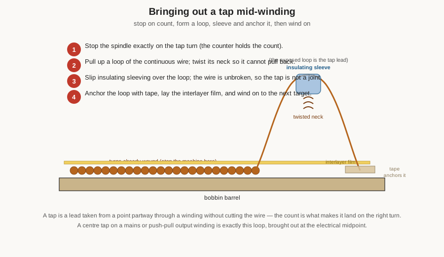
That preset-and-stop ability is what makes precise tapping possible. A tap is a lead taken from a point partway along a winding without cutting the wire, so the winding continues unbroken past it. To bring one out, the machine is stopped exactly on the tap turn — the counter is what lands it on the right turn, and hence the right voltage — a loop of the continuous wire is pulled up, its neck twisted so it cannot pull back, insulating sleeving is slipped over the exposed loop, and the loop is anchored with tape before winding resumes. Because the wire is never cut, the tap is not a soldered joint buried in the winding; it is a continuous conductor with a serviceable lead brought out. A mains primary with 230-volt and 240-volt taps, a secondary with a centre tap for a full-wave rectifier, a push-pull output transformer’s centre-tapped primary — all are this same loop, brought out at the turn the design calls for, and all depend on the counter to put it in the right place. Multi-section windings, where a single winding is split into two or more chambers of a split bobbin to reduce its self-capacitance or to spread it either side of a secondary, are the same idea taken further: the counter tracks the turns per chamber, and the traverse steps the wire over to the next chamber at the programmed count.
10.8 Interleaving on the machine: the pauses that make a transformer
Everything so far describes laying one winding. A transformer is defined by having more than one, and the machine’s role in a multi-winding build is as much about the pauses as the winding. The sequence for a typical mains transformer runs: wind the primary to its full turn count, laying interlayer film between its layers as it builds; stop; lay a barrier of insulation over the finished primary — several turns of tape, or a wrap of film heavy enough to be the safety barrier between line and user; then wind the secondary over that barrier, again interleaving between its layers; stop; and finish with an outer wrap. Each of those “stop and insulate” steps is a pause in the machine’s program, a moment where the spindle is halted on count and the operator lays insulation by hand before restarting.
The interlayer and inter-winding insulation itself is the subject of an earlier volume and is not re-derived here; what matters for the machine is that it must stop cleanly and hold its count through the pause. A hand winder does this naturally — the builder simply stops cranking, lays the tape, and resumes, the mechanical counter holding its total. A motorised bench winder needs a counter that pauses without losing count, which any preset electronic counter does. A programmable machine can have the pauses built into the program, halting automatically at each layer or winding boundary and prompting the operator to lay insulation before it will restart, which on a repeated build removes the risk of forgetting a barrier. The technique of laying the film flat and wrinkle-free, of keeping the margins clear at the bobbin ends for creepage, of choosing where to interleave a primary-secondary-primary sandwich to cut leakage inductance — all of that is hand craft and belongs to the winding-technique volume that follows. The machine’s contribution is narrow but essential: it lays each layer flat enough to insulate over, and it holds the count through every pause so the ratio survives the interruptions.
10.9 Toroid winders: a fundamentally different machine
Some transformer cores defeat the ordinary spindle-and-traverse machine entirely, and the toroid is the archetype. A toroid is a closed ring, and a closed ring has no axis to put a spindle through, because the wire has to pass through the ring’s central hole on every single turn and a spool of wire will not fit through the hole. Winding a toroid by hand means cutting a length of wire, threading its whole length through the hole, pulling it snug, and repeating — dragging the entire remaining wire through the donut, turn after turn. It is the most tedious job in the whole craft, and it cannot be done on a normal winder at all: no arbor grips a ring, no spindle can spin it, no ordinary traverse applies. The toroid therefore has its own class of machine, built around the awkward geometry.
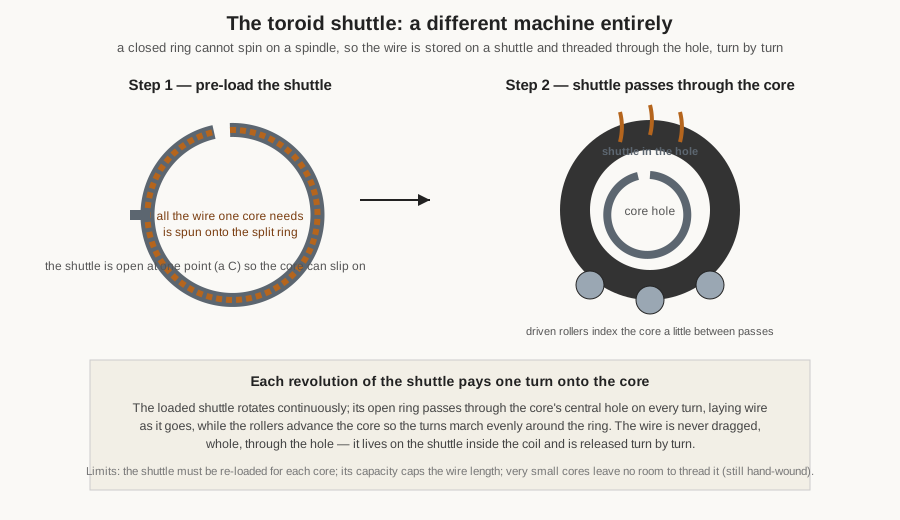
The trick is a shuttle — a split ring, open at one point like the letter C — that is first pre-loaded with all the wire one core will need, spun onto it in a first operation. The loaded shuttle is then threaded through the toroid’s central hole (the gap in the C lets the core slip on and off), and there it rotates continuously, its open ring passing through the core’s hole on every revolution. Each pass pays a length of wire off the shuttle and lays it as one turn on the core, while a nest of driven rollers turns the core a little between passes so the turns advance evenly around the ring. The genius of the scheme is that the wire no longer has to be dragged, whole, through the hole each turn; it is stored on the shuttle inside the loop of the coil and released turn by turn. A toroid that would take an hour by hand is wound in a minute or two. This is the machine class that firms such as Jovil Universal have built for decades — microprocessor-controlled toroidal winders with interchangeable winding heads, stepper-motor core indexing, and programmable turns and pitch — and it is genuinely a different machine from the bench winder, sharing only the underlying idea of a counted turn laid under controlled tension.
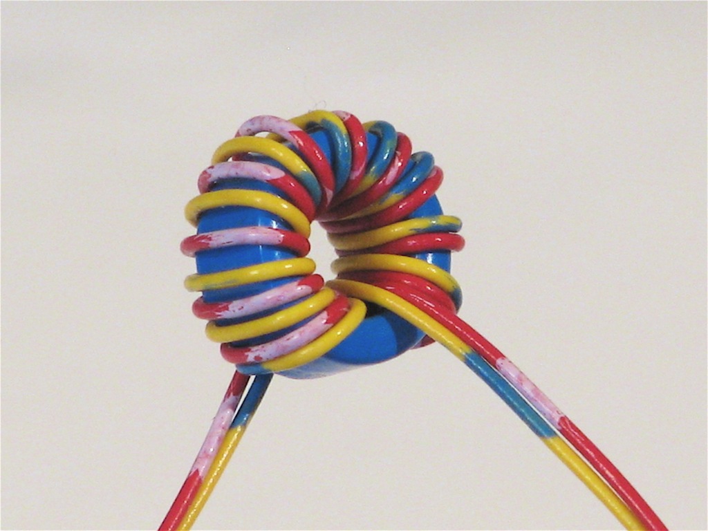
The costs of the shuttle scheme set its limits, and they matter to the transformer builder choosing whether to machine-wind a toroid at all. The shuttle must be re-loaded for each core, a separate operation. Its capacity caps the total wire length it can hold, and hence the number of turns and the wire gauge that can be wound in one go — a heavy-gauge, high-turn toroid may exceed what a shuttle will carry. And there must be room to thread the shuttle through the hole, so very small toroids, whose holes are too small to admit a shuttle, remain genuinely hard to machine-wind. This is why the smallest ferrite toroids — the RF transformers, the baluns and ununs, the little common-mode chokes — are so often still wound by hand, patiently threading the wire through turn by turn, a technique the build-your-own volumes take up in detail. For the larger toroidal power transformer, by contrast, the shuttle machine is exactly the tool, and its clean even lay around the ring is part of why a toroidal power transformer runs so quietly.
10.10 Setup, speed, safety, and when to wind by hand
Setting a machine up for a transformer job is a short discipline that pays for itself. The right arbor or adapter is chosen and the bobbin mounted concentric and, if wide, supported at the tailstock. The correct wire spool goes on a braked dereeler and the wire is threaded through the tensioner and guide, the tension set to seat the turns without stretching them. The counter is zeroed and the target — or the whole sequence of targets for a multi-section, multi-tap winding — is dialled in or programmed. The traverse pitch is set to the wire diameter for a close layer, or left to a practised hand. Only then does the machine run, and it runs at a speed the loaded bobbin can take smoothly: fine secondary wire and a light bobbin want a gentle speed, because a fast machine snaps thin wire and a coasting spindle overshoots a tap. The preset counter’s deceleration band matters here — a machine that sprints through the bulk of a winding and then slows to crawl onto the exact tap turn gives both speed and precision, where a machine that runs flat out to the last turn will overshoot.
The safety points are few but real. The spinning spindle, the moving wire, and the foot-pedal control are a place to keep fingers, loose sleeves, and long hair clear; fine magnet wire under tension will cut skin if a hand fouls it. On a mains transformer the far larger hazard is downstream — the insulation system that keeps line potential off the user — and the machine’s contribution to that safety is indirect but genuine: even, well-tensioned layers are what let the interlayer and barrier insulation sit flat and unbroken, so a tidily machine-wound transformer is a safer transformer than a lumpy hand-wound one, quite apart from being a more accurate one. The hi-pot test that later proves the barrier, and the creepage margins kept at the bobbin ends, are covered in the technique and testing volumes; the machine’s job is to give them a clean winding to work with.
When, then, should the builder set the machine aside and wind by hand? The honest answer is: for the parts the machine is bad at and the hand is good at. A very small toroid whose hole will not admit a shuttle is hand-wound because no machine can thread it. A one-off experimental transformer of a few dozen turns may be quicker to wind by hand than to set a machine up for. A winding with an unusual dressing — a special lead, an odd tap, a bifilar pair that must stay perfectly paired — may want the direct control of the hand for that stretch even on a machine-wound part. And the finishing of every transformer — the taps, the leads, the interleaving, the anchoring, the terminations — is hand work regardless of how the turns were laid. The machine and the hand are not rivals; the machine wins the count and the lay and the tension, the hand wins the judgement and the dressing, and a good transformer uses both.
10.11 Where this leads
This volume has taken the winding machines the Coils dive laid out and pointed them at the transformer’s three harder demands: an exact turns ratio that the counter must hit, tidy insulable layers that the traverse must lay, and steady tension that packs the copper without nicking the safety-critical enamel. It has walked the classes — the tactile hand winder, the foot-pedalled motorised bench winder with its decelerating preset counter, and the programmable CNC machine that executes a multi-winding, multi-tap recipe identically every time — and it has singled out what a transformer adds: the arbor and tailstock that hold a long rectangular-bore bobbin true, the counting-and-tapping that lands a lead on the right turn, the stop-and-insulate pauses that build a two-winding part, and the wholly separate shuttle machine that alone can wind a closed toroid. Throughout, the division of labour has held: the machine does the mechanical, repeatable work, and the hand does the judgement and the finishing.
That finishing is the next volume’s subject. Here the machine has been set up and understood; next the builder actually runs it — preparing the bobbin, winding the primary and laying its layers, interleaving the insulation, bringing out the taps and dressing the leads, building the secondary over the barrier, stacking and interleaving the EI laminations or assembling the toroid, and finishing with varnish and the hi-pot test that proves the safety barrier. The machine has been laid out on the bench and taken apart in the mind. Next, the winder threads the wire and starts the spindle, and the worked builds that follow put these machines to work on real transformers.
Comments (0)