Transformers and Transformer Winding · Volume 5
Magnet Wire, Windings, and Insulation
5.1 Where the copper meets the danger
Every earlier volume treated a transformer’s windings as clean abstractions: a primary of N₁ turns, a secondary of N₂ turns, a ratio that trades volts for amps. This volume is about the physical things those turns are actually made of — the varnish-brown enamelled copper, the whisper-thin films of polyester and polyimide, the sheets of Nomex and Kraft, the tape wound around the ends of a bobbin — and about the single fact that sets a transformer apart from a plain inductor: it has two windings that must be tightly coupled magnetically while, in a great many cases, being kept ruthlessly apart electrically. On a mains transformer the primary sits at line potential, hundreds of volts able to source lethal current, and the secondary is the thing a human being touches. The stuff in between — the enamel on the wire, the interlayer film, the bobbin, the margin tape — is not packaging. It is the safety barrier, and it is the load-bearing subject of this volume.
The Coils dive already covered magnet wire in its own right: what enamelled wire is, the American Wire Gauge system, the enamel films, skin and proximity effect, and Litz construction. That material is not repeated here except in brief. What a transformer adds — the part a single-winding inductor never has to face — is the insulation system that separates one winding from another and, above all, separates the mains from the user. Get the wire gauge wrong on an inductor and it runs hot. Get the insulation system wrong on a mains transformer and it can kill. This volume treats the wire choices quickly and the insulation and isolation at length, because that is where the real engineering, and the real hazard, live.
5.2 Magnet wire, revisited for two windings
Magnet wire — enamelled wire, winding wire, coil wire — is a solid copper conductor coated with a thin cured-polymer film that serves as turn-to-turn insulation. The word “enamel” is a historical holdover from the oleoresinous varnishes of a century ago; every modern film is a synthetic polymer baked on in successive passes. The Coils dive explains why the film is measured in microns rather than the millimetres of hook-up-wire jacket: a winding is a race to pack copper into a fixed window, and every micron of film is copper that did not fit. All of that carries over unchanged to a transformer. What changes is that a transformer stacks the requirements. The film on the primary must hold off the turn-to-turn voltage of the primary; the film on the secondary must hold off the secondary’s; and in a switch-mode transformer the first few turns of the primary can see the full fast edge of the switching waveform land across a handful of turns, so those turns’ film must survive repetitive high-dV/dt stress that a mains winding never sees.
5.2.1 Build: single, heavy, and triple
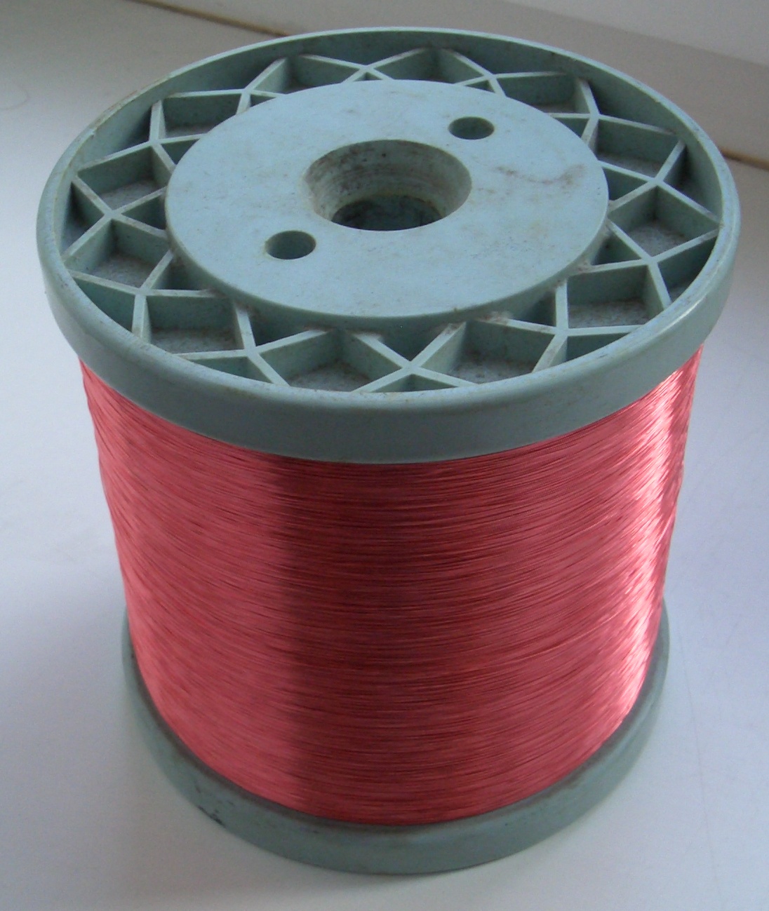
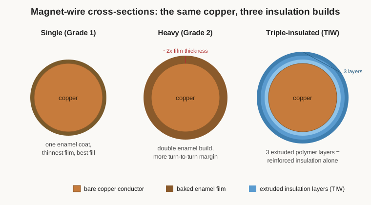
Enamel is applied in a controlled number of passes, and the total film thickness is graded. In the NEMA MW 1000 vocabulary the common grades are single build (sometimes “Grade 1”), heavy build (“Grade 2”), and triple build (“Grade 3”). Heavy build is, to a good approximation, twice the film thickness of single build on the same bare copper; triple build is thicker still. The trade is the obvious one: more film means more dielectric withstand between turns and better abrasion resistance during winding, at the cost of a larger overall diameter and so a poorer fill factor. For most transformer secondaries and low-voltage primaries a single build is fine. Heavy build earns its keep on high-voltage windings, on the first layers of a flyback primary, on anything wound on a rough former, and anywhere the winder wants insurance against a scrape that would otherwise short two turns. Figure 1’s spools would be labelled with both a gauge and a build; ordering “36 AWG” without saying single or heavy leaves the most important insulation number unspecified.
5.2.2 Thermal class: how hot the film can live
A transformer’s windings run warm — copper loss plus core loss dumps heat into the very region where the insulation lives — so the film is rated not by a single breakdown voltage but by a thermal class, the temperature at which the material holds a defined fraction of its properties over a defined service life (conventionally 20,000 hours). The classes come from IEC 60085 and are shared across the whole insulation industry. Each has a letter and a temperature:
Table 1 — insulation industry. Each has a letter and a temperature
| Class letter | Temperature index | Typical wire enamel at this class |
|---|---|---|
| A | 105 °C | oleoresinous / plain enamel (legacy) |
| E | 120 °C | early polyurethane, PVA formvar |
| B | 130 °C | polyurethane (solderable) |
| F | 155 °C | polyester, modified polyurethane |
| H | 180 °C | polyester-imide (PEI) |
| N | 200 °C | polyester-imide overcoated with polyamide-imide |
| R | 220 °C | polyester or PEI base + polyamide-imide (PAI) topcoat |
| S | 240 °C | polyimide (aromatic, e.g. ML / Kapton type) |
Figure 8 — Insulation thermal classes (IEC 60085) and the wire enamels that typically meet each. Temperature index is the material’s rated continuous hot-spot temperature.
The chemistry tracks the temperature. Solderable polyurethane enamel is the hobbyist’s friend: heated in a solder pot at roughly 380–400 °C the film chars and clears, so the winder can tin a lead without scraping it. Polyurethane tops out around Class B to F. Polyester (PE) and polyester-imide (PEI) climb into Class F, H, and N with better mechanical toughness and heat life, at the price of needing a scrape or a hotter pot to strip. The very high classes are built as a composite: a tough polyester or polyester-imide base coat for body and flexibility, overcoated with a thin polyamide-imide (PAI) topcoat that adds chemical, abrasion, and thermal resistance — the “PEI/PAI” system that reaches Class 200 and 220. At the top, aromatic polyimide (the ML or Kapton-type films) reaches Class 240 and is chosen for aerospace and corona-resistant windings, at a price and with a film that will not solder at all. For a bench winder the practical rule is: pick the lowest class that survives the transformer’s hottest expected spot with margin, and prefer a solderable grade wherever the terminations will be hand-soldered, because a film that will not tin turns every lead into a scraping chore.
5.2.3 Self-bonding and triple-insulated wire
Two transformer-relevant specialty wires deserve a note. Self-bonding wire (also “bondable” or “baked” wire) carries an extra outer coat of a thermoplastic or thermosetting adhesive over the normal enamel. After winding, the coil is heated — by an oven, a current pulse, or a solvent — and the adhesive fuses adjacent turns into a solid, self-supporting block. This is how a coil holds its shape with no bobbin at all, and it is invaluable for air-cored RF windings and for small transformers that must survive vibration; the winding becomes a rigid monolith instead of a loose helix.
Triple-insulated wire (TIW) is the piece of magnet wire that changed switch-mode transformer construction, and it is a genuine safety component rather than a convenience. Instead of a single enamel film, TIW carries three concentric, separately extruded insulating layers over the copper — commonly a polyester, polyamide, or fluoropolymer system — each layer individually rated to withstand a basic level of insulation, so that the three together are certified as reinforced insulation all on their own. The consequence is large: a transformer wound with TIW on the primary or secondary can place the two windings physically adjacent, layer against layer, with no margin tape and no barrier tape between them, because the wire is the barrier. The three layers meet the reinforced-insulation requirements of the modern safety standard IEC 62368-1, Annex J (the role previously served by IEC 60950-1 Annex U and, for medical equipment, IEC 60601 Annex L). This is why an offline USB charger the size of a matchbox can still be a properly isolated, double-insulated mains appliance: TIW buys back the volume that margins and barrier tape would otherwise consume. A related product, fully-insulated wire (FIW), uses multiple thinner extruded layers to the same reinforced rating with a smaller overall diameter, recovering copper fill; both are permitted as reinforced insulation under the current standards. The winder who reaches for TIW is not saving space for its own sake — they are moving the safety barrier off the bobbin and onto the wire, and the certification follows the wire.
5.3 The windings: primary, secondary, taps
A transformer has, at minimum, a primary — the winding driven by the source — and one or more secondaries that deliver the transformed output. The turns of each come straight from the design equations developed in Volumes 1, 6, and 9: the volts-per-turn is fixed by the core, the frequency, and the flux density through the EMF equation, and then each winding’s turn count is simply its rated voltage divided by that volts-per-turn, with a few percent added to the secondary to cover the winding’s own resistive drop under load (the regulation the design volume quantifies). A 230-volt-to-12-volt transformer is not wound to an exact 19.2:1 ratio; the secondary is given extra turns so that, after its copper drop at full current, it still delivers 12 volts. That book-keeping belongs to Volume 9. What this volume cares about is that those numbers become real copper laid onto a former in a definite order, and that the order matters.
5.3.1 Winding order and why
For a line-frequency power transformer the usual practice is to wind the low-voltage / high-current winding innermost, closest to the core, and the high-voltage winding outside it. Two reasons drive this. First, the innermost layers sit on the smallest circumference, so putting the high-current winding there gives it the shortest mean-length-per-turn and therefore the least copper resistance and loss, exactly where the current is largest. Second, it keeps the highest-voltage copper away from the grounded core, easing the insulation problem to the core. There are counter-arguments — sometimes the primary goes innermost so that a fault to the core trips the supply-side protection — and the choice is genuinely a design decision, not a law. The point for the winder is that the order is chosen, recorded, and followed, because it sets both the loss budget and the isolation geometry.
5.3.2 Bifilar and multifilar winding
Some windings are laid down not one wire at a time but two or more wires in parallel and side by side, wound together as if they were a single ribbon. This is bifilar winding (two wires) or multifilar (more). It has three distinct uses in transformers. When the two wires are then connected in parallel, it is simply a way of handling a large current with two thinner, more manageable wires that pack and bend better than one fat one, and that share the high-frequency current more evenly. When the two identical wires are used as two separate windings, bifilar winding guarantees they have the same turn count and see nearly identical flux, which is exactly what a centre-tapped push-pull transformer, a matched pair of secondaries, or a 1:1 isolation winding wants — the tight coupling and matched leakage of the two halves come for free because the wires literally share the same turns of the same helix. And in radio-frequency and transmission-line transformers, bifilar and trifilar windings on a ferrite binocular core are the basis of baluns and ununs, a topic Volume 8 develops. The winder should note the hazard buried in bifilar work: two adjacent bifilar wires can sit at very different potentials — the two ends of a high-voltage secondary, for instance — and then the full winding voltage appears across a single thickness of enamel between two touching turns. Bifilar winding is for tightly coupled, similar-potential wires; it is emphatically not a way to wind a mains primary against a low-voltage secondary.
5.3.3 Taps
A tap is a connection brought out from a chosen point partway along a winding, giving access to a fraction of its turns. Primary taps let one transformer suit several line voltages (a 220/230/240 selector, or the 115/230 series-parallel pair on a universal-input supply); secondary taps give multiple output voltages or a centre tap for full-wave rectification and push-pull stages. Mechanically a tap is a loop of the winding wire brought out to a pin or lead at the exact turn the design calls for, and it is one of the more error-prone moments in winding because a tap one layer early or late changes the ratio and, on a mains primary, changes the flux density and the running temperature. Volume 10’s winders count turns precisely partly so that taps land where the arithmetic says they should.
5.4 Coupling, interleaving, and the electrostatic shield
The magnetic coupling between primary and secondary is never perfect. The flux that links one winding but not the other is leakage flux, and it behaves in the circuit exactly like a series inductor in each winding — the leakage inductance that Volume 2 put into the equivalent circuit. Leakage inductance softens a power supply’s regulation, rings against stray capacitance to make switching spikes, and limits the bandwidth of an audio or pulse transformer. The winder’s most powerful tool against it is the physical arrangement of the windings, and that tool is interleaving.
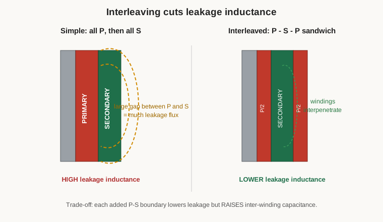
In a simple build — all of the primary wound first, then all of the secondary on top — the two windings occupy separate radial zones, and the leakage flux threads the gap between them. Interleaving breaks each winding into sections and stacks them alternately: a common arrangement winds half the primary, then the whole secondary, then the other half of the primary, the classic P-S-P sandwich of Figure 3. Because leakage inductance falls roughly with the square of the number of interfaces between primary and secondary, a single sandwich can cut it to a quarter of the simple value, and more sections cut it further. The technique simultaneously reduces the high-frequency proximity-effect copper loss, because it lowers the peak magnetomotive force reached inside the winding stack. This is standard practice in switch-mode and audio transformers, where leakage is a first-order enemy.
Interleaving is not free. Every added primary-to-secondary boundary is a new pair of closely spaced conductors at different potentials, so it raises the inter-winding capacitance. More capacitance means more common-mode noise coupled straight through the transformer and, in an offline supply, more leakage current to the chassis — exactly the thing a safety transformer is trying to prevent. So interleaving trades leakage inductance against inter-winding capacitance, and the designer chooses the number of sections to balance the two for the application: an audio output transformer may interleave heavily for bandwidth; a medical isolation transformer may interleave little, to keep the through-capacitance and leakage current tiny.
Where inter-winding capacitance must be tamed without giving up interleaving, the answer is a Faraday shield (an electrostatic screen): a single layer of copper foil, or a single-layer winding of fine wire, placed between primary and secondary and connected to a defined potential (chassis or a quiet ground). It intercepts the capacitive displacement current that would otherwise flow from primary to secondary and shunts it to ground, dramatically reducing common-mode noise transfer. The shield carries one iron rule: it must not form a closed turn. A foil wrapped all the way around and overlapping onto itself is a shorted single-turn secondary, and it will draw enormous current and burn. The foil is cut so its ends overlap with insulation between them but do not touch electrically, and only one point is taken out to the ground lead. A correctly made Faraday shield is one of the marks of a well-engineered isolation or switch-mode transformer.
5.5 The insulation system: the heart of the volume
Here is the single most important idea in transformer construction, and the one most often misunderstood by beginners: a transformer’s isolation is not a component, it is a system. No single part is “the insulation.” The barrier that keeps the mains off the user is built from several materials acting together, and it is rated, tested, and certified as an assembled system, not part by part. Safety agencies recognise an “insulation system” — a specific named combination of wire enamel, interlayer material, bobbin, tape, and impregnating varnish, all qualified together to a thermal class and a dielectric rating. Substitute one material for a “similar” one and the certification is void, because the system was tested as a whole.
The layers of that system, working outward from the copper, are:
- the enamel film on the wire itself (turn-to-turn insulation);
- the interlayer insulation — sheets of polyester film, aramid paper (Nomex), or Kraft paper laid between layers or between windings (layer-to-layer and winding-to-winding insulation);
- the bobbin (also called the former or coil-former), the moulded insulating frame the winding sits on, which separates the whole winding from the core and, in a split bobbin, separates primary from secondary;
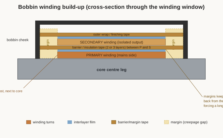
- the margin tape and barrier tape — tape wound at the ends of a winding (margins) and between primary and secondary (barrier) to build the required creepage and clearance and the required number of insulation layers.
5.5.1 Functional, basic, supplementary, double, reinforced
Safety standards grade insulation not by what it is made of but by what job it does, and every winder building mains equipment needs the vocabulary:
- Functional insulation exists only to make the circuit work — the enamel between adjacent turns of the same winding. It carries no safety duty; if it fails, the transformer misbehaves but no one is protected by it.
- Basic insulation provides one level of protection against electric shock — a single barrier between a hazardous voltage and an accessible part.
- Supplementary insulation is a second, independent barrier added specifically so that if the basic insulation fails, protection remains.
- Double insulation is basic plus supplementary together — two independent barriers, so that no single failure exposes the user.
- Reinforced insulation is a single insulation system that is qualified to the same level of protection as double insulation. TIW is the classic example: one wire, but rated equal to two independent barriers.
For a mains transformer feeding a low-voltage output that a person can touch, the primary-to-secondary barrier must be double or reinforced insulation. That is the whole reason margins, barrier tape, and TIW exist: they are how the winder physically realises a double or reinforced barrier between the line-voltage copper and the copper the user contacts.
5.5.2 Creepage and clearance
Two distances quantify how far apart the two sides of a barrier must be, and they are not the same distance:
- Clearance is the shortest distance through air between two conductors — the path a spark would jump.
- Creepage is the shortest distance along the surface of the solid insulation between the same two conductors — the path a tracking discharge would crawl, following the bobbin wall, the tape, the potting.
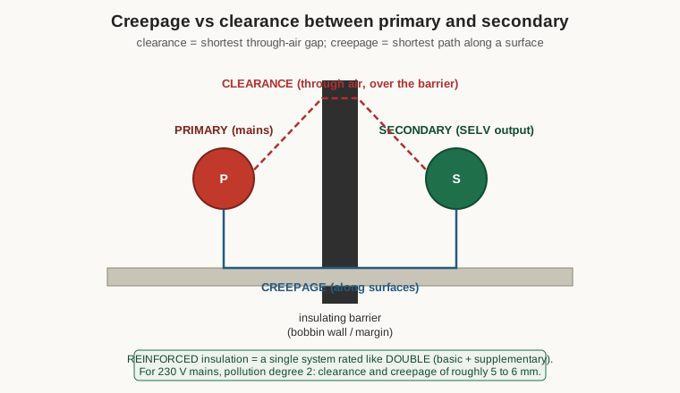
Clearance is set mainly by the peak working voltage and the expected transient overvoltage: enough air that neither the working voltage nor a mains surge arcs across. Creepage is set by the working voltage and by two environmental facts. The first is pollution degree — how much conductive dust and moisture can settle on the surface. Most equipment interiors are pollution degree 2 (normally only non-conductive pollution, occasional condensation). The second is the material group of the insulator, ranked by its Comparative Tracking Index (CTI), a measure of how well the surface resists forming a carbonised conducting track: Group I (CTI ≥ 600) is the most tracking-resistant, down through Groups II, IIIa, and IIIb (CTI 100–175) which need the most creepage for the same voltage. A dirtier environment or a poorer-tracking material demands more surface distance for the same volts.
Concrete numbers anchor the abstraction. For basic insulation at a 230-volt mains working voltage, pollution degree 2, a typical creepage requirement is on the order of 2.5 to 4 mm depending on material group, with a clearance of roughly 1.5 to 2.5 mm. For reinforced insulation the figures are essentially doubled — a creepage of roughly 5 to 6.4 mm and a clearance of several millimetres between the primary and any user-accessible secondary. These are the numbers the margins in Figure 4 are built to satisfy: the margin tape holds the copper back from the bobbin end so that the surface path from primary to secondary, crawling up over the tape and down the other side, is long enough to meet the reinforced creepage figure. A leaded bobbin transformer that skimps on margins is not “close enough” — it is out of spec, and the deficit is invisible until it fails.
5.5.3 Margins versus triple-insulated wire
There are two accepted ways to build the reinforced primary-to-secondary barrier, and they are alternatives, not additions. The margin-tape method wraps a band of tape at each end of the winding width so the primary and secondary coppers physically stop several millimetres short of each other along the bobbin, and lays two or three layers of barrier tape radially between the windings; the margins provide the creepage, the barrier tape provides the through-insulation layers. It is robust, cheap, and universal on line-frequency and larger switch-mode transformers, at the cost of the winding window the margins consume. The triple-insulated-wire method, described earlier, moves the barrier onto the wire and dispenses with margins and barrier tape entirely, buying back that window at the cost of the special wire. High- volume miniature supplies favour TIW; bench winders and rewinders more often reach for margins and tape, because ordinary enamelled wire plus polyester tape is what is on the shelf. Both are legitimate; mixing them incorrectly — trusting margins that are too short and wire that is only single-enamelled — is how a “working” transformer turns out to have no real safety barrier at all.
5.5.4 The hi-pot test and why this is safety-critical
The proof that the assembled insulation system actually holds is the dielectric withstand test, universally called the hi-pot (high-potential) test. A high AC (or DC) voltage, far above the working voltage, is applied between primary and secondary for a defined time while the leakage current is monitored; a breakdown or excessive current is a fail. For a mains transformer the primary-to-secondary hi-pot is typically in the region of 3,000 volts AC for basic/operational proof and 3,000–4,000 volts for a reinforced barrier held for one minute as a type test (with a shorter, sometimes higher routine test on the production line); medical isolation transformers are commonly tested at 4,000 volts or more. The detailed test regime, and the winding-resistance, ratio, and insulation-resistance measurements that go with it, belong to Volume 13; the point here is what the test represents. A mains transformer is a safety-critical part. Its insulation system is the barrier standing between line potential and a person’s hand, and the hi-pot test is the routine, non-negotiable confirmation that the barrier the winder built is really there. Cutting corners on this — a missing margin, a substituted “close enough” tape, a single-enamel wire where reinforced insulation was required, a Faraday shield accidentally closed into a shorted turn, a secondary wound tight against a primary with nothing rated between them — does not produce a transformer that is slightly out of spec. It produces one that works perfectly on the bench and electrocutes someone the day its enamel finally nicks through. Every other volume in this dive can be approached as engineering. This section must be approached as safety.
5.6 Bobbins, formers, and mandrels
The bobbin (former, coil-former) is the moulded insulating frame the winding is wound onto and, on a bobbin transformer, it is itself part of the insulation system. Its walls (the cheeks or flanges) at each end define the winding width and give the leads something to anchor to; its central tube separates the copper from the core. Because it runs at winding temperature and carries a safety duty, the bobbin’s material and thermal class matter. Common choices climb the same temperature ladder as the wire: glass-filled nylon (PA66) and PBT for general Class B/F service; phenolic and PET for economy; PPS (polyphenylene sulphide) for Class H and above; and LCP (liquid-crystal polymer) for the hottest, highest- frequency work. The bobbin must match or exceed the thermal class of the wire and tape it is qualified with, or the “system” rating is a fiction.
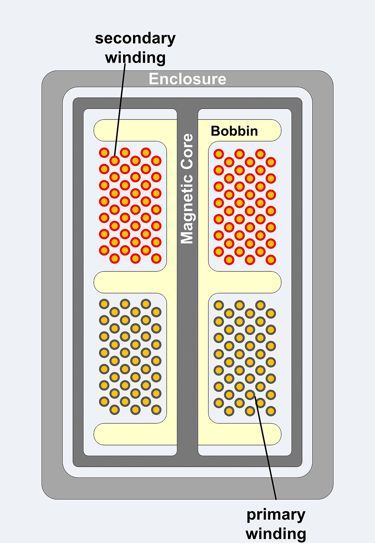
A particularly elegant construction is the split bobbin (or sectioned bobbin), in Figure 6, whose winding window is divided by one or more moulded partitions into separate chambers. The primary goes in one chamber and the secondary in another, and they never share a layer. The partition wall does two jobs at once: it provides a large, guaranteed creepage path between primary and secondary — the surface path now has to climb the full height of the wall and back down — and it removes the need for much of the margin and barrier tape, because the bobbin itself is the barrier. Split bobbins are common on small, cheap, safe mains transformers precisely because they build the required isolation into the moulding, where it cannot be wound wrong. The trade is coupling: the two windings sit in separate chambers rather than concentric and interleaved, so a split-bobbin transformer generally has higher leakage inductance than a concentric one — fine for a 50/60 Hz supply, often unacceptable for a high-frequency switcher, which is one reason SMPS transformers favour concentric windings with TIW or tape rather than split bobbins.
Terminations come in two families. A pinned bobbin has metal pins moulded into a base flange; the winder anchors and solders each lead to a pin, and the finished part drops into a PCB like any other component. A leaded bobbin brings flying wire leads out instead, for chassis or flying-lead wiring. Pinned bobbins make the creepage problem explicit: the pins themselves on the primary and secondary sides must be spaced to meet the creepage and clearance figures, which is why isolation-transformer bobbins put the primary pins on one end and the secondary pins on the other, as far apart as the moulding allows.
Toroids have no bobbin at all, and this changes the insulation picture. A toroidal transformer is wound directly onto the ring core, so the “system” is the core’s own insulating coating (an epoxy or tape wrap over the steel), the enamel on the wire, and tape barriers wound on by hand between the primary and secondary. There are no flanges, no margins in the bobbin sense, and no partition — so the winder must build the entire creepage and layer count out of tape and wire, wrapping insulating tape fully around the toroid between the primary and the secondary and taking care that the lead-out points on the two windings are kept far apart around the ring. Toroids reward this care with superb coupling and low leakage and a small external field, which is why they dominate high-quality audio and low-noise power supplies; but they demand that the winder understand the insulation system in its rawest form, because nothing in the mechanical design builds it in for them.
5.7 Bringing out the leads
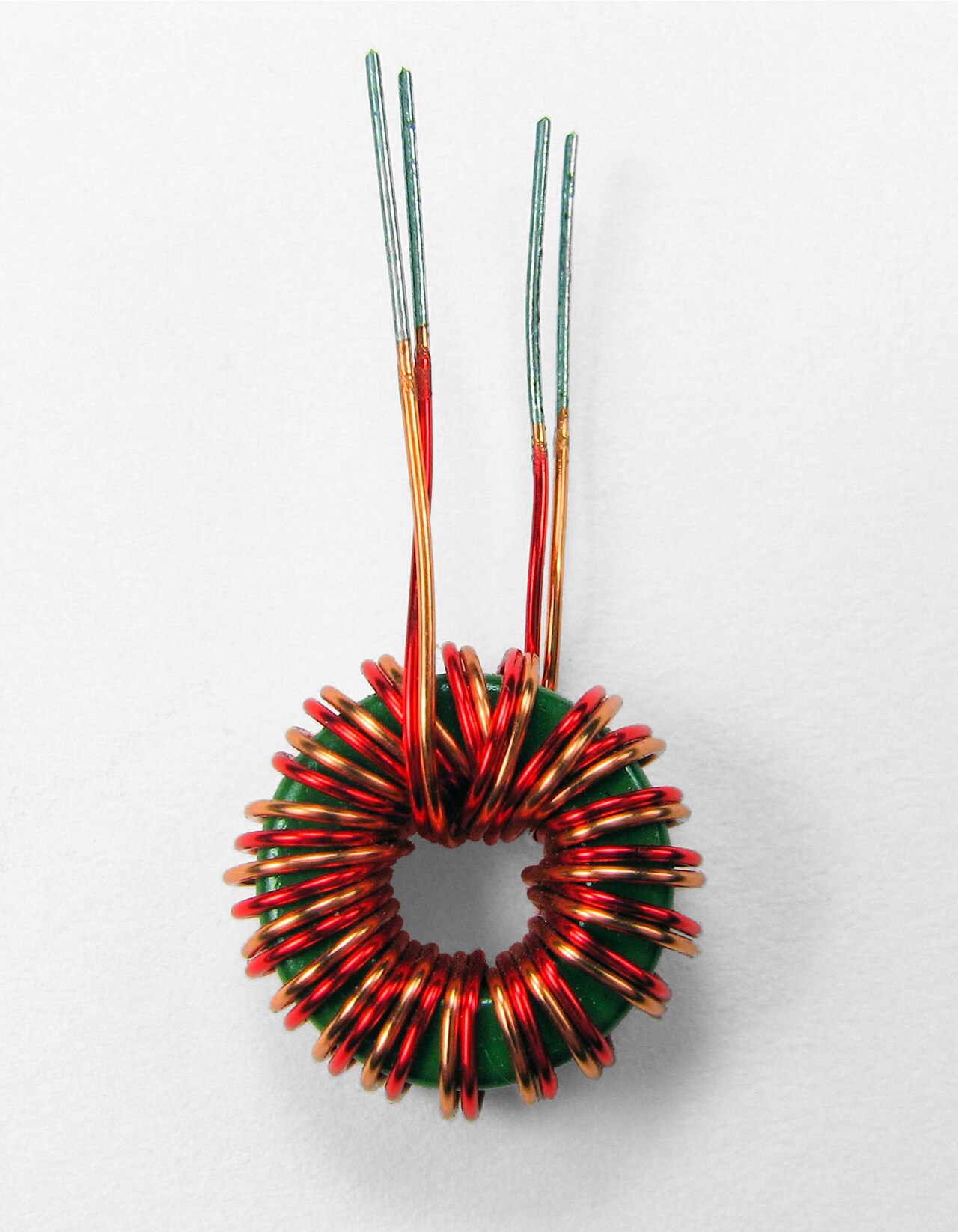
The last physical step is getting the winding’s ends out to the world without undoing the isolation the winder just built. Each lead is vulnerable at exactly the place it leaves the winding, where a fine enamelled wire has to survive handling, soldering, and strain. The standard measures are: slip an insulating sleeve over the emerging wire — PVC for ordinary work, PTFE or silicone or fibreglass sleeving where the temperature or voltage demands it — sized so the sleeving reaches from inside the winding out past the exit point, so that no bare or single-enamelled primary wire is exposed near a secondary lead. Tin the very end of a solderable lead in the solder pot (which also confirms the enamel actually cleared), or scrape and tin a non-solderable grade. Provide strain relief so that a pull on the external lead lands on an anchor — a pin, a tie, a dab of the impregnating varnish — and not on the delicate point where the fine wire joins the winding. And on a pinned bobbin, wrap the lead around its pin before soldering so the joint is mechanical first and electrical second. On safety-critical primaries the sleeving itself is often a rated part of the insulation system and is specified, not improvised. Sloppy lead-out is a common failure mode: a primary lead that chafes against a secondary pin, or a strain that eventually cracks the enamel at the winding exit, defeats an otherwise perfect barrier.
5.8 How wire and insulation set up the rest of the dive
Every choice in this volume feeds forward into the ones that build and test the transformer. The gauge and build picked here fix the copper loss and the fill factor that the design volume balances against temperature rise (Volume 9). The thermal class of the wire, tape, and bobbin sets the temperature the whole design is allowed to reach. The winding order, interleaving, and shielding decided here become the leakage inductance, capacitance, and noise behaviour the equivalent circuit (Volume 2) and the RF and switch-mode types (Volume 8) have to live with. The insulation system — enamel, interlayer, bobbin, margins or TIW — is the thing the winding-technique volumes (Volumes 10 to 12) physically lay down turn by turn, and the thing the hi-pot test (Volume 13) finally proves. And running underneath all of it is the one theme that separates a transformer from a coil and that no amount of clever winding can be allowed to compromise: on a mains transformer, the insulation is the safety, and the winder who respects the system — the classes, the creepage, the margins, the shield, the hi-pot — builds a part that is safe for the life of the equipment. The rest of this dive shows how to lay that copper down; this volume is why it has to be laid down right.
Comments (0)