Transformers and Transformer Winding · Volume 12
Build Your Own: Worked Projects
12.1 From method and machine to a finished part
The two volumes before this one supplied everything a builder needs on paper. Volume 9, the design engine, turned a specification into a turns count, a pair of wire gauges, and a core part number by way of the EMF equation 4.44 · f · N · Bmax · Ac. Volume 11, the technique, showed how to prepare a bobbin, wind a primary in even layers, lay an insulation barrier, bring out taps and leads, stack and interleave the laminations, and finish the coil with varnish and a hi-pot test. This volume closes the loop by walking six concrete builds from bare core to bench-tested device. Each one states its goal and specification, chooses a core and wire and turns count, lays out the winding steps (leaning on Volume 11 rather than repeating it), and says how the finished part is tested (leaning on Volume 13) and what to do when it misbehaves.
The projects are deliberately varied, because the transformer family is varied and each member teaches something the others do not. A mains power transformer rewind teaches diagnosis, the volts-per-turn trick, wire matching, and the non-negotiable safety of the insulation barrier. A toroidal power transformer teaches winding a closed ring, where there is no bobbin and no lamination stack to hide behind. A single-ended audio output transformer teaches the air gap and the interleaving that a DC-biased, wide-band device demands. A 1:1 isolation transformer teaches the safety build in its purest form, including an electrostatic shield. A current-sense transformer teaches the inverted world of the instrument transformer, where the primary is a single pass of a wire and the secondary must never be left open. And a 4:1 antenna balun, with a note on the 9:1 unun, teaches the transmission-line transformer, where the ferrite chokes rather than couples and the ratio comes from how the windings are connected. A builder who has done all six has met almost every winding problem the craft presents.
A word on safety runs through the whole volume and is stated once here so it need not be repeated at every step: any transformer with a winding that touches the mains is a life-safety device, and the barrier between its primary and any secondary a person can touch is what stands between the user and electrocution. That barrier is only as good as the insulation system that builds it and the hi-pot (high-potential) test that proves it, and no mains transformer described here goes near a socket until it has passed that test. The instrument-transformer project carries its own distinct hazard — a dangerous open- secondary voltage — and it is flagged where it arises.
12.2 Project 1 — Rewinding a small mains power transformer
12.2.1 The goal and the diagnosis
The first project is a repair rather than a from-scratch build, because repair is where most builders first open a transformer and because it forces the single most useful trick in the craft. The subject is a small mains transformer from a piece of linear-supply equipment — say a 48 VA unit stepping 230 V down to 12 V at 4 A — that has stopped working. The goal is to diagnose the fault, and if it is a failed secondary, to rewind that winding correctly and safely.
Diagnosis comes first and is the subject of Volume 13 in full; here it is enough to run the short checklist. With the transformer disconnected, a low-voltage resistance check across each winding separates the three common failures. An open winding reads infinite resistance where a few ohms are expected — a broken wire or a failed thermal fuse buried under the outer wrap. A shorted turn is subtler: the winding still reads low resistance, but under power the transformer draws heavy magnetizing current, buzzes, and heats fast, because the shorted turn acts like a one-turn secondary into a dead short. An insulation breakdown shows as continuity, or a low megohm reading, between windings that should be isolated — the most dangerous fault of all, because it can put mains onto the low-voltage side. A builder confirms which winding failed, and whether the core and the surviving winding are sound, before deciding to rewind.
For the worked example, assume the primary tests good (a few tens of ohms, well isolated) and the 12 V secondary reads open — a broken secondary, the commonest repairable fault. The plan is to strip only the secondary, leave the good primary undisturbed, and rewind the secondary to the correct turns.
12.2.2 The volts-per-turn test
Here is the trick that makes the whole repair possible without any of the original paperwork. The number that governs every winding on a given core is its volts-per-turn — the voltage a single turn develops when the core is fluxed by the primary. It follows directly from the EMF equation of Volume 9: volts-per-turn equals 4.44 · f · Bmax · Ac, a property of the core and the applied frequency, identical for the primary and every secondary. If a builder knows the volts-per-turn, the turns for any voltage are just that voltage divided by it.
The elegant way to measure volts-per-turn on a transformer whose primary is intact is to add a small temporary test winding and read what it produces. The builder winds ten turns of any thin scrap wire through the window, over the outside of the coil, brings the two ends out to a voltmeter, and — with the primary safely connected to the mains through a fused lead and, ideally, a current-limiting series lamp or a variac brought up slowly — measures the voltage across the ten turns. Ten turns is a good count: enough to give a readable few volts, few enough to add in a minute. Suppose the meter reads 6.9 V across the ten-turn winding.
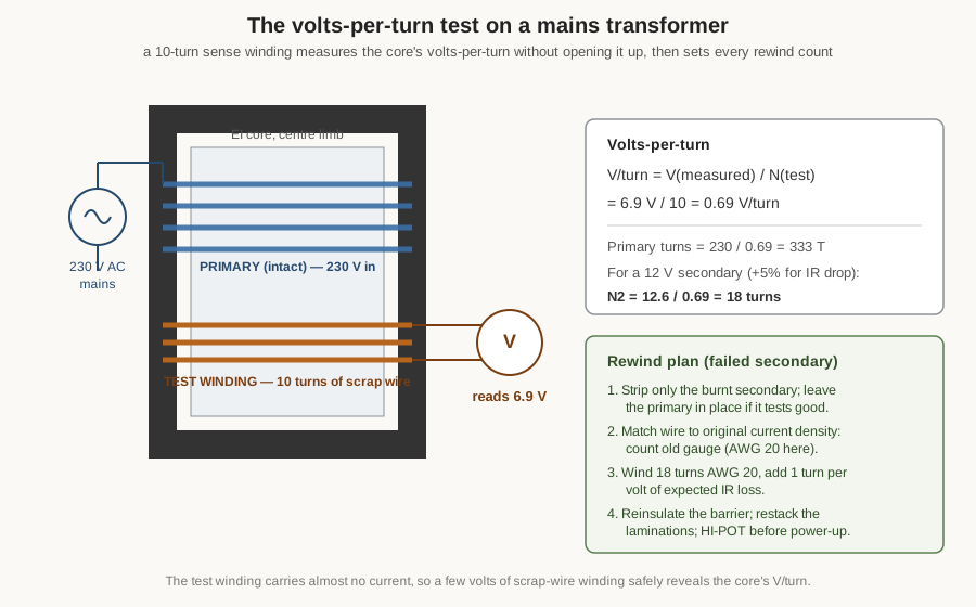
The arithmetic is immediate. Volts-per-turn is 6.9 V divided by 10 turns, or 0.69 V per turn. As a sanity check, the primary turns must be about 230 V divided by 0.69, near 333 turns — a believable number for a small mains transformer, and one a builder can verify by counting if the primary is ever unwound. To rewind the 12 V secondary, the turns needed are 12 V divided by 0.69, or roughly 17.4 turns; the count is rounded up and a small allowance added for the resistive voltage drop under load, because the 12 V is the wanted voltage at 4 A, not at no load. A secondary of a low-voltage, moderate-current transformer typically drops several percent from no load to full load, so adding perhaps one turn — winding 18 or 19 turns rather than 17 — lands the loaded output on target. The test winding is then removed; it has done its one job.
12.2.3 Matching the wire, rewinding, and the mandatory hi-pot
The replacement wire is matched to the original by two properties: gauge and insulation class. Gauge is set by the current the winding must carry at a safe current density — for a 4 A secondary at the usual 3 A per square millimetre or so, that is roughly AWG 20, and a builder confirms it by measuring the diameter of a strand of the old winding with a micrometer before discarding it. Using thinner wire to fit an awkward window is a false economy that ends in an overheating winding; using the original gauge is the safe default. The insulation class of the magnet wire and the interlayer and inter-winding insulation must match or exceed the original, because on a mains transformer that insulation is the safety barrier of Volume 5.
The rewind itself follows Volume 11’s technique. The failed secondary is unwound and its turns and layer structure noted; the exposed surface is inspected and any nicked interlayer insulation over the primary is repaired. A fresh interwinding barrier of the correct insulating tape is laid, the new secondary of AWG 20 is wound on in the tidy layers the machine and hand deliver, with the margins at the bobbin ends preserved so creepage distance is maintained, and the leads are sleeved and anchored. The coil is re-varnished if the original was impregnated, and the EI laminations are restacked and interleaved exactly as they came apart so the core’s magnetic path and stacking factor are restored.
Then, before the transformer goes anywhere near a socket, comes the step that is not optional: the hi-pot test. A hi-pot (dielectric withstand) tester applies a high AC or DC voltage — for a mains transformer, commonly on the order of 1.5 kV to 3 kV — between primary and secondary for a timed interval, and watches for breakdown. Passing it proves the rewound barrier will hold off the mains under fault conditions; failing it condemns the rewind before it can hurt anyone. A builder who skips the hi-pot has built a device that may work perfectly for months and then, one day, put 230 V onto the 12 V rail. The test is cheap insurance against a lethal outcome, and Volume 13 describes the procedure and the limits in detail.
12.2.4 Troubleshooting the rewind
If the rewound secondary reads a volt or two low under load, the turns allowance for IR drop was too small; adding a turn or two corrects it. If the transformer runs warm at no load and hums, a lamination was left out or the stack is loose, raising the magnetizing current and the core loss — restacking tightly and adding the missing lamination cures it. If the hi-pot fails, the barrier is compromised somewhere; the winding comes apart again and the insulation is rebuilt, because there is no shortcut past a failed hi-pot.
12.3 Project 2 — Winding a toroidal power transformer
12.3.1 Goal, core, wire, and turns
The second project builds a small toroidal power transformer from scratch — say a 30 VA unit delivering 2 × 9 V for a dual-rail supply. The toroid is chosen because it is compact, quiet, and low in leakage, and because winding one teaches the technique that a bobbin hides: on a toroid there is no former and no lamination stack, only a closed ring that the wire must be threaded through, turn by turn, all the way round.
The core is a suitable grain-oriented-steel or iron-powder toroid sized by the area-product method of Volume 9 for 30 VA at 50/60 Hz. Suppose the design gives a volts-per-turn of about 0.5 V — again from 4.44 · f · Bmax · Ac — so the 230 V primary needs about 460 turns and each 9 V secondary about 20 turns (with the usual loaded-output allowance). The primary is wound in a fine gauge that fits 460 turns around the window — perhaps AWG 30 for the low primary current — and each secondary in the gauge its current demands.
12.3.2 The winding steps
The steps follow Volume 11’s toroid section and Volume 10’s account of the shuttle winder. First the bare core is deburred and wrapped with insulating tape, because a toroid’s sharp edges will otherwise cut the first layer of enamel — the commonest cause of a primary-to- core short. The primary is then wound on. Because a closed ring cannot spin on a spindle, the wire is either pre-loaded onto a shuttle (a split C-shaped ring that passes through the core’s hole, paying one turn per pass) or, for a small core, threaded by hand turn by turn. Each turn is spread so the primary occupies the full 360 degrees of the ring evenly; bunching the winding into one arc wastes window and raises leakage, defeating the point of the toroid. The turns counter — or the builder’s tally — must land on exactly the design count, because the ratio is exact.
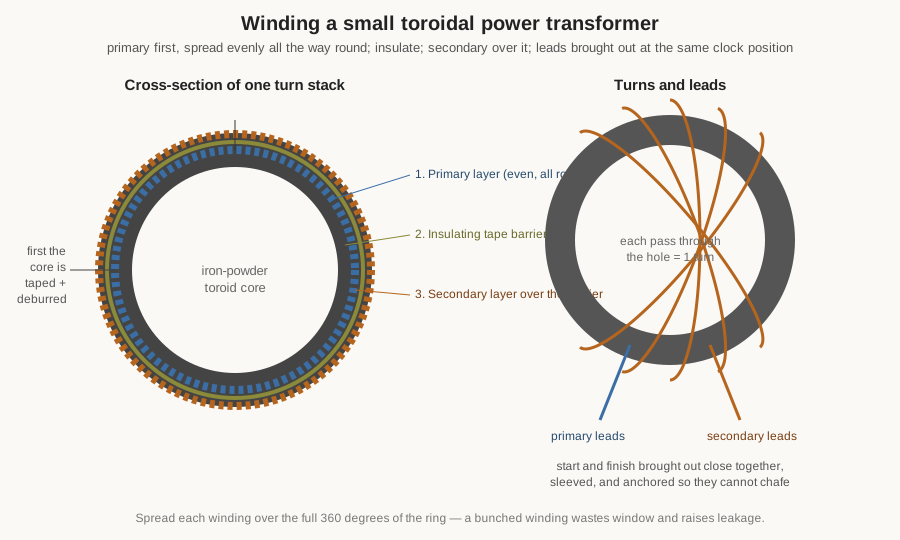
Over the finished primary the builder lays an insulating tape barrier, then winds each secondary over it — again spread evenly round the ring, again counted exactly. Bringing out the leads is its own small craft: the start and finish of each winding are brought out close together at one clock position, given a service loop, sleeved with insulating tubing, and anchored so they cannot chafe against the core’s edge under vibration. A final overwrap of tape, and — if the design calls for it — a dip in varnish and a bake, finish the part. Because it is a mains transformer, it too gets the hi-pot test of Project 1 before use.
12.3.3 Testing and troubleshooting
On the bench (Volume 13) the builder confirms the turns ratio by applying a low AC voltage to the primary and reading each secondary, checks the winding resistances, and measures the magnetizing current at rated voltage — a low, clean current if the core is good. If a secondary reads high or low, the turn count was off and a turn is added or removed. If the magnetizing current is high and the core buzzes, either the winding does not go all the way round (leaving part of the core poorly coupled) or the tape wrap left the core over-stressed; rewinding evenly cures it. A toroid that runs hot at light load usually has a nicked primary shorting a turn to the core — the reason the deburring and first tape wrap are not optional.
12.4 Project 3 — A single-ended tube audio output transformer
12.4.1 Goal and the two hard problems
The third project is the connoisseur’s build: a single-ended (SE) output transformer for a small tube amplifier, matching a 5 kΩ plate load to an 8 Ω loudspeaker. Its goal is not merely to transform an impedance but to do so across the whole audio band, 20 Hz to 20 kHz, while a steady DC plate current flows through the primary. Those two demands — wide bandwidth and DC in the primary — are what make an output transformer far harder than a power transformer, and they drive two features that a power transformer never needs.
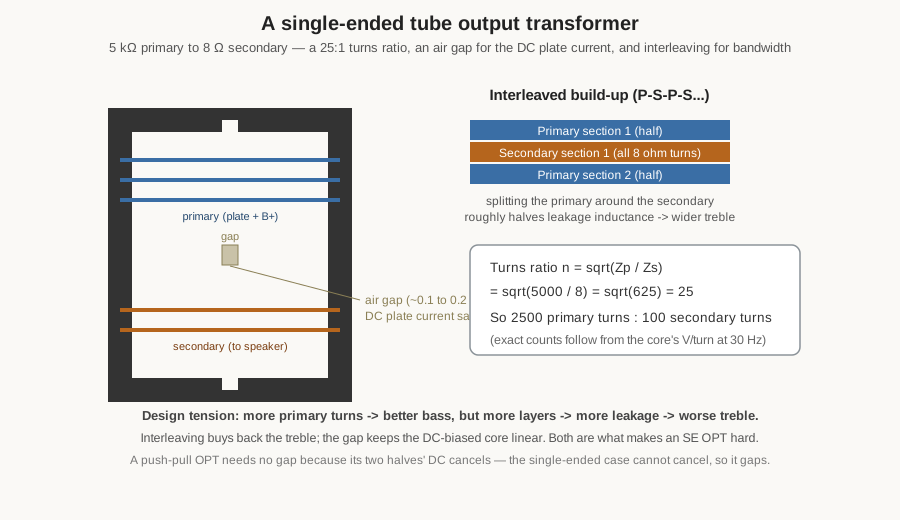
The impedance ratio fixes the turns ratio at once: the turns ratio n equals the square root of the impedance ratio, so n equals the square root of 5000 divided by 8, which is the square root of 625, or 25. The transformer is a 25:1 step-down — perhaps 2500 primary turns to 100 secondary turns, with the exact counts set by the core’s volts-per-turn at the lowest frequency of interest (bass, at 30 Hz or so, needs the most turns and the most core, which is why an SE OPT is large for its power).
12.4.2 The gap and the interleaving
The first special feature is the air gap. In single-ended operation the whole plate current — tens of milliamps of DC — flows one way through the primary, magnetising the core steadily toward saturation. A saturated core has collapsing inductance, which throttles the bass and adds gross distortion. The cure is a small air gap in the magnetic path — on the order of 0.1 to 0.2 mm, a slip of paper or plastic shim between the E and I laminations, which are stacked all-E-one-way rather than interleaved for exactly this reason. The gap stores the DC’s magnetomotive force in reluctance instead of steel, holding the core linear at the cost of some inductance and thus some low-frequency reach. (A push-pull output transformer needs no gap because its two primary halves carry opposing DC that cancels in the core — the single-ended topology has nothing to cancel against, so it must gap. This is the central reason SE and push-pull output transformers are built differently.)
The second special feature is interleaving for bandwidth. Treble reach is limited by leakage inductance — the flux that links one winding but not the other — which forms a low-pass filter with the load. The fix is to split the primary into sections and sandwich the secondary between them, so primary and secondary are physically interwoven rather than stacked one outside the other. A simple and effective scheme winds half the primary, then the entire secondary, then the other half of the primary; more ambitious transformers use many more sections. Each split roughly halves the leakage inductance and pushes the treble rolloff up, at the cost of more inter-winding capacitance and a fussier wind. The builder balances the two: enough interleaving for flat treble, not so much that capacitance rings.
12.4.3 Testing and troubleshooting
Bench testing (Volume 13) drives the primary from a signal generator through a resistor standing in for the tube’s plate resistance, loads the secondary with 8 Ω, and sweeps the frequency while watching the output — a flat response from tens of hertz to beyond 20 kHz is the goal. Weak, distorted bass means too few primary turns or too small a gap (the core is saturating); rolled-off treble means too much leakage and calls for more interleaving on the next wind. A resonant peak near the top of the band is the leakage inductance ringing with the winding capacitance and can be tamed with a small resistor-capacitor snubber across the primary. An SE OPT rewards patience: it is the one transformer where the winding order, not just the turns, sets the sound.
12.5 Project 4 — A 1:1 isolation transformer with a shield
12.5.1 Goal and why 1:1
The fourth project builds a 1:1 isolation transformer: 230 V in, 230 V out, but with the output winding galvanically separate from the input so that neither output terminal is tied to the mains neutral or earth. Its purpose is safety — it lets a technician work on a live chassis without the shock hazard of a direct connection to the grounded mains, and it protects sensitive equipment from ground loops. The turns ratio is 1:1, so primary and secondary have equal turns, and the design (Volume 9) sizes the core for the VA and the wire for the current exactly as for any power transformer. A 1:1 isolation transformer does not change the voltage; its entire value is in the barrier between the two windings.
12.5.2 The build and the electrostatic shield
Because the whole point is isolation, this build treats the inter-winding barrier with the most care of any in the volume. The primary and secondary are wound on separate sections of a split bobbin where possible, or with a heavy reinforced-insulation barrier between them on a common bobbin, so that creepage and clearance meet the reinforced-isolation requirements of Volume 5. The two windings never share a layer and their leads exit at opposite ends of the bobbin to keep the primary and secondary physically far apart.
The distinctive extra feature is the electrostatic shield — often called a Faraday shield or screen. This is a single layer of thin copper foil (or a single-layer winding of fine wire) laid between primary and secondary, its one end brought out and connected to earth, and — critically — the foil overlapped but not closed into a shorted turn, because a closed turn around the core would act as a shorted secondary and burn out. The shield intercepts the capacitive (electrostatic) coupling between primary and secondary, draining mains-frequency and high-frequency noise currents to earth instead of letting them pass through the transformer. In a safety isolation transformer the shield both reduces leakage current to the isolated side and improves noise rejection, and its earth connection is part of the safety design.
The finished isolation transformer, being a mains device with an even more critical barrier than most, gets a hi-pot test at the reinforced-insulation level and a leakage-current measurement (Volume 13) before it is trusted. Troubleshooting is mostly a matter of the barrier: excessive leakage current to the isolated side points to a shield that is missing, mis-earthed, or accidentally closed into a shorted turn; a hi-pot failure condemns the barrier as before.
12.6 Project 5 — A current-sense transformer (CT)
12.6.1 The inverted transformer
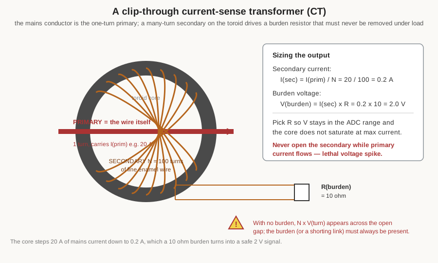
The fifth project is an instrument transformer, and it inverts almost everything the previous builds assumed. A current-sense transformer measures the current in a conductor without breaking into it: the conductor itself is the primary, threaded once through the hole of a small toroid, so the primary is a single turn. The secondary is a many-turn winding on the toroid — 100 turns is a convenient round number, though CTs run from tens to thousands of turns — and it delivers a scaled-down replica of the primary current. A burden resistor across the secondary converts that current into a measurable voltage. The goal for the worked example is to sense a 20 A mains load and produce a safe, low-voltage signal an analog-to-digital converter can read.
12.6.2 Core, turns, and the burden
The core is a small ferrite or nanocrystalline toroid; the secondary is 100 turns of fine enamel wire wound evenly around it (Volume 11’s toroid technique again, at small scale). Because the primary is one turn and the secondary is 100 turns, the CT is a 1:100 current step-down: a primary current of 20 A drives a secondary current of 20 divided by 100, or 0.2 A. That 0.2 A flows through the burden resistor, and the burden sets the output voltage by Ohm’s law: with a 10 Ω burden, the output is 0.2 A × 10 Ω, or 2.0 V at full 20 A load — a clean signal for a microcontroller’s ADC. The burden is chosen so the full-scale voltage suits the measuring circuit and so the core does not saturate at the maximum primary current; a smaller burden gives a smaller, safer voltage but less resolution, and the builder trades the two.
12.6.3 The open-secondary hazard
The CT carries a hazard unique among these builds and it must be stated plainly. The loaded secondary of a current transformer must never be left open. With the burden in place, the secondary voltage is small (2 V in the example). Remove the burden while primary current still flows, and the core is no longer held near zero flux by the secondary ampere-turns; it drives hard toward saturation, and the collapsing flux induces a very high voltage — potentially hundreds or thousands of volts — across the open secondary terminals, enough to break down the winding insulation and to injure or kill. The rule, carried over from the instrument-transformer treatment of Volume 8, is absolute: before disconnecting a CT’s burden or meter, the secondary is first shorted with a shorting link or switch. A permanently fitted burden resistor, soldered across the secondary, is the safest practice for a home build precisely because it can never be accidentally removed.
Testing (Volume 13) drives a known primary current through the single turn and checks that the burden voltage tracks it linearly up to full scale, where core saturation eventually flattens the response. A CT that reads low across the board has too few secondary turns or too small a burden; one that goes nonlinear early is saturating and needs a larger core or a smaller burden.
12.7 Project 6 — A 4:1 antenna balun (and the 9:1 unun)
12.7.1 Goal and the transmission-line idea
The sixth project is the ham-radio classic: a 4:1 balun for feeding a balanced antenna from unbalanced 50 Ω coax across the HF bands. A balun (balanced-to-unbalanced) matches an unbalanced feed line to a balanced load and chokes the common-mode current that would otherwise flow on the outside of the coax; a unun (unbalanced-to-unbalanced) does the impedance step between two unbalanced circuits. The 4:1 balun steps 50 Ω up to 200 Ω, a common match for folded dipoles and some loop and off-centre-fed antennas.
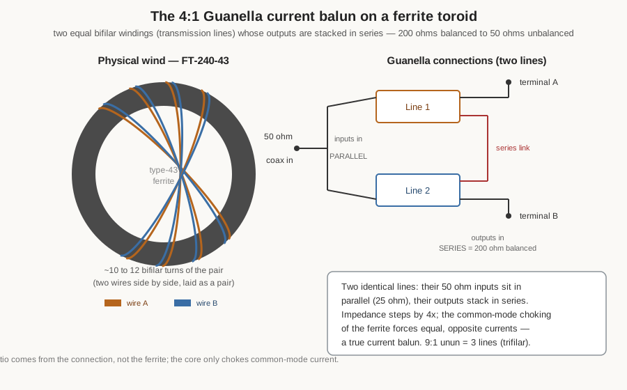
What makes this build different from every other in the volume is that it is a transmission-line transformer. The wire is not wound to couple flux from a primary to a secondary in the ordinary way; it is wound as a pair of transmission lines whose electrical action does the transforming, while the ferrite core’s job is only to present a high impedance to common-mode current — to choke it — across the band. The ratio comes from how the two lines are connected, not from a turns count in the flux-coupling sense. This is why a broadband HF balun works over a 30:1 frequency range that no ordinary flux-coupled transformer could span.
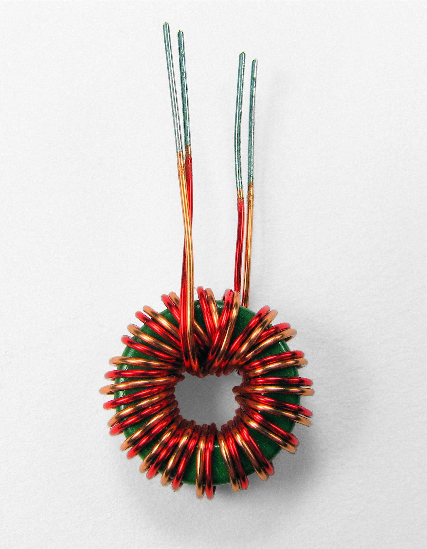
12.7.2 Core, wire, turns, and the Guanella connection
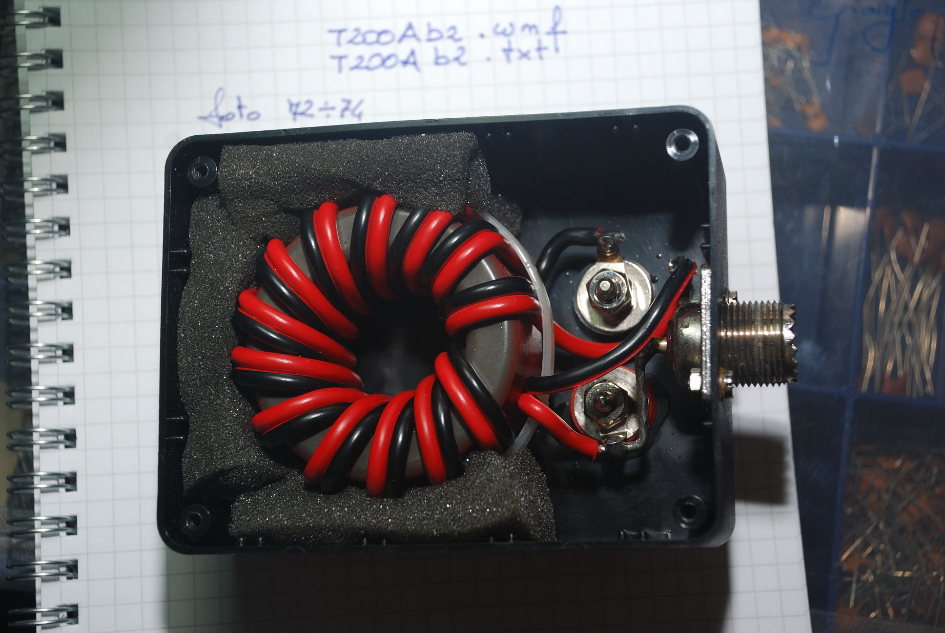
The core is a ferrite toroid of a mix suited to HF — the classic choice is an FT-240-43 (a 2.4-inch type-43 ferrite ring) for a 100 W-class balun, with the smaller FT-140-43 used for lower power or higher bands. The Guanella 4:1 current balun is built from two equal bifilar windings — two wires laid side by side and wound together as a pair, forming a transmission line — of about 10 to 12 turns each on the toroid. (The 13-turn build shown in the photograph is a typical example; the exact turn count is chosen so the winding’s common-mode impedance is high across the lowest band of interest, usually a few hundred ohms or more.) The two lines’ inputs are wired in parallel and their outputs are stacked in series: paralleling two 50 Ω line inputs gives 25 Ω, the series outputs give 200 Ω, and the 4:1 impedance step falls out of the connection. The ferrite’s choking action forces equal and opposite currents in the two conductors, which is what makes it a current balun — the kind that actually suppresses common-mode current and keeps RF off the coax shield.
A related build is worth naming because it shares the method. The 9:1 unun, the standard matchbox for an end-fed random-wire antenna, steps a high antenna impedance down toward 50 Ω and is wound as a trifilar winding — three wires laid together — of about 9 turns on the same FT-240-43 core. Its three windings are connected in the sequence that stacks them 3:1 in voltage (and so 9:1 in impedance): the end of the first joins the start of the second, the end of the second joins the start of the third, and the taps are brought out at the junctions. It is the same transmission-line idea as the 4:1 balun, with three lines instead of two and a different connection.
12.7.3 Testing and troubleshooting
The balun is tested (Volume 13) with an antenna analyser or a vector network analyser: terminated in a 200 Ω non-inductive load, it should present close to 50 Ω with a low standing-wave ratio across the intended bands, and the common-mode choking impedance should stay high at the low end. A balun that shows a rising SWR at the high-frequency end usually has too many turns (excess winding capacitance) or leads too long; one that fails to choke common-mode at the low-frequency end has too few turns or the wrong ferrite mix. Overheating under power points to a core mix with too much loss for the frequency, or to operating a small core beyond its power rating — the ferrite, not the copper, is usually the limit in a balun. The transmission-line transformer rewards a short, tidy, symmetrical wind and a core mix matched to the band.
12.8 Troubleshooting transformers in general
The projects above each carried their own failure notes, but a builder benefits from a single map of the symptoms that recur across all transformer types, their usual causes, and the fixes. Most transformer faults announce themselves as one of a handful of symptoms — overheating, hum or buzz, low or wrong output, or an outright short — and each symptom points to a small set of causes. The table below collects them; the prose that follows draws out the ones that trip up builders most often.
Overheating is the most common complaint and has three main roots. A transformer that runs hot at no load is losing power in the core: too few primary turns, too high a supply voltage, or a loose or gappy lamination stack raises the flux density and the magnetizing current, and the iron heats. A transformer that runs hot only under load is losing power in the copper: undersized wire, too many turns crammed into the window, or simply drawing more current than it was designed for. And a transformer that heats fast and hums hard almost always has a shorted turn, which behaves like a one-turn secondary into a dead short and dumps large circulating current into the winding — often from insulation nicked during winding, the reason the deburring and clean layering of Volume 11 matter.
Hum and buzz divide into electrical and mechanical. A steady mechanical buzz is loose laminations vibrating at twice the line frequency (magnetostriction), cured by tightening the clamp and impregnating the core with varnish. An electrical hum injected into a following circuit is usually capacitive or magnetic coupling, addressed by the electrostatic shield of Project 4 or by reorienting the transformer. Low output is most often a turns-count error, a winding drop under load larger than allowed for, or — if it worsens with load — a partially shorted winding. Wrong phase (an output that opposes another winding when they should add) is a leads-reversed error, corrected by swapping the winding’s two leads and confirming with the polarity test of Volume 13.
Table 1 — Troubleshooting transformers in general
| Symptom | Likely cause | Fix |
|---|---|---|
| Hot at no load, low hum | Too few primary turns / over-voltage / loose lamination stack raising flux | Restack tight, add missing laminations, confirm turns and supply voltage |
| Hot only under load | Undersized wire, over-stuffed window, or overload | Rewind in correct gauge; reduce load to rating |
| Hot fast, hard hum, high magnetizing current | Shorted turn (nicked enamel, insulation failure) | Rewind the affected winding; deburr and insulate the core |
| Mechanical buzz at 2x line frequency | Loose laminations / poor impregnation | Tighten clamp; varnish-impregnate and bake |
| Low or drooping output | Turns error, IR drop under-allowed, or partial short | Add turns; verify count; check for shorted turn |
| No output, open winding | Broken wire or blown thermal fuse | Locate break/fuse; rewind or replace |
| Output opposes another winding | Reversed leads / wrong phasing | Swap the winding leads; confirm with polarity test |
| Continuity primary-to-secondary | Insulation breakdown (dangerous) | Scrap or fully rewind the barrier; hi-pot before use |
| Balun: high SWR at HF end | Too many turns / long leads / winding capacitance | Reduce turns; shorten and symmetrise leads |
| CT reads low or nonlinear early | Too few secondary turns / burden too small / core saturating | Add turns; resize burden; use a larger core |
The single most important entry in that table is the one about continuity between primary and secondary, because it is the only fault that is a danger to life rather than merely to the equipment. A transformer that shows any leakage path between its mains side and a touchable secondary is condemned until the barrier is rebuilt and hi-pot tested. Every other fault costs a rewind; that one can cost a life.
12.9 The finale — where the whole program has led
This volume is the last hands-on chapter of the transformer dive and the finale of the whole passive-components program, so it is worth naming the threads it ties together. Every project here reached back to the two volumes before it: the turns counts came from the design engine of Volume 9 — the EMF equation solved for N, the area-product core selection, the wire sizing by current density — and the winding, insulating, tapping, stacking, and finishing steps came from the technique of Volume 11. Each project handed forward to Volume 13, where the finished part is measured and proven: the turns ratio and winding resistance, the magnetizing and leakage inductance, the open- and short-circuit tests that recover the very core and copper losses the design estimated, the polarity check, and — for every mains build — the hi-pot that proves the safety barrier. And the constants, equations, and tables that ran through all of it are collected in the reference of Volume 14.
Beyond this dive, the projects lean on the companion volumes of the wider program. The core-material choices — grain-oriented steel for the mains and audio builds, ferrite mixes for the balun and CT — come from Volume 4 and from the Coils and coil winding dive, which treats the same cores from the single-winding side. The magnet wire, the insulation classes, and the creepage-and-clearance safety came from Volume 5. The winding machines that lay these windings evenly and count them exactly are the subject of Volume 10 and of the Coils dive’s machine volume, and they are, in the builder’s own shop, the CNC coil winders documented under the Model Shop’s Coil Winders pages — the same machines that wind a choke will wind a transformer’s primary, a balun’s bifilar pair, or a CT’s hundred- turn secondary. And the broader passive-components program — the Capacitors and Resistors dives — supplies the burden resistors, the snubber components, and the filter capacitors that surround every transformer in a real circuit.
A transformer that seemed, at the start of this dive, like an almost magical black box is now, at the end of it, an object a builder can diagnose, design, wind, and prove on the bench. The six projects here are not an exhaustive catalogue — no six could be — but between them they exercise every core skill the craft demands: the volts-per-turn diagnosis, the even toroid wind, the gapped-and-interleaved audio build, the shielded safety barrier, the inverted instrument transformer, and the transmission-line balun. A builder who has wound all six has the hands and the judgement to take on the seventh, whatever it turns out to be. That is where the program leaves the reader: not with a device to admire, but with a bench, a machine, a spool of wire, and the knowledge to turn a specification into a transformer of their own.
Comments (0)