Transformers and Transformer Winding · Volume 13
Measuring and Testing Transformers
13.1 From the winding bench to the test bench
Every volume up to this one has been about putting a transformer into the world — the physics that make it work, the equivalent circuit that describes its imperfections, the core and wire it is built from, the machines that wind it, and the hands-on craft of laying the turns. This volume turns the whole dive around and asks the opposite question: given a finished transformer sitting on the bench — one that has just come off the winder, or one salvaged from a chassis with no markings, or one that is misbehaving in a circuit — how does the builder find out what it actually is? What is its turns ratio? Where are its losses? Is its insulation safe to energize? Will it hold its output voltage under load, and how hot will it run?
The answer is a small, well-established toolkit of bench tests, most of them a century old and still standard practice in transformer manufacture, that together measure every parameter the earlier volumes defined. The turns-ratio test recovers the n of Volume 1. The winding-resistance, magnetizing-inductance, and leakage-inductance measurements fill in the individual elements of the equivalent circuit of Volume 2. The open-circuit and short-circuit tests — the two classic power tests — split the transformer’s total loss cleanly into core loss and copper loss and hand back the complete equivalent circuit without the tester ever having to load the transformer to its rated power. The polarity test finds the dots when the winding is unmarked. And the insulation-resistance and hi-pot tests — the safety tests — prove that a mains transformer’s isolation barrier will actually hold off the line voltage before anyone plugs it in, which for a home-wound mains part is not optional but the single most important measurement in this volume.
The reader who has followed the design volume (Volume 9) will recognise this as the other half of a loop. Design predicts the losses, the regulation, and the temperature rise from the core geometry and the turns count; testing measures them on the finished article and tells the builder whether the prediction came true. A transformer that tested out on the bench exactly as the design sheet said it would is the reward for getting the volts-per-turn, the wire gauge, and the interleaving right — and a transformer that disagrees with its design sheet is pointing at a fault the tests are about to localise.
Two habits run through everything that follows. The first is that a transformer is a low-impedance AC device, and most of these tests energise a winding, so the safety discipline of Volumes 5 and 11 applies at the bench as much as at the winder: a mains primary under test sits at lethal potential, and the hi-pot test deliberately applies several kilovolts. The second is that the tests are cumulative and complementary — no single measurement characterises a transformer, but the seven or eight in this volume, run in sequence, leave nothing important unknown.
13.2 Turns ratio: the first and simplest measurement
The turns ratio is the transformer’s defining number — the n = N₁/N₂ that Volume 1 built the whole idea of the device around — and it is also the easiest thing to measure, because the transformer measures it for the tester. Apply a known AC voltage to one winding and the other winding reports the ratio directly as a voltage: by the ideal relation V₁/V₂ = N₁/N₂, reading both voltages and dividing gives the turns ratio without ever counting a turn.
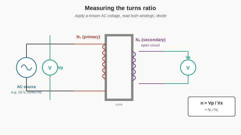
The practical method uses a small, safe excitation rather than the rated voltage. A signal generator or a low-voltage AC supply — a few volts up to perhaps ten, at line frequency — is connected across one winding, and a pair of true-RMS voltmeters (or one meter moved between the windings) reads the applied voltage and the induced voltage. The secondary is left open so that no load current flows and the tiny magnetizing current does not drop any appreciable voltage across the winding resistance; under those conditions the measured voltage ratio is the turns ratio to within a fraction of a percent. For a step-down mains transformer it is usually cleaner to excite the high-voltage winding, because exciting the low-voltage winding and reading a stepped-up open-circuit voltage on the high side can put a surprising and hazardous voltage on the meter — driving 10 V into a 24 V secondary of a 240 V transformer produces about 100 V on the primary terminals.
A dedicated instrument does this to laboratory accuracy: the transformer turns-ratio (TTR) tester, a staple of power-transformer maintenance. A TTR applies a stable reference voltage, measures the ratio (and, in modern bridge-type instruments, the phase angle and excitation current at the same time), and reads the ratio out to four or five significant figures. On a multi-tap winding the TTR is stepped through each tap in turn, and the measured ratios are compared against the nameplate. This is exactly how a mis-tapped or shorted-turn winding is caught: a ratio that reads high or low by one or two turns’ worth means the tap lead was brought out on the wrong turn during winding, and a ratio that is close but comes with an abnormally high excitation current is the classic signature of a shorted turn — the shorted turn acts as a loaded single-turn secondary, drawing heavy circulating current and dragging the ratio slightly off. For the home winder without a TTR, the two-voltmeter method catches the same gross errors: wind the tap one turn wrong on a 20-turn-per-volt design and the tapped voltage lands a full volt off, which the voltmeter reads plainly.
13.3 Winding resistance: the DC picture of the copper
Where the turns-ratio test looks at the transformer as an AC device, the winding-resistance test looks at each winding as a plain length of copper wire and measures its DC resistance (DCR). This is the same four-wire, or Kelvin, measurement described at length in the Resistors dive (Volume 13 of that companion series): a milliohm-meter or DLRO forces a known DC current through the winding on one pair of leads and senses the voltage drop on a separate pair right at the winding terminals, so that the resistance of the test leads and their contacts is excluded and only the copper itself is measured. A two-wire ohmmeter cannot do this — its own lead and contact resistance, a few tens of milliohms, swamps the sub-ohm resistance of a heavy low-voltage winding.
The DCR is worth measuring for three reasons. First, it is a direct check on the wire and the turns: for a known wire gauge and a known mean-length-per-turn, the resistance follows from R = ρ·l/A, so a winding that reads far higher than calculated was wound with thinner wire than intended or has more turns than intended, and one that reads far lower has fewer turns or heavier wire. Second, an open winding reads infinite — the obvious diagnosis of a broken lead or a burnt-out winding — and a shorted winding, or one with shorted turns, reads abnormally low. Third, and most usefully, the DCR feeds the two most quantitative tests in this volume: it is the copper resistance that appears in the equivalent circuit’s R₁ and R₂, and it is the quantity whose change with temperature underlies the temperature-rise test at the end of this volume. Because a transformer must settle to a stable temperature before its DCR is meaningful — copper’s resistance rises about 0.4% per °C — the winding is left un-energised long enough to reach ambient, and the ambient temperature is recorded alongside the reading.
13.4 Magnetizing and leakage inductance: the two faces of the LCR meter
The equivalent circuit of Volume 2 contains two very different inductances, and both are measured on an ordinary LCR meter using the same winding — the only thing that changes between the two measurements is what the other winding is doing. This is one of the most useful and least appreciated pairs of measurements on the bench, because the two numbers govern completely different aspects of the transformer’s behaviour.
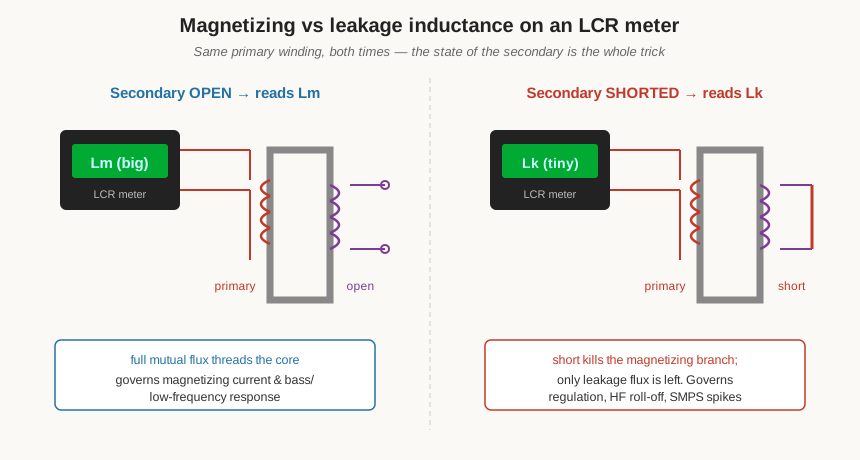
To measure the magnetizing inductance Lₘ, the LCR meter is connected across one winding and the other winding is left open. In that state the meter sees the full inductance of the winding on its core: the mutual flux threads the whole magnetic circuit, and the reading is large — henries for a mains transformer’s primary, because the core’s high permeability multiplies the inductance enormously. This is the inductance of the magnetizing branch, Lₘ = Xₘ/(2πf), and it is what sets the magnetizing current the transformer draws at no load and, in an audio or signal transformer, the low-frequency corner: the primary inductance and the source impedance form a high-pass filter, so a transformer with too little Lₘ loses bass. Because the core is nonlinear, Lₘ is not a single number — it depends on the flux density, hence on the test voltage and frequency — so a meaningful magnetizing-inductance figure is quoted with the excitation level at which it was taken, and a serious measurement drives the winding near its working flux rather than at the LCR meter’s tiny default test level.
To measure the leakage inductance Lₖ, the meter stays on the same winding but the other winding is now shorted. The short is the trick: it forces the mutual flux to nearly zero — the shorted secondary’s ampere-turns oppose and cancel the primary’s, exactly the ampere-turn balance of Volume 6 — so the magnetizing branch effectively vanishes and the only inductance the meter can see is the leakage, the flux that links one winding but not the other and never couples across. This reading is small — microhenries to a few millihenries — and it is the leakage inductance that dominates a transformer’s regulation (the series reactance that drops voltage under load), its high-frequency roll-off (the leakage reactance rises with frequency until it chokes off the output), and, in a switch-mode transformer, the voltage spike at turn-off, because the energy stored in the leakage inductance has nowhere to go when the switch opens and rings up against the circuit’s capacitance. Measuring Lₖ from each side and comparing tells the winder how tightly the primary and secondary are coupled: a well-interleaved winding shows low leakage, and a leakage that comes out higher than expected points straight back to poor interleaving or too much separation between primary and secondary — the very technique Volume 11 spent its length on.
13.5 The open-circuit test: finding the core loss
The two power tests — open-circuit and short-circuit — are the classic pair that between them build the entire equivalent circuit and predict the transformer’s efficiency and regulation, and they do it without ever loading the transformer to its full rated power. Their cleverness lies in separating the losses: the open-circuit test isolates the core loss, the short-circuit test isolates the copper loss, and because those two loss mechanisms respond oppositely to the two test conditions, each test sees essentially one loss and not the other.
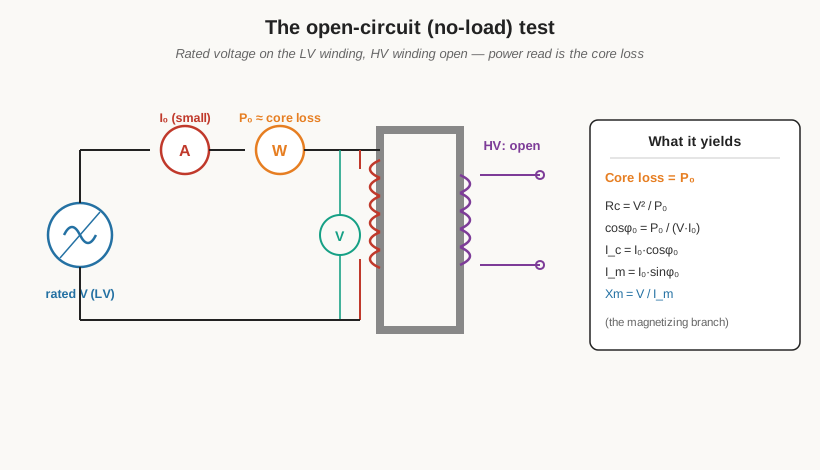
In the open-circuit (or no-load) test, one winding is energised at its rated voltage while the other winding is left open, and three instruments read the applied voltage, the current drawn, and the power consumed. Because the secondary is open, no load current flows; the only current the source delivers is the small exciting current I₀, typically a few percent of the winding’s rated current. That current is small enough that the copper loss it causes (which goes as the square of the current) is utterly negligible — a few percent of rated current squared is a few ten-thousandths of the rated copper loss — so essentially all the power the wattmeter reads is being burned in the core: the hysteresis and eddy-current losses of Volume 2 and Volume 4. The open-circuit power P₀ is therefore the core loss, at rated flux, full stop.
For convenience the open-circuit test is almost always run from the low-voltage side, because it is far easier and safer to source a modest rated LV voltage than to raise the full rated HV voltage, and the open HV terminals then sit at their rated (high) voltage but draw no current. The measurement also hands back the magnetizing branch. The applied voltage V and the core-loss power P₀ give the core-loss resistance directly, Rc = V²/P₀. The exciting current is then resolved into two components using the measured power factor, cos φ₀ = P₀/(V·I₀): the in-phase part Ic = I₀·cos φ₀ is the current that feeds the core loss, and the quadrature part Iₘ = I₀·sin φ₀ is the magnetizing current, from which the magnetizing reactance follows as Xₘ = V/Iₘ. Those two elements, Rc and Xₘ, are the shunt (magnetizing) branch of the equivalent circuit, measured rather than estimated. One practical note the open-circuit test makes vivid: the exciting current is markedly non-sinusoidal, peaked by the core’s saturation curve, so a true-RMS meter is needed to read I₀ honestly, and a real wattmeter (not a volts-times-amps guess) is needed for P₀ because the power factor at no load is very low.
13.6 The short-circuit test: finding the copper loss
The short-circuit (or impedance) test is the open-circuit test’s mirror image. One winding is deliberately shorted with a heavy link, and a reduced voltage — only a few percent of rated, just enough to push rated current through the windings — is applied to the other. Again three instruments read the applied voltage, the current, and the power.
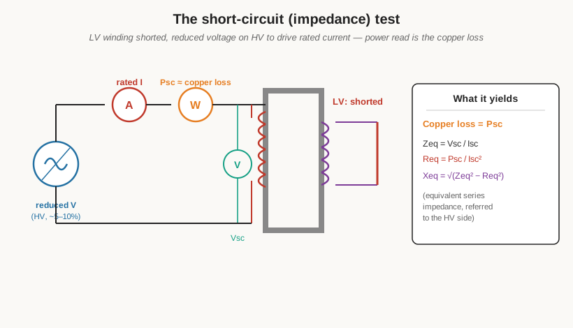
Now the logic runs the other way. The applied voltage is small — perhaps 5 to 10% of rated, the transformer’s impedance voltage — so the flux in the core is only that same small fraction of normal, and since core loss scales roughly with the square of the flux, the core loss during the short-circuit test is a fraction of a percent of normal and is negligible. But rated current is flowing in both windings, so the copper loss is at its full rated value. The short-circuit power Psc is therefore the copper loss at rated load, full stop — the same loss the design sheet of Volume 9 estimated as I²R in the two windings. The short-circuit test is usually run from the high-voltage side, because the reduced impedance voltage on the HV side is a comfortable few tens of volts, whereas applying the impedance voltage to the LV side would mean sourcing a very large current at a very small voltage.
The measurement yields the series arm of the equivalent circuit. The equivalent impedance referred to the tested side is simply the applied voltage over the current, Zeq = Vsc/Isc. The equivalent series resistance comes from the power, Req = Psc/Isc² — this is R₁ plus the secondary resistance referred across by n², the total copper resistance the load current sees. And the equivalent leakage reactance is the remaining side of the impedance triangle, Xeq = √(Zeq² − Req²). Those numbers are the same equivalent series impedance that leakage-inductance and DCR measurements approached from their own directions, now measured as a single lumped quantity under real rated current. Because the short-circuit test is run at low voltage, it is quite safe and quick, and it is the standard production test for the impedance of a power transformer.
Run together, the two tests are complete. The open-circuit test gives the shunt branch (Rc and Xₘ) and the core loss; the short-circuit test gives the series branch (Req and Xeq) and the copper loss; and the four elements are the equivalent circuit of Volume 2. From them the transformer’s performance at any load can be computed on paper — its regulation, its efficiency, its no-load and full-load behaviour — which is why these two low-power tests replace an expensive and difficult full-power load test in every transformer factory in the world.
13.7 Polarity and phasing: finding the dots
A transformer’s winding leads carry no inherent marking of which end is which, yet the relative polarity of the windings — the dot convention of Volume 1 — matters enormously the moment two windings must be combined: paralleling two secondaries for more current, series-connecting them for more voltage, wiring a centre-tapped rectifier, or hooking a multi-winding transformer into a circuit that assumes a particular phase. Connect two windings in the wrong relative polarity and, at best, their voltages subtract instead of add; at worst, paralleling two out-of-phase windings shorts them together through their own low impedance and destroys the transformer. The polarity test finds the dots with nothing more than a jumper wire, an AC source, and a voltmeter.
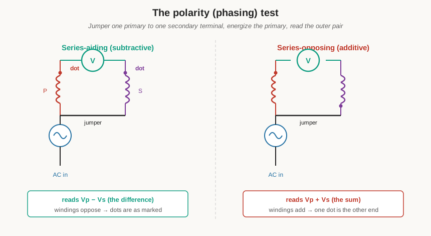
The method links one primary terminal to one secondary terminal with a jumper, applies a convenient AC voltage to the primary, and reads the voltage across the remaining outer pair — the free primary terminal and the free secondary terminal. Two outcomes are possible. If the meter reads less than the applied voltage — specifically the difference of the primary and secondary voltages — the windings are series-aiding in the way they were jumpered (this is the subtractive connection), and the jumpered terminals are the “unlike” ends. If the meter reads more than the applied voltage — the sum of the two winding voltages — the windings are series-opposing as jumpered (the additive connection). Either result unambiguously locates the dots: the tester now knows, for instance, that the top primary lead and the top secondary lead are the two dotted terminals, and can label the leads and wire the transformer into any configuration with confidence. On a low-voltage bench transformer the additive and subtractive readings are easy to tell apart; on a step-up transformer the additive reading can be large, so the test is run at a reduced applied voltage and the outer pair is treated as live. For a transformer the builder wound personally, the polarity is known from the winding direction and the lead-out sequence, but the test is the definitive confirmation and the standard way to verify an unmarked salvage part before trusting it.
13.8 Insulation resistance and hi-pot: the safety tests
Everything above characterises how a transformer performs. The insulation-resistance and hi-pot tests answer a different and more urgent question for any mains transformer: is it safe to energise at all? The isolation barrier between a mains primary and its secondary — the interleaving insulation, the margin tape, the bobbin walls, the reinforced or double insulation of Volume 5 — is a safety barrier whose entire job is to keep line voltage away from whatever a person can touch on the secondary side. A transformer that a builder wound personally must pass these tests before it is ever plugged in, because a winding fault or a nicked insulation film that the eye cannot see becomes, the instant the primary is energised, a lethal path from the mains to the user. This is not a performance nicety; it is the difference between a safe device and an electrocution.
The insulation-resistance test uses an insulation tester — a megohmmeter or “megger” — which applies a moderate, current-limited DC voltage (commonly 500 V or 1000 V for mains-class insulation) between two isolated parts and measures the leakage resistance, reading out in megohms or gigohms. The three measurements that matter are primary-to- secondary, primary-to-core (or frame), and secondary-to-core, each of which should read essentially open — hundreds of megohms into the gigohms for healthy insulation. A reading that has collapsed to a few megohms or less is contaminated, damp, or damaged insulation, and the transformer is condemned until the fault is found. The megohmmeter’s DC probe is gentle enough to be non-destructive, so insulation resistance is a good first screen and a good long-term monitor of a transformer’s condition.
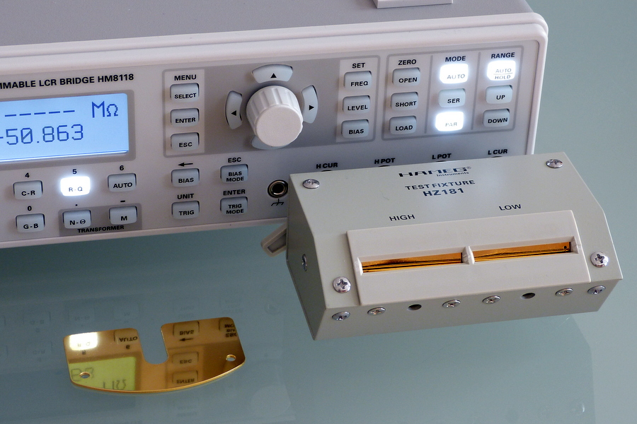
The hi-pot (high-potential, or dielectric withstand) test is the more demanding proof. Rather than measuring the insulation’s resistance, it stresses the insulation with a deliberately high test voltage — far above the working voltage — and confirms that it does not break down. The tester applies the voltage primary-to-secondary (and, where required, each winding to the core), holds it for a set time, usually 60 seconds for a type test or a second or two for a production test, and watches for breakdown current. For a mains transformer the test voltage is set well above the line voltage: the safety standards for mains transformers and appliances (the IEC 61558 and IEC 62368 families and their UL equivalents) require a dielectric-withstand voltage on the order of a few kilovolts across the primary-to-secondary barrier — commonly around 3 kV RMS AC for basic mains insulation and roughly double that for the reinforced or double insulation that a Class II part relies on, with the general rule of thumb being twice the working voltage plus about a thousand volts. The test can be run with AC (which stresses the insulation the way service does and also exercises the inter-winding capacitance) or with DC (which is easier on capacitive parts and lets the tester read the true leakage current). Either way the principle is the same: apply several kilovolts across the barrier that is supposed to keep the mains away from the user, and if it holds without flashover or excessive leakage, the barrier is sound. The hi-pot test is genuinely hazardous — the tester’s output is lethal by design — so it is done with the transformer isolated, the operator’s hands clear, and the high-voltage leads treated with the same respect as a live mains bus. A home-wound mains transformer that has not been hi-pot tested is an unknown, and a builder without access to a hi-pot tester should treat the insulation-resistance test as the minimum bar and the interleaving discipline of Volume 11 as the real guarantee.
13.9 Regulation and efficiency: the load test
Regulation and efficiency were defined in Volume 2 and estimated in the design of Volume 9; this is where they are confirmed on the finished part. Both can be computed from the open- and short-circuit parameters already measured — that is the whole point of those two tests — but they can also be measured directly with a load test, and comparing the two is a good sanity check on the equivalent circuit.
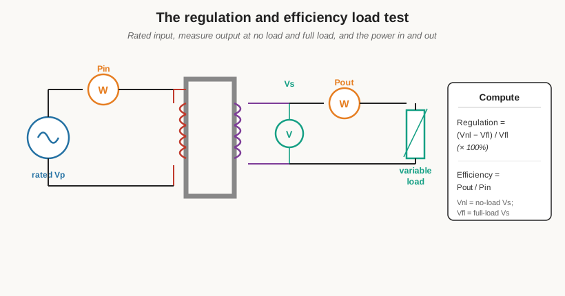
For regulation, the transformer is energised at its rated primary voltage and the secondary voltage is read first with no load connected (Vnl) and then with the load raised to rated full-load current (Vfl). The regulation is the drop between the two, expressed as a fraction of the full-load voltage: regulation = (Vnl − Vfl)/Vfl, usually quoted as a percentage. A stiff, low-leakage transformer with heavy copper shows a few percent; a small transformer with thin wire and loose coupling can sag 10% or more. The same figure falls straight out of the short-circuit test, because the voltage drop under load is the load current flowing through the equivalent impedance Req + jXeq, so the load test and the computed regulation should agree — and if they do not, the equivalent circuit is incomplete or a parameter was mis-measured.
For efficiency, two wattmeters read the input power Pin and the output power Pout at a given load, and the efficiency is simply their ratio, η = Pout/Pin. Because a transformer is a very efficient device, the two powers are nearly equal and the small difference is the sum of the core and copper losses, so measuring efficiency by subtracting two large nearly-equal numbers is inaccurate; the far better route, and the one the factory uses, is the loss-summation method — add the core loss from the open-circuit test to the copper loss from the short-circuit test, and compute η = Pout/(Pout + Pcore + Pcopper). This is why the two power tests matter so much: they let the efficiency be computed to a fraction of a percent from two easy low-power measurements, where a direct input-output measurement would need full rated power and still be less accurate. The efficiency also peaks, as Volume 2 showed, at the load where the copper loss has risen to equal the fixed core loss, and the two measured losses locate that peak exactly.
13.10 Temperature rise: the resistance method
A transformer’s rating is ultimately a thermal rating — it can deliver only as much power as it can shed the resulting heat without cooking its own insulation — so the temperature- rise test is what proves a design’s thermal budget (Volume 9) was honest. The elegant part is that the winding measures its own temperature, using the copper it is made of as a built-in thermometer, through the resistance method.
The physics is that copper’s resistance rises with temperature by a well-defined law: for copper, resistance is proportional to (234.5 + T), where T is in degrees Celsius and 234.5 is copper’s inferred zero-resistance temperature. Measure the winding’s cold DC resistance R₁ at a known ambient temperature T₁, then run the transformer at full load until its temperature stops rising (it reaches thermal equilibrium after an hour or several, depending on size), switch it off, and immediately measure the hot resistance R₂. The average winding temperature at the moment of switch-off follows from
T₂ = (R₂/R₁)·(T₁ + 234.5) − 234.5,
and the temperature rise is T₂ minus the ambient temperature during the run. Because the winding starts cooling the instant the power is removed, the hot-resistance reading is taken as fast as possible (or several readings are taken and extrapolated back to the instant of switch-off), and the ambient is tracked throughout. The resistance method gives the average temperature of the whole winding — not the hottest spot, which runs hotter — so a margin is kept between the measured average rise and the insulation class’s limit. A Class A system tolerates about 105 °C, Class B about 130 °C, Class F about 155 °C, and Class H about 180 °C (the insulation table of Volume 5 and Volume 14), and the measured average rise plus the ambient plus a hot-spot allowance must stay under whichever class the transformer was wound to. A transformer that runs cooler than its budget can be pushed harder; one that overshoots was under-designed — too small a core, too thin a wire, or too little window for the copper — and the test sends the builder back to the design engine.
13.11 No-load current and inrush: watching the exciting current
Two related observations round out the electrical picture, both of them about the current the transformer draws at and around switch-on. The no-load (exciting) current is what the open-circuit test already measured as I₀ — the small current a transformer draws with nothing connected to its secondary, feeding only the core loss and the magnetizing reactance. Watched on an oscilloscope through a current probe, it is not the clean sinusoid the source voltage is; it is a peaky, cusped waveform, distorted by the core’s nonlinear B–H curve, and its shape is itself diagnostic — a fatter, more distorted exciting current than expected means the core is being driven closer to saturation than intended, pointing at too few primary turns or too high an applied voltage for the core’s flux capacity.
Inrush is the far larger and more transient cousin. When a transformer is switched onto the mains at an unlucky point in the voltage cycle, the core can be driven deep into saturation for the first few cycles — because flux is the integral of voltage, switching on at a voltage zero-crossing asks the flux to swing to twice its normal peak, which the core cannot support, so it saturates and its inductance collapses, letting a large current flow limited only by the winding resistance. This inrush current can momentarily reach many times the rated current — ten to forty times is common for a mains transformer, and toroidal transformers, with their low loss and steep saturation, are notorious for the worst inrush. It decays over several cycles to a few dozen as the core losses damp the transient. The inrush is watched on an oscilloscope with a current probe on the primary and the transformer switched on repeatedly to catch the worst-case switching angle; the peak it reaches sizes the fuse (which must be slow-blow enough to ride through the inrush) and any inrush-limiting resistor or thermistor the circuit needs. It is a test worth doing on any transformer bound for a real product, because a transformer that trips its own breaker on switch-on is a transformer whose inrush was never characterised.
13.12 A bench summary
The tests of this volume form a short, ordered routine. Run in sequence on an unknown or newly wound transformer, they leave nothing important unmeasured, and each one answers a specific question the earlier volumes raised.
Table 1 — A bench summary
| Test | What it measures | Typical setup |
|---|---|---|
| Turns ratio | n = N₁/N₂; catches mis-tapped or shorted-turn windings | Low AC on one winding, read both voltages (or a TTR tester); secondary open |
| Winding resistance (DCR) | Copper resistance R₁, R₂; open/short faults; feeds temp-rise | 4-wire Kelvin milliohm-meter at the winding terminals, transformer at ambient |
| Magnetizing inductance Lₘ | Magnetizing current, low-frequency/bass response | LCR meter on one winding, other winding OPEN |
| Leakage inductance Lₖ | Regulation, HF roll-off, SMPS turn-off spike; coupling quality | LCR meter on one winding, other winding SHORTED |
| Open-circuit (no-load) test | Core loss; magnetizing branch Rc, Xₘ | Rated voltage on LV winding, HV open; read V, I₀, P₀ (wattmeter) |
| Short-circuit (impedance) test | Copper loss; series Req, Xeq | LV shorted, reduced V on HV for rated current; read Vsc, Isc, Psc |
| Polarity / phasing | The dots; safe series/parallel/centre-tap hookup | Jumper one primary to one secondary lead, AC on primary, read outer pair |
| Insulation resistance | Barrier integrity, P-to-S, P-to-core, S-to-core | Megohmmeter at 500/1000 V DC; expect hundreds of MΩ to GΩ |
| Hi-pot (dielectric withstand) | Isolation withstand for a mains part | Hi-pot tester, ~3–4 kV+ primary-to-secondary, 60 s, watch for breakdown |
| Regulation & efficiency | Voltage sag under load; loss fraction | Load test (Vnl vs Vfl; Pin vs Pout), or compute from OC + SC parameters |
| Temperature rise | Thermal margin against insulation class | Resistance method: cold vs hot DCR, T₂ = (R₂/R₁)(T₁+234.5) − 234.5 |
13.13 Measurement closes the loop
These tests are where the whole dive comes together. The turns ratio of Volume 1, the equivalent circuit of Volume 2, the core and copper losses of Volumes 2 and 4, the insulation safety of Volumes 5 and 11, the design targets of Volume 9, and the winding craft of Volumes 10 through 12 all become numbers on a meter here — measurable, checkable, and either matching the design or pointing at the fault that broke it. A transformer is not truly finished when it comes off the winder; it is finished when the turns ratio reads right, the DCR matches the wire table, the open- and short-circuit tests return the losses the design predicted, the polarity is confirmed, and — for anything that touches the mains — the hi-pot holds off several kilovolts without a flicker of breakdown.
That last point bears repeating as the note this volume ends on, because it is the one non-negotiable. A transformer that reads a few percent off in regulation is merely a mediocre transformer; a transformer whose primary-to-secondary insulation fails is a hazard. The performance tests reward good design and good winding; the safety tests are the gate a mains part must pass before it is trusted with a human on the other side of the barrier. Measure both, in that spirit, and the transformer that began the dive as an almost magical black box ends it as a fully characterised, fully trustworthy component.
The equations, constants, core and lamination tables, mains voltages, wire and current-density data, insulation-class limits, and safety-standard references that these tests draw on are gathered into the one-page reference apparatus of Volume 14, the final volume — a bench card that turns the whole fourteen-volume dive into something the builder can keep at the winder and the test bench alike.
Comments (0)