Transformers and Transformer Winding · Volume 7
Types I: Power and Audio Transformers
7.1 From the ideal to the shelf
The first six volumes built a transformer from the ground up: the mutual inductance and turns ratio of Volume 1, the leakage and magnetizing branches of the real device in Volume 2, the history in Volume 3, the cores and windings of Volumes 4 and 5, and the ampere-turn balance and impedance reflection of Volume 6. All of that machinery describes a transformer — a pair of coupled windings on a core. But nobody buys “a transformer.” A designer reaches for a mains transformer, a toroidal supply, a Variac, an isolation box, an output transformer, a 70-volt line matcher. Each is the same physics wearing a different set of compromises, tuned to a particular job.
This volume and the next are a guided tour of that catalogue. Volume 7 covers the two families a reader is most likely to hold in the hand: the power (mains) transformer that lives in the corner of every linear power supply, and the audio transformer that couples a valve amplifier to its loudspeaker. Along the way it treats the two close relatives of the power transformer — the autotransformer (and its sliding cousin, the Variac) and the isolation transformer — and it ends on the constant-voltage distribution transformer that a public-address system hangs from a single pair of wires. Volume 8 picks up the instrumentation, radio-frequency, and switch-mode families; Volume 9 turns from choosing a transformer to designing one.
The unifying question, asked of each type in turn, is the same three-part question an experienced engineer asks of any component: how is it built, what is it for, and what does it cost you? The costs are rarely money alone. They are weight, stray field, hum, inrush, bandwidth, isolation, and safety — and the whole art of picking a transformer is knowing which of those a given job can tolerate and which it cannot.
7.2 Mains and power transformers
A power transformer, also called a mains transformer when it works directly off the wall, does the most literal job in the catalogue: it takes the alternating voltage of the electrical supply — nominally 120 volts at 60 hertz in North America, 230 volts at 50 hertz across most of Europe and Asia, 400 hertz aboard aircraft — and changes it to one or more voltages a circuit can use. In a classic linear power supply it stands first in the chain, ahead of the rectifier, the smoothing capacitor of the Capacitors dive, and the regulator. Everything downstream inherits the voltage it hands over, and the isolation it provides is, for a mains-connected device, a safety barrier between the user’s fingers and the live supply.
7.2.1 Step-down, step-up, and the volt-amp rating
Most mains transformers step down: the secondary has fewer turns than the primary, so the output voltage is lower and — because power is conserved less the losses — the output current can be correspondingly higher. A 230-volt-to-12-volt supply transformer steps the voltage down by roughly nineteen to one and steps the available current up by nearly the same factor. A minority step up, for instance to run a 120-volt appliance from a 100-volt Japanese outlet, or to raise a low logic voltage to drive a display; the arithmetic is simply run the other way. The turns-ratio relationships of Volume 1 govern all of it, and the impedance-reflection rule of Volume 6 — that the primary sees the secondary’s load scaled by the square of the turns ratio — decides what the wall socket feels.
A power transformer is rated not in watts but in volt-amperes (VA), the product of its rated secondary voltage and the current it can deliver continuously without overheating. VA rather than watts because a transformer does not care about the phase of the load current — a reactive load draws current the transformer must carry and its windings must dissipate, whether or not that current does real work at the far end. The VA rating is ultimately a thermal rating: it is the loading at which the copper and core losses of Volume 2 raise the winding temperature to the edge of its insulation class (Volume 5). Push past it and the insulation cooks; the number is a promise about heat, not about magnetism.
7.2.2 EI versus toroidal: the trade that will not go away
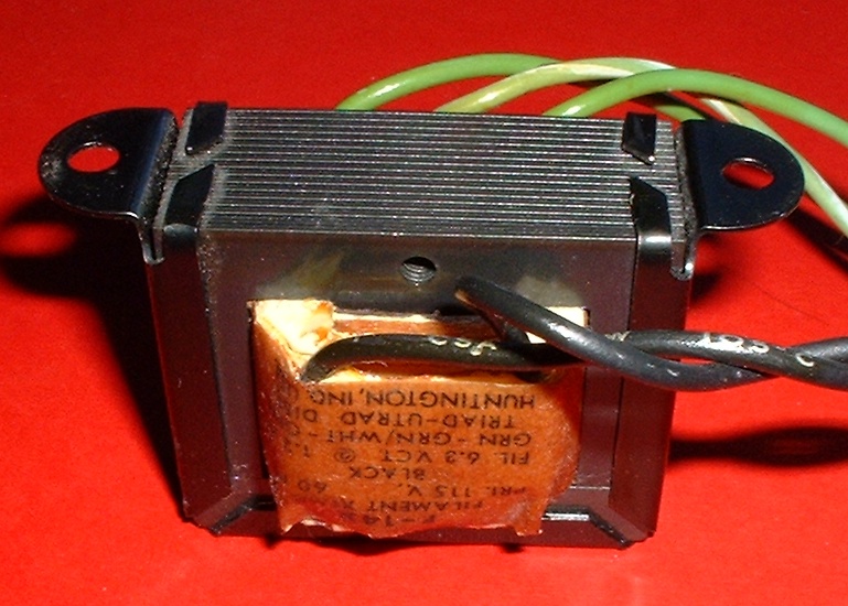
Volume 4 laid out the core forms in the abstract. In a mains transformer the choice narrows, in practice, to two: the EI (or shell) core stamped from E-shaped and I-shaped laminations, and the toroidal core wound from a continuous ribbon of grain-oriented silicon steel. Both are silicon steel; both run at line frequency; both do the same electrical job. Yet they feel utterly different in the hand and on the bench, and the difference is worth setting out plainly because it recurs in almost every power-supply decision an engineer makes.
The EI transformer is the old workhorse. Its stampings are cheap, its bobbin-wound windings are trivial to make on the machines of Volumes 10 and 11, and its butt-and-interleave assembly leaves a small, almost accidental air gap at the lamination joints. That tiny gap is a mixed blessing: it costs a little magnetizing current and a little efficiency, but it also tames the inrush, because a gapped core is harder to drive deep into saturation on the first half-cycle after power-on. The EI transformer’s real vices are that it is heavy and bulky for its rating, that it flings a noticeable stray magnetic field out of the ends of its windings — enough to induce hum in a nearby phono cartridge or audio input stage — and that its laminations can buzz audibly at twice the line frequency as magnetostriction flexes the steel.
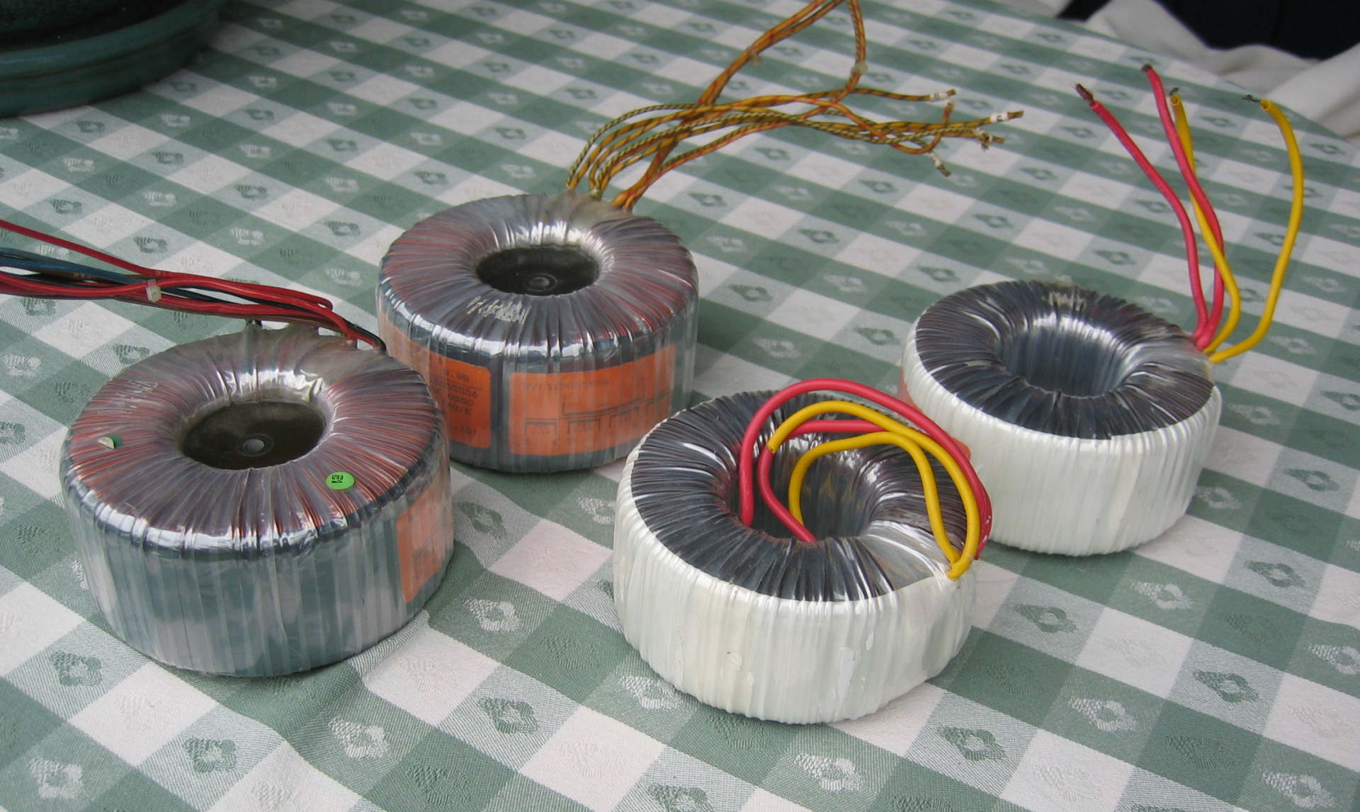
The toroidal transformer answers most of those vices. Its core is a doughnut of wound steel with the flux running continuously around the ring, along the grain of the oriented steel the whole way, with no joints and no gap. The windings are spread evenly around the ring. The consequences are striking, and they are the reason the toroid took over high-end audio and instrumentation supplies:
Table 1 — The toroidal transformer answers most of those vices. Its core is a doughnut of wound steel with the flux running continuously around the ring, along the grain of the oriented steel the whole way, with no joints and no gap. The windings are spread evenly around the ring. The consequences are striking, and they are the reason the toroid took over high-end audio and instrumentation supplies
| Property | EI (shell) core | Toroidal core |
|---|---|---|
| Core | Stamped E and I laminations, interleaved | Continuous grain-oriented ribbon, wound |
| Air gap | Small residual gap at the joints | Effectively none |
| Size and weight | Larger, heavier for a given VA | Roughly half the volume and weight |
| No-load (magnetizing) loss | Higher | Low — the gapless, along-grain path needs little exciting current |
| Stray external field | Noticeable; may need a shield can | Low — the closed ring is largely self-shielding |
| Audible hum | Can buzz (magnetostriction, loose laminations) | Quiet |
| Inrush current | Milder (the gap limits it) | High — often ten to forty times rated; soft-start advised |
| Winding | Easy on a bobbin | Needs a toroid winder threading wire through the hole |
| Cost | Low | Higher |
Two entries in that table deserve emphasis because they trip up the unwary. The first is inrush. A toroid’s virtue — a gapless, high-permeability core that stores almost nothing and needs almost no magnetizing current in steady state — is exactly its inrush vice. Switch it on at the wrong instant of the mains cycle and the core can be driven far into saturation on the first half-cycle, at which point its inductance collapses and it briefly behaves like a near-short across the line. Peak inrush currents of ten to forty times the rated current are routine, enough to trip a circuit breaker or weld a switch contact, and any serious toroidal supply pairs the transformer with an inrush limiter — an NTC thermistor, or a relay that shorts out a series resistor after a soft-start delay (the negative-temperature-coefficient thermistor and its cousins are treated in the Resistors dive). The gapped EI core, by contrast, saturates less abruptly and gets away with a milder surge. The second is winding: a toroid has no ends to slide a pre-wound bobbin onto, so every turn must be threaded through the central hole, which is why it needs the specialized toroid-winding shuttle of Volume 10 and why it costs more to build.
7.2.3 Dual primaries: one transformer, two continents
A great many power transformers carry two identical primary windings — a pair rated, say, at 115 volts each — rather than a single 230-volt primary. The reason is flexibility. Wire the two primaries in series and the pair accepts 230 volts, each winding taking half; wire them in parallel and the pair accepts 115 volts, each carrying half the total current. One part number thus serves both the North American and the European supply, selected by a link on a terminal block or a voltage-selector switch on the back panel. The secondary sees the same volts-per-turn either way, so the output is unchanged. The one discipline the dual-primary arrangement demands is phasing: when the two windings are paralleled they must be connected so their voltages add in the same sense around the loop. Get the phasing wrong and the two windings sit in opposition across the line, present almost no impedance to the difference, and draw a ruinous current that destroys the transformer in seconds. The dots of Volume 1’s dot convention exist precisely to prevent this; every dual-primary transformer’s datasheet marks the winding senses, and the builder observes them.
7.2.4 Center-tapped and multi-tap secondaries
Secondaries carry taps for two distinct reasons. A center tap is a connection brought out from the electrical midpoint of the winding, dividing it into two equal halves whose voltages are equal and opposite about that point. Its classic use is full-wave rectification: with a center-tapped secondary and just two diodes, each half of the winding feeds the load on alternate half-cycles, so the load sees a full-wave-rectified output while each diode and each winding-half works only half the time. The same center tap, left unrectified, provides the split positive-and-negative supply — plus and minus fifteen volts about a grounded center, say — that analog circuitry lives on. The filament secondary in Figure 1 is center-tapped for exactly this reason: the tap lets a hum-balancing potentiometer or a direct ground sit at the electrical center of the heater supply, cancelling the hum a valve’s heater would otherwise inject.
Multiple taps along a secondary serve a different end: they offer a choice of output voltages from one winding, or they accommodate variation in the incoming line. A universal-input mains transformer may bring out taps at 100, 110, 120, 220, 230, and 240 volts on the primary side so the installer can match the local supply and keep the secondary voltage on target. On the secondary side, taps let one transformer supply several rails, or let the builder trim the output to the exact voltage a regulator wants to see at its input. Every tap is simply a lead soldered to a chosen turn during winding — a technique Volume 11 treats in detail — and every tap is a small complication in the winding and a small compromise in the layer geometry, so the designer adds only the taps a design truly needs.
7.3 The autotransformer and the Variac
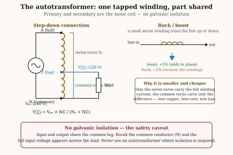
Slice away the assumption that primary and secondary must be separate windings and a leaner device appears. The autotransformer has a single tapped winding that serves as both primary and secondary at once. Part of the winding is shared between input and output; only the remainder is unique to one side. That sharing buys a real economy — and forfeits the one thing a two-winding transformer gives for free, which is isolation.
7.3.1 One winding, part shared — the economy
Consider a step-down autotransformer feeding a load at a voltage close to its input, say 240 volts down to 200. In a conventional two-winding transformer, the full load current flows through the whole secondary and the full input current through the whole primary; both windings carry their full share of the transmitted power. In the autotransformer the load taps off part of the same winding the source drives. Through the common portion — the part shared by input and output — flows only the difference between the input and output currents; through the series portion flows the through current. Neither part carries the full transmitted power. The nearer the ratio is to one-to-one, the smaller that difference current, and the more dramatic the saving: an autotransformer transmitting a given number of kilowatts at a modest ratio needs a core and a copper mass sized only for the fraction of the power that is actually transformed, not the whole throughput. Less copper, less iron, lower loss, less weight, lower cost — for a modest step up or down, the autotransformer wins on every count that a two-winding transformer measures itself by.
7.3.2 Buck and boost
The economy is starkest near unity ratio, and that is exactly where the buck-boost autotransformer earns its keep. Suppose a run of machinery sits at the end of a long feeder and the line voltage sags to 208 volts where the equipment wants 230. A small autotransformer with a series winding rated for only the difference — a few percent of the line — can be wired to add its voltage in phase with the line (boost) and lift the output to 230, or reversed to subtract (buck) and trim an over-high line down. Because the series winding handles only the small correction, not the full load power, the buck-boost transformer is a fraction of the size and cost of a full transformer of the same throughput. Utility distribution uses the same trick at scale: tap-changing autotransformers on the grid nudge line voltage up and down as load varies through the day.
7.3.3 The Variac: a continuously variable autotransformer
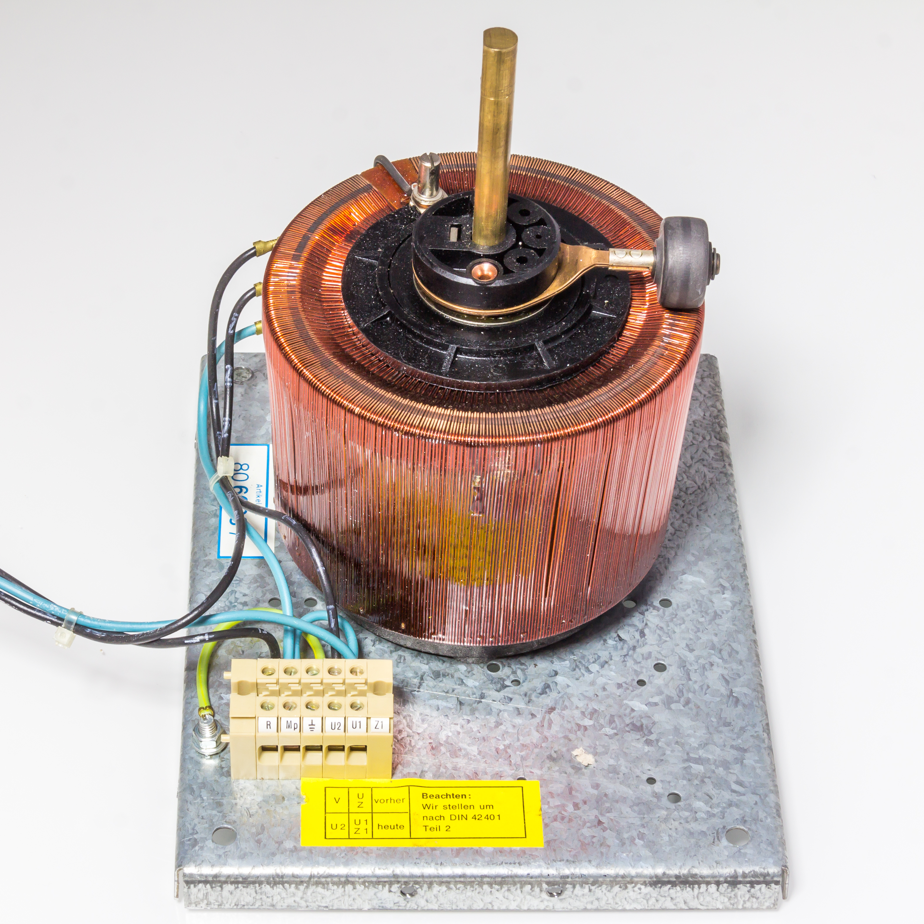
Fix the geometry of an autotransformer’s tap in place and one gets a set of discrete output voltages. Let the tap slide and one gets the variable autotransformer, universally called a Variac after the trade name General Radio gave its version. Its winding is a single layer wound around a toroidal core, and a strip along the top of that winding is left bare — the enamel ground away — so a carbon brush on a rotating arm can sweep across the exposed turns. Turning the knob moves the brush from turn to turn, tapping the winding at a continuously variable point and delivering any output from zero up to the full input voltage. Many Variacs wind a few extra turns beyond the line connection so the output can be pushed above the input — a 120-volt Variac that reaches 140 volts, useful for testing equipment at high-line conditions.
The Variac is one of the most useful instruments on a bench. It brings vintage equipment up slowly from zero so that decades-old electrolytic capacitors can re-form their oxide before full voltage hits them (the Capacitors dive treats re-forming); it sets the temperature of a soldering iron or the speed of a universal motor; it dials in exactly the line voltage a device is being tested at. Note that a Variac is rated by the current its brush and winding can carry, not by a fixed VA, because the brush conducts the full output current at whatever voltage is selected — a subtlety that catches out anyone who assumes it behaves like a constant-power source.
7.3.4 The warning that must always accompany the autotransformer
Every advantage of the autotransformer flows from the shared winding, and so does its one grave danger: it provides no galvanic isolation. Primary and secondary are electrically the same copper. There is no barrier between the input side and the output side — a fault or a hazardous voltage on one appears directly on the other. The specific failure that the shared winding invites is the worst of all: if the common conductor — the leg both sides return through — breaks or goes open, the full input voltage appears across the load, even though the device was set to deliver a low output. A Variac dialed to 10 volts, its common lead broken, will present the full 120 or 230 volts to whatever is plugged into it, with no warning. For this reason a Variac must never be treated as an isolation transformer, and a bench that needs a low, safe, isolated voltage uses a Variac feeding a separate isolation transformer, in that order, not a Variac alone. Where isolation is a safety requirement, the autotransformer is simply the wrong device — which is the cue for the type that exists to provide exactly that.
7.4 Isolation transformers
An isolation transformer is, electrically, the least interesting transformer in the catalogue and the most important for safety. It has separate primary and secondary windings, a one-to-one turns ratio, and therefore an output voltage equal to its input. It changes no voltage and matches no impedance. What it provides is the thing the autotransformer cannot: galvanic isolation — an unbroken insulating barrier between the two windings, with energy crossing only as magnetic flux, never as conducted current.
7.4.1 One-to-one, and why anyone pays for it
The value of that barrier is subtle until it is needed, and then it is everything. The mains supply has one of its conductors — the neutral — bonded to earth back at the service entrance. Touch the live conductor while standing on the ground and current flows through the body to earth: a shock. Feed the same equipment through a 1:1 isolation transformer and the secondary is floating — neither of its two output conductors is referenced to earth. Now touching one output conductor completes no circuit, because there is no earth-referenced return; a single accidental contact does not deliver a shock. This is why bench technicians who work on live, mains-connected chassis — the classic “hot chassis” of a transformerless television or switch-mode supply — run the equipment under test through an isolation transformer, so that a slip of the hand or an oscilloscope ground clip does not become a fault to earth. The isolation transformer does not make the voltage lower; it makes the circuit floating, which is a different and often more useful kind of safety.
The second everyday use is breaking ground loops. When two pieces of audio or instrumentation equipment are each earthed and also joined by a signal cable, current can circulate through the loop formed by their shared earth and the cable shield, injecting hum and noise. Inserting a 1:1 isolation transformer in the signal or the mains path breaks the metallic continuity of that loop while passing the wanted signal magnetically — the flux crosses the barrier, the ground-loop current does not.
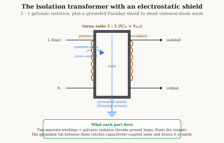
7.4.2 The electrostatic shield
Galvanic isolation blocks conducted current, but it does not by itself block capacitively coupled noise. The primary and secondary windings, however carefully separated, still face each other across a small inter-winding capacitance, and high-frequency common-mode noise — the fast switching trash of nearby digital and switch-mode gear — happily couples across that capacitance from one winding to the other, defeating the isolation at the frequencies where it is most wanted. The cure is an electrostatic shield, also called a Faraday screen: a thin grounded foil, or a single-layer winding of fine wire, placed between the primary and secondary and connected to earth. The shield intercepts the inter-winding capacitance and splits it in two — primary-to-shield and shield-to-secondary — draining the intercepted common-mode current to earth instead of letting it reach the secondary. A shielded isolation transformer therefore does two jobs at once: it blocks conducted current by galvanic isolation and shunts capacitively-coupled noise by the shield, which is why line-conditioning and sensitive-instrument supplies specify one.
7.4.3 Medical-grade isolation
The most exacting isolation transformers are built for medical equipment, where a patient may be connected to a device by electrodes or a catheter that offers a low-resistance path to the heart. Here the concern is not a fatal shock voltage but a fatal leakage current — the tiny current that flows through the transformer’s inevitable inter-winding capacitance and insulation resistance, which for a patient-connected device must be held to microampere limits set by the IEC 60601 medical safety standard. A medical-grade isolation transformer is designed and constructed — with extra-low inter-winding capacitance, guard shields, and reinforced insulation — to keep that leakage current far below the level that could disturb the heart. It is the same 1:1 transformer, taken to a construction extreme that the general-purpose part never reaches.
7.5 Audio and output transformers
The power transformer moves energy at one fixed frequency and cares nothing for waveform fidelity. The audio transformer faces the opposite demand: it must pass a band of frequencies — twenty hertz to twenty kilohertz for high fidelity, a narrower band for speech — with the ratios of those frequencies preserved. That single requirement, faithfulness across three decades of frequency, is what makes a good audio transformer hard to build and expensive to buy, and it dominates everything that follows.
7.5.1 The output transformer’s impedance-matching job
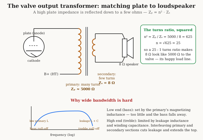
The archetype is the valve (tube) amplifier output transformer, or OPT. A power valve is a high-impedance current source: an output pentode wants to work into a load of several thousand ohms to develop its power efficiently, and it swings hundreds of volts to do so. A loudspeaker is a low-impedance load — nominally 4, 8, or 16 ohms — that wants amperes at a few volts. Connect the two directly and almost no power transfers; the valve, loaded by 8 ohms instead of 5,000, can barely develop any voltage across it. The output transformer is the impedance-matching gearbox between them. By the impedance-reflection rule of Volume 6, a transformer of turns ratio n makes a secondary load Zs appear at the primary as Zp equal to n-squared times Zs:
Z(primary) = n² · Z(secondary)
so the transformer is chosen to reflect the speaker’s 8 ohms up to the several-thousand-ohm load the valve wants to see. A single-ended output stage built around one pentode might want a 5,000-ohm plate load; reflecting 8 ohms up to 5,000 needs n-squared equal to 625, hence a turns ratio of 25 to 1. Push-pull output stages, treated below, present a plate-to-plate load in the same thousands of ohms — Hammond’s popular push-pull output transformers, for instance, are sold with primary impedances such as 4,000, 6,600, and 8,000 ohms plate-to-plate, matched to secondaries tapped at 4, 8, and 16 ohms. The OPT is, in one component, both the power-transfer path from valve to speaker and the impedance transformer that makes that transfer efficient.
7.5.2 Why wide bandwidth is hard
An ideal transformer would pass every frequency equally. A real one is bounded at both ends by the parasitics of Volume 2, and in an audio transformer those bounds fall right inside the audible band unless the designer fights them hard.
The low-frequency limit — the bass — is set by the primary magnetizing inductance. Recall from Volume 2 that the magnetizing inductance sits across the primary, drawing the exciting current that sets up the core flux. At high frequencies its impedance is large and it draws little; but its impedance falls with frequency, and at some low frequency it becomes comparable to the source and load impedances and begins to short out the signal. Below that frequency the transformer’s response rolls off. To push the roll-off down to 20 hertz the designer needs a large magnetizing inductance, which means many primary turns on a high-permeability core with a large cross-section — one reason a good bass-capable OPT is a heavy object.
The high-frequency limit — the treble — is set by two other parasitics working together: the leakage inductance, the flux that fails to link both windings, and the winding capacitance, the stray capacitance between turns and layers. The leakage inductance is in series with the signal and the winding capacitance is across it; together they form a low-pass filter, and above some frequency they roll the treble off and can ring at a resonance. The designer’s weapon here is interleaving, or sectioning: instead of winding the whole primary and then the whole secondary, the windings are split into sections and stacked alternately — primary, secondary, primary, secondary — so that primary and secondary turns are intimately woven together. Interleaving dramatically reduces the leakage inductance and extends the high-frequency response, at the cost of a more complex winding and somewhat higher inter-winding capacitance, so the designer balances the two. A wide-band audio output transformer is, in the end, a careful compromise between enough primary inductance for the bass and little enough leakage for the treble, wrung out of a fixed budget of turns and core.
7.5.3 Single-ended versus push-pull: the DC problem and the gap
The way the output stage is arranged changes the transformer profoundly, and the deciding factor is direct current in the core. In a single-ended stage, one valve conducts the whole waveform, and its steady plate current — a direct current of tens of milliamperes — flows through the whole primary winding. That DC magnetizes the core in one direction and drives it toward saturation, at which point it can carry no more AC signal flux and the transformer fails. The remedy, from Volume 4, is an air gap cut into the core: the gap lowers the core’s effective permeability, shifts its saturation point far out along the current axis, and lets it tolerate the DC bias. But the gap also lowers the magnetizing inductance, which — as just seen — worsens the bass, so a single-ended output transformer must be physically larger than a push-pull one of the same power to recover enough primary inductance despite the gap. This is a direct cost of the single-ended topology, paid in iron.
A push-pull stage splits the signal between two valves that conduct on opposite half-cycles, each driving one half of a center-tapped primary in the opposite sense. The two steady plate currents flow through the two primary halves in opposing directions, so their DC magnetizing effects cancel in the core. With no net DC bias, the push-pull output transformer needs no air gap: it keeps its full permeability and its full magnetizing inductance, so it can be smaller and lighter than a single-ended transformer of equal rating and reach deeper bass. The cancellation is a bonus at the signal level too — even-order harmonic distortion generated symmetrically in the two halves also cancels — which is one reason push-pull came to dominate power valve amplifiers. The price is the need for a phase-splitter ahead of the output valves and the demand that the two halves of the primary be wound as identically as possible, since any imbalance reintroduces the DC the topology was meant to cancel.
7.5.4 Interstage, input, and microphone transformers
The output transformer is the largest audio transformer but not the only one. An interstage transformer couples one amplifying stage to the next — the plate of one valve to the grid of the following — passing the signal while blocking the high DC plate voltage from the next grid, and optionally providing voltage step-up or a phase inversion to drive a push-pull pair. A microphone or input transformer sits at the front of the chain: it steps a low-impedance microphone (150 to 600 ohms, balanced) up to the higher impedance a valve grid or a first amplifier stage wants, and in doing so it delivers a free voltage step-up — the step-up ratio multiplies the tiny microphone signal before any active gain, improving the noise figure — while also converting the balanced, floating microphone line to an unbalanced input and rejecting common-mode hum picked up along the cable. All of these share the output transformer’s central difficulty: they must be flat and phase-accurate across the audio band, so they too are creatures of primary inductance at the bottom and leakage-plus-capacitance at the top, and they too are interleaved and carefully wound. They are simply smaller, because they carry signal rather than power.
7.6 Constant-voltage (70-volt and 100-volt) distribution
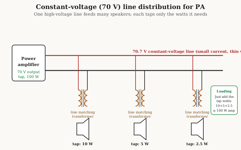
A public-address installation poses a problem the ordinary low-impedance speaker connection cannot solve: dozens of loudspeakers scattered across a building, at the ends of long cable runs, all fed from one amplifier. Wire 8-ohm speakers in parallel and the amplifier sees a fraction of an ohm and a colossal current; wire them in series and one failure silences the string, and the level of each depends on all the others. The resistance of the long, thin distribution cable, negligible against thousands of ohms, is ruinous against a few ohms. The answer, borrowed straight from the electrical grid, is to distribute the audio at a high voltage and low current and step it down at each speaker — a constant-voltage or 70-volt line system (100 volts in Europe and much of the world).
The scheme works like this. The amplifier is designed so that at its full rated power its output rises to a fixed line voltage — 70.7 volts in the North American convention, 100 volts elsewhere — regardless of how many speakers are connected. That fixed line runs, as a thin two-wire pair, to every loudspeaker in the building. At each speaker sits a small line-matching transformer that steps the 70-volt line down to the speaker’s low voice-coil impedance, and its primary is tapped in watts: the installer picks the 10-watt tap for a speaker that should be loud, the 2-watt tap for one in a quiet corridor, simply by choosing which primary tap to connect. Because each speaker draws only the power of its chosen tap, the total load on the amplifier is nothing more than the sum of the tap settings — pick taps that add up to no more than the amplifier’s rating and the system is correctly loaded. Speakers can be added, removed, or re-tapped without recalculating the whole system, the line current stays low so the cable can be thin and the runs long, and one shorted speaker transformer does not pull down the rest.
The particular number 70.7 is not arbitrary: it is 100 volts divided by the square root of two, so a sinusoidal line whose peak is 100 volts has an rms value of 70.7 volts, and 70.7 squared is very nearly 5,000 — a round figure that makes the power-and-impedance arithmetic (power equals voltage squared over impedance) come out in convenient numbers. The line-matching transformers themselves are ordinary small audio transformers, subject to the same bandwidth compromises as any other: the cheap ones roll off the bass and the top, which is why constant-voltage PA is prized for intelligible speech and background music rather than high fidelity. But for covering a large space cheaply and flexibly, no other scheme comes close, and the humble tapped distribution transformer is what makes it possible.
7.7 Choosing among them, and the bridge onward
Set the five families of this volume side by side and a selection logic emerges from the question each was built to answer.
Table 2 — Choosing among them, and the bridge onward
| Type | Turns ratio | Isolation? | Chosen for |
|---|---|---|---|
| Power / mains (EI) | Step down or up | Yes | Cheap, robust supplies; mild inrush; tolerant of stray field |
| Power / mains (toroidal) | Step down or up | Yes | Low weight, low stray field, quiet, efficient; needs inrush control |
| Autotransformer / Variac | Any, often near 1:1 | No | Modest ratio changes and adjustable voltage, cheaply and compactly |
| Isolation | 1:1 | Yes (its whole purpose) | Safety floating, ground-loop breaking, noise rejection with a shield |
| Audio / output | Impedance-matching | Yes | Matching a high source to a low load across the audio band |
| Constant-voltage line | Step down, tapped in watts | Yes | Distributing PA audio to many speakers over long runs |
The through-line is that no transformer is chosen for its ratio alone. A mains supply is chosen for its inrush behavior and stray field as much as its voltage; an autotransformer is chosen for economy and rejected wherever isolation is a safety requirement; an audio transformer is chosen for its bandwidth and its handling of core DC. The physics of Volumes 1 through 6 is the same in all of them; what differs is which compromise each family has decided to make.
This volume has surveyed the transformers that handle power and audio — the ones that live off the mains and drive loudspeakers. Volume 8 turns to the families that handle information and high frequency: the current and voltage transformers that let a meter read a heavy circuit safely, the tuned and broadband transformers of radio, the transmission-line baluns and ununs that match an antenna to its feed, and the flyback and forward transformers at the heart of every switch-mode power supply, where the line frequencies of this volume give way to the hundreds of kilohertz that let a modern supply shrink the iron of a mains transformer to a thumbnail of ferrite. And once both type surveys are complete, Volume 9 takes up the question this volume kept deferring — not which transformer to buy, but how to design one from the core up: the volts-per-turn from the EMF equation, the area-product that sizes the core to the job, and the current density that sizes the wire, turning the reader from a chooser of transformers into a maker of them.
Comments (0)