Transformers and Transformer Winding · Volume 14
Reference: Equations, Tables, and Further Reading
14.1 How to use this reference desk
The thirteen volumes before this one built the transformer up from mutual inductance and told the story of how it is made, used, wound, and tested. This one is the lookup apparatus that story leaves behind: the glossary, the design equations, the core and wire tables, the insulation and safety data, and the reading list, gathered so a builder can reach for a number at the bench without re-reading a chapter to find it. Nothing here is new. Every entry traces back to a full treatment elsewhere in the dive — “worked in the design volume,” “developed in the equivalent-circuit volume,” “covered in the winding volume” — and the numbers are the same numbers those volumes used, drawn from manufacturer literature (Hammond, Triad, Magnetics Inc., Metglas, Fair-Rite, Micrometals, TDK/EPCOS, Würth), the standards (IEC 60085, IEC 61558, IEC 62368-1, UL 5085), and the standard references (McLyman, Grossner, the ARRL Handbook).
One caution governs the whole desk. Magnetic parts are specified to tolerances, and their behaviour drifts with frequency, temperature, drive level, and load. The tables give representative, illustrative figures — enough to size a core, pick a wire, and set a safety margin — but a design that only just clears a limit on paper must be confirmed against the specific datasheet and the governing standard, and finally on the meter and the hi-pot set. Where a transformer touches the mains, the safety tables here point the way but do not replace the standard: creepage, clearance, and insulation are certified against the actual working voltage, pollution degree, and material group of the finished part.
Glossary
Alphabetized. Each entry is one to three sentences; the fuller treatment lives in the volume named in the text. Terms shared with the Coils companion dive (core materials, magnet wire, the winders) are given their transformer sense here.
Table 1 — Glossary
| Term | Definition |
|---|---|
| Ampere-turn balance | In a loaded transformer the secondary’s magnetomotive force is cancelled almost exactly by an equal, opposite primary MMF: Np·Ip ≈ Ns·Is. The core sees only the small net exciting MMF, which is why current transforms inversely to the turns ratio. |
| Amorphous metal (Metglas) | A rapidly quenched, non-crystalline iron-based alloy tape, B_sat ≈ 1.5–1.6 T with very low core loss; the core of high-efficiency distribution and low-kHz power transformers. |
| Area product (Ap) | The core’s window area times its magnetic cross-section, Ap = Wa·Ac (cm⁴); the single figure that scales with a transformer’s throughput power and the usual starting point for core selection. |
| Autotransformer | A transformer with one tapped winding, so primary and secondary share turns; smaller and cheaper than an isolated two-winding part for a modest ratio, but with no galvanic isolation. The variac is its adjustable form. |
| Balun / unun | A transformer that couples a balanced line to an unbalanced one (balun) or one unbalanced impedance to another (unun); at RF usually a transmission-line transformer on a ferrite core, giving ratios like 1:1, 4:1, or 9:1. |
| Bifilar winding | Two wires wound together as a pair for near-unity coupling and minimal leakage inductance; the basis of good transmission-line transformers, gate-drive transformers, and tightly coupled windings. |
| Copper loss (I²R loss) | The resistive heating in the windings, proportional to load current squared; measured by the short-circuit test and modelled as the equivalent series resistance R_eq referred to one side. |
| Core loss (iron loss) | The hysteresis plus eddy-current loss in the magnetic material, set by peak flux and frequency and nearly independent of load; measured by the open-circuit test and modelled by the shunt core-loss resistance R_c. Steinmetz: P_v ≈ k·fᵅ·Bᵝ. |
| Creepage | The shortest path along an insulating surface between two conductors; sized by working voltage, pollution degree, and the material’s comparative tracking index (CTI). Distinct from clearance. |
| Clearance | The shortest straight-line distance through air between two conductors; sized by working voltage and overvoltage (impulse) category. |
| Current density (J) | Winding current per unit copper area, in A/mm²; small transformers run ~2–4 A/mm², larger or forced-cooled ones less, trading temperature rise against copper mass. |
| Dot convention | The polarity marks that fix winding phase: currents entering the dotted ends produce aiding flux, and the dotted terminals rise and fall together in voltage. The bookkeeping that makes series-aiding, bucking, and phasing unambiguous. |
| EMF equation | The transformer’s foundational relation, V_rms = 4.44·f·N·B_max·Ac, tying induced voltage to frequency, turns, peak flux, and core area. The 4.44 is 2π/√2 (√2 to peak, 2π from the sinusoid, all over √2 back to RMS). |
| Efficiency (η) | Output power over input power, η = P_out/P_in = P_out/(P_out + P_cu + P_fe); peaks where copper loss equals core loss, and runs from ~90% in small mains parts to >99% in large distribution units. |
| Exciting (magnetizing) current | The small primary current drawn with the secondary open, magnetizing the core and supplying core loss; a few percent of rated current in a good design, rich in third harmonic from the B–H curve’s knee. |
| Flyback transformer | A coupled inductor, not a true transformer: it stores energy in a gapped core while the switch is on and delivers it to the secondary when the switch turns off; the heart of low-power isolated SMPS. |
| Forward transformer | A true transformer in a switch-mode converter, transferring energy while the switch conducts (with a reset winding or clamp to demagnetize the core each cycle); higher power than flyback. |
| Grain-oriented (GO) silicon steel | Iron with ~3% silicon, cold-rolled so its grains align with the rolling direction for low loss and high permeability along it; B_sat ≈ 1.9–2.0 T, the workhorse of 50/60 Hz power and audio cores. |
| Hi-pot (dielectric withstand) test | A production safety test applying a high AC or DC voltage (e.g. 1.5–4 kV) between windings, or winding-to-core, for one minute to prove the insulation withstands it without breakdown; pass/fail on leakage current. |
| Impedance reflection | A load Z_s on the secondary appears to the primary as Z_p = n²·Z_s, where n = Np/Ns; the mechanism behind impedance matching (audio output transformers, RF matching). |
| Interleaving | Splitting a winding and sandwiching primary and secondary layers to halve the leakage inductance (and, in laminations, alternating the E and I stack direction to close the magnetic gap). |
| Isolation transformer | A 1:1 (or other-ratio) transformer whose only job is galvanic separation of primary and secondary circuits, breaking ground loops and providing a safety barrier; specified by its isolation voltage and leakage current. |
| Leakage inductance (L_k) | The inductance from flux that links one winding but not the other; measured with the secondary shorted, it causes voltage regulation droop and rings with stray capacitance. Reduced by interleaving and good window fill. |
| Magnetizing inductance (L_m) | The large inductance of the primary seen with the secondary open, set by the core’s permeability and the turns; it draws the exciting current and, with R_c, forms the shunt magnetizing branch. |
| Nanocrystalline alloy | A fine-grained tape alloy (FINEMET, VITROPERM), permeability >100,000, B_sat ≈ 1.2–1.3 T, very low loss; superb common-mode chokes and high-frequency power and pulse transformers. |
| NiZn ferrite | Nickel-zinc ferrite: lower permeability (~15–800) but high resistivity, B_sat ≈ 0.3 T, useful from ~1 MHz into hundreds of MHz; the material of RF transformers, baluns, and wideband parts. |
| Open-circuit (no-load) test | Rated voltage applied with the secondary open; the wattmeter reads essentially core loss, and the readings yield the magnetizing branch (R_c, X_m). The dual of the short-circuit test. |
| Planar transformer | A transformer whose windings are copper traces in a multilayer PCB (or stamped foil) clamped between low-profile ferrite core halves; excellent height, repeatability, and thermal path for high-frequency SMPS. |
| Regulation | The rise of output voltage from full load to no load, Reg = (V_nl − V_fl)/V_fl, expressed as a percent; set by winding resistance and leakage reactance. Low regulation = a “stiff” transformer. |
| Reinforced insulation | A single insulation system giving protection equivalent to double insulation (two independent layers), certified for the working voltage; the barrier between mains and a user-accessible secondary. |
| Shell vs core form | Two core geometries: in core form the windings surround the core legs; in shell form (the EI stack) the core surrounds the central winding, enclosing and shielding it. |
| Short-circuit (impedance) test | The secondary is shorted and a reduced voltage raised until rated current flows; the wattmeter reads essentially copper loss, and the readings yield the series impedance (R_eq, X_eq) and the percent impedance. |
| Turns ratio (n) | The ratio of primary to secondary turns, n = Np/Ns = Vp/Vs = Is/Ip; it steps voltage one way and current the other, conserving volt-amperes (ideally). |
| Vacuum pressure impregnation (VPI) | Impregnating a finished winding with varnish or resin under vacuum then pressure to fill every void, locking turns, excluding moisture, conducting heat, and quieting buzz; the industrial form of dip-and-bake. |
| Volts-per-turn (V/N) | The core-and-frequency constant of a transformer, V/N = 4.44·f·B_max·Ac; every winding on that core has turns = its voltage divided by this figure. |
| Voltage / current transformer (VT/PT, CT) | Instrument transformers that scale a high voltage or large current down to a standard meter range (e.g. 120 V or 5 A / 1 A) with defined ratio and phase accuracy; the CT must never be operated with its secondary open. |
| Window utilization (K_u) | The fraction of the core window filled with active copper after bobbin, insulation, and slack; typically 0.3–0.5 for a mains transformer, lower where safety insulation is heavy. |
14.2 Design-equation cheat-sheet
The load-bearing equations of transformer design, with every variable and unit spelled out. SI throughout unless noted. These are worked at length in the design volume; here they sit on one card for the bench.
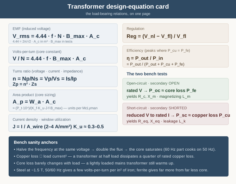
Table 2 — Design-equation cheat-sheet
| Quantity | Equation | Variables and units |
|---|---|---|
| EMF (induced voltage) | V_rms = 4.44·f·N·B_max·Ac | V_rms volts; f hertz; N turns; B_max peak flux density in tesla; Ac core cross-section in m². The 4.44 = 2π/√2, for a sine. |
| Volts-per-turn | V/N = 4.44·f·B_max·Ac | The core-and-frequency constant; every winding’s turns = its RMS voltage ÷ this. |
| Turns ratio | n = Np/Ns = Vp/Vs = Is/Ip | n dimensionless. Voltage scales with n, current inversely; ideally Vp·Ip = Vs·Is. |
| Impedance reflection | Zp = n²·Zs | A secondary load Zs appears on the primary multiplied by the turns ratio squared. |
| Area product | Ap = Wa·Ac | Wa window area, Ac core area (same length unit, so Ap in e.g. cm⁴); scales with throughput VA. |
| Area-product sizing | Ap ≈ (P_t·10⁴)/(K_f·K_u·J·f·B_max) | P_t apparent power (VA); K_f waveform factor (4.44 sine); K_u window utilization; J current density in A/cm². Units per McLyman — confirm the unit set before trusting a number. |
| Current density | J = I/A_wire | J in A/mm²; small natural-cooled transformers ~2–4 A/mm². Sets copper temperature rise. |
| Window utilization | K_u = (N·A_wire)/Wa | Copper area ÷ window area; ~0.3–0.5 typical, lower with heavy safety insulation. |
| Regulation | Reg = (V_nl − V_fl)/V_fl | No-load minus full-load output over full-load, as a fraction (×100 for percent). |
| Efficiency | η = P_out/P_in = P_out/(P_out + P_cu + P_fe) | Copper loss P_cu (load-dependent) plus core loss P_fe (nearly fixed); η peaks where P_cu = P_fe. |
| Open-circuit test | P_oc ≈ P_fe → R_c, X_m | Rated V, secondary open: wattmeter ≈ core loss; yields the magnetizing branch. |
| Short-circuit test | P_sc ≈ P_cu → R_eq, X_eq | Reduced V to rated I, secondary shorted: wattmeter ≈ copper loss; yields series R and leakage X. |
| Magnetizing / leakage | L_m: secondary open · L_k: secondary shorted | The two inductances the LCR meter reads from the two winding conditions. |
A handful of sanity anchors travel with these. A 50/60 Hz core running at ~1.5 T gives roughly 2–4 volts per turn per square inch of iron; ferrite at tens of kHz and ~0.2 T gives far more volts per turn from a far smaller core, which is the whole reason switch-mode supplies shrank. Copper loss tracks the square of load current, so a transformer at half load dissipates a quarter of its rated copper loss; core loss barely moves with load, which is why light-loaded mains transformers still warm up. And efficiency is highest not at full load but where the two losses cross.
14.3 Core-material comparison
Frequency first, then saturation flux, then loss — that is the order a core material is chosen, and this table is its menu. Permeability and B_sat vary by grade within each family; the ranges are illustrative, from manufacturer literature, and a real design confirms against the specific datasheet. This is the condensed form of the table in the core-materials volume, given its transformer sense.
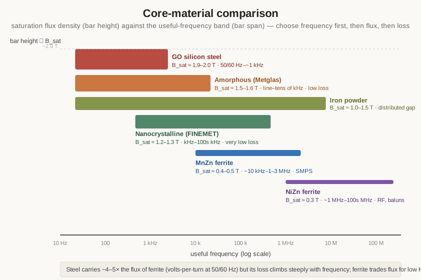
Table 3 — Core-material comparison
| Family | B_sat (approx.) | Useful frequency | Relative core loss | Typical transformer use |
|---|---|---|---|---|
| Grain-oriented silicon steel | ~1.9–2.0 T | 50/60 Hz – ~1 kHz | high above audio | Mains, audio/output, isolation, control |
| Non-oriented silicon steel | ~1.5–1.8 T | 50/60 Hz | moderate–high | Small mains, motors, low-cost EI |
| Amorphous (Fe-based, Metglas) | ~1.5–1.6 T | line – tens of kHz | low | High-efficiency distribution, chokes |
| Nanocrystalline (FINEMET) | ~1.2–1.3 T | kHz – hundreds of kHz | very low | Common-mode chokes, HF & pulse transformers |
| MnZn ferrite | ~0.4–0.5 T (~0.35 T hot) | ~10 kHz – 1–3 MHz | low (in band) | SMPS forward/flyback, LF wideband |
| NiZn ferrite | ~0.3 T | ~1 MHz – hundreds of MHz | low (in band) | RF transformers, baluns, wideband |
| Iron powder (carbonyl) | ~1.0–1.5 T | LF – VHF (distributed gap) | moderate–high | Chokes, some RF, DC-bias tolerant |
| Powdered permalloy (MPP) | ~0.75 T | LF – ~1 MHz | lowest of powders | Filter/resonant chokes, low-loss |
The single most useful contrast on this table is the first two rows against the ferrites: silicon steel carries roughly four to five times the flux density before it saturates, which buys volts-per-turn at 50/60 Hz, but its loss climbs so steeply with frequency that it cooks above the audio band. Ferrite throws most of that flux ceiling away in exchange for the low high-frequency loss that lets it run at tens of kHz to MHz. Both must stay well below B_sat when hot — ferrite’s saturation falls as it warms, so the working flux is set with the core hot, not cold.
14.4 Core forms and standard shapes
The transformer’s core geometry sets how the windings are assembled, how well the winding is enclosed, and how the flux path is closed. The common shapes, with their winding style and frequency home.
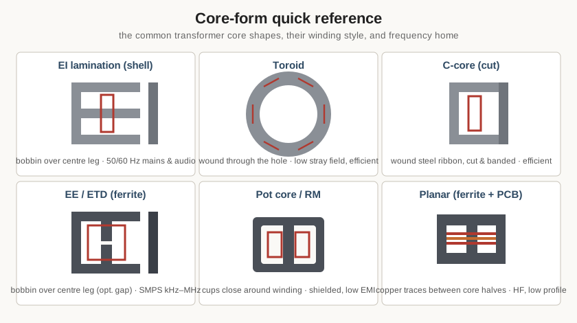
Table 4 — Core forms and standard shapes
| Core form | Construction | Winding style | Frequency / use |
|---|---|---|---|
| EI lamination (shell) | Stacked E and I steel laminations, interleaved | Pre-wound bobbin slipped over centre leg | 50/60 Hz mains & audio; the default power shape |
| UI / L lamination | Two U (or L) pieces butted | Bobbin over a leg | Mains, larger cores, gapped chokes |
| C-core (cut core) | Wound grain-oriented steel ribbon, cut and banded | Bobbin over one or both legs | Efficient mains & audio; low loss along grain |
| Toroid | Continuous wound steel ribbon or ferrite ring | Wound turn-by-turn through the hole | Low stray field, high efficiency mains; RF (ferrite) |
| EE / ETD / ER (ferrite) | Two ferrite E-halves, optional centre gap | Bobbin over centre leg | SMPS power transformers, tens of kHz–MHz |
| Pot core / RM | Ferrite cups closing around the winding | Bobbin inside the cups | Shielded, low-EMI SMPS & signal transformers |
| PQ / PM | Ferrite optimized for volume-to-window | Bobbin over centre leg | High-power-density SMPS |
| Planar (ferrite) | Low-profile E/I halves over a PCB winding | Copper traces in the PCB layers | High-frequency, low-profile SMPS, high repeatability |
| Binocular / multi-aperture (ferrite) | Two-hole ferrite block | Threaded transmission-line pairs | RF broadband transformers, baluns/ununs |
14.5 Standard mains voltages and frequencies
The supply a power transformer is designed to. Nominal single-phase values; tolerances (typically ±6–10%) and three-phase configurations layer on top. A transformer designed for one frequency must not be run at a lower one at the same voltage — halving the frequency doubles the flux and drives the core into saturation (which is why a 60 Hz transformer can overheat on 50 Hz, but a 50 Hz design runs cool on 60 Hz).
Table 5 — Standard mains voltages and frequencies
| Region / system | Nominal voltage | Frequency | Notes |
|---|---|---|---|
| North America | 120 V (240/120 split-phase) | 60 Hz | 120 V branch; 240 V across both legs |
| Europe / most of world | 230 V | 50 Hz | Harmonized 230 V; UK historically 240 V |
| Japan | 100 V | 50 Hz east / 60 Hz west | Split frequency; dual-frequency parts common |
| Three-phase (NA) | 208 / 480 V | 60 Hz | 120/208 Y and 277/480 Y distribution |
| Three-phase (Europe) | 400 V | 50 Hz | 230/400 Y |
| Aircraft / military | 115 V | 400 Hz | Higher f shrinks the core (per the EMF equation) |
| Rail / traction | 25 kV (and others) | 50/60 Hz or 16.7 Hz | 16.7 Hz European traction demands larger cores |
14.6 Wire, AWG, and current density
Bench-usable magnet-wire sizes; bare-copper diameter and area before enamel. The final column is the current at a representative 3 A/mm², the middle of the small-transformer range — not a hard rating. Design to 2 A/mm² for a cool, generous transformer, out to 4 A/mm² for a compact, warmer one, and confirm against temperature rise. This is the transformer-sense excerpt of the full AWG table in the magnet-wire volume (and the Coils dive); the mental checks hold — area ×2 every 3 gauges, diameter ×2 every 6 gauges.
Table 6 — Wire, AWG, and current density
| AWG | Bare dia (mm) | Area (mm²) | Ω/km (20 °C) | Current at 3 A/mm² |
|---|---|---|---|---|
| 14 | 1.628 | 2.08 | 8.28 | 6.2 A |
| 16 | 1.291 | 1.31 | 13.2 | 3.9 A |
| 18 | 1.024 | 0.823 | 20.9 | 2.5 A |
| 20 | 0.812 | 0.518 | 33.3 | 1.6 A |
| 22 | 0.644 | 0.326 | 52.9 | 0.98 A |
| 24 | 0.511 | 0.205 | 84.2 | 0.62 A |
| 26 | 0.405 | 0.129 | 133.9 | 0.39 A |
| 28 | 0.321 | 0.0810 | 212.9 | 0.24 A |
| 30 | 0.255 | 0.0507 | 338.6 | 0.15 A |
| 32 | 0.202 | 0.0324 | 538.4 | 97 mA |
| 34 | 0.160 | 0.0201 | 856.0 | 60 mA |
| 36 | 0.127 | 0.0127 | 1360 | 38 mA |
Nominal solid-copper AWG data (bare diameter, area, DC resistance at 20 °C); confirm build-grade overall diameter for fill-factor work. Outside North America wire is often sized directly in millimetres, and vintage British recipes use SWG, which does not equal the same-numbered AWG.
14.7 Insulation thermal classes and safety spacing
Two safety numbers govern a transformer: how hot the insulation may run, and how far apart the conductors must sit. The thermal class fixes the first. IEC 60085 assigns each insulation system a letter and a maximum continuous hotspot temperature; the winding’s hottest spot must stay below it for rated life.
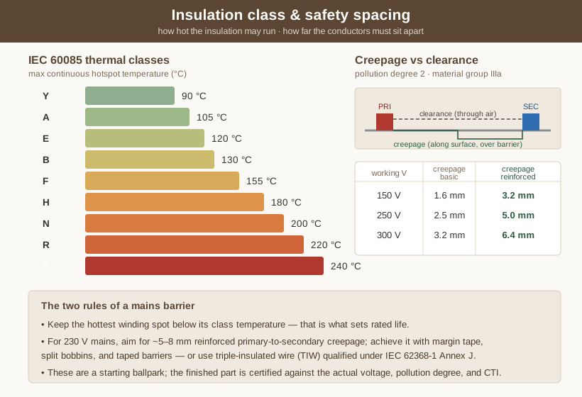
Table 7 — Insulation thermal classes and safety spacing
| Class | Max hotspot (°C) | Representative materials |
|---|---|---|
| Y | 90 | Unimpregnated paper, cotton, silk, plain enamel |
| A | 105 | Impregnated paper/cotton, oleoresinous enamel, oil-immersed |
| E | 120 | Polyurethane, epoxy, older polyester enamels |
| B | 130 | Mica, glass fibre with organic binder, polyester |
| F | 155 | Upgraded mica/glass/polyester systems, polyester-imide |
| H | 180 | Silicone, aramid (Nomex), polyester-imide + PAI |
| N | 200 | Higher-grade aramid/mica/silicone systems |
| R | 220 | Polyimide-based systems |
| S | 240 | High-temperature polyimide / inorganic systems |
The spacing numbers are set by working voltage, pollution degree, and (for creepage) the material’s comparative tracking index. Creepage is the surface path; clearance is the through-air gap. The quick guide below is for pollution degree 2 and material group IIIa (CTI 175–400), the common indoor-equipment case; reinforced insulation is taken as twice the basic creepage. Treat these as a starting ballpark — the finished part is certified against the actual standard.
Table 8 — Insulation thermal classes and safety spacing
| Working voltage (RMS) | Basic creepage | Reinforced creepage | Clearance (basic) |
|---|---|---|---|
| 150 V | ~1.6 mm | ~3.2 mm | ~1.5 mm |
| 250 V | ~2.5 mm | ~5.0 mm | ~2.0 mm |
| 300 V | ~3.2 mm | ~6.4 mm | ~3.0 mm |
For a 230 V mains transformer, then, a reinforced primary-to-secondary creepage in the 5–8 mm range is the working target — achieved by margin tape, split bobbins, and taped insulation barriers, or sidestepped by using triple-insulated wire (TIW) qualified under IEC 62368-1 Annex J, which builds the reinforced insulation into the wire itself and can shrink the required spacing. The winding volume covers the physical construction; the measurement volume covers proving it with the hi-pot test.
14.8 Transformer types: the master table
Every transformer family in one place — its core, its frequency home, its ratio character, and what it is for. The types are treated at length in the two “types” volumes; this is the selection map.
Table 9 — Transformer types: the master table
| Type | Typical core | Frequency | Ratio / role | Notes |
|---|---|---|---|---|
| Power / mains | EI or toroid, Si-steel | 50/60/400 Hz | Step up/down, multi-tap | The default; isolation + voltage change |
| Autotransformer / variac | Toroid, Si-steel | 50/60 Hz | Modest ratio, no isolation | Tapped single winding; smaller for its VA |
| Isolation | EI or toroid, Si-steel | 50/60 Hz | 1:1 | Galvanic barrier, breaks ground loops |
| Audio output (OPT) | EI/C-core, Si-steel | 20 Hz–20 kHz | Impedance match (Zp = n²·Zs) | Tube-to-speaker; wide band, low leakage |
| Interstage / line (70 V) | EI, Si-steel | audio | Match / distribute | Constant-voltage PA distribution |
| Current transformer (CT) | Toroid, Si-steel/ferrite | 50/60 Hz–kHz | Large I → 5 A / 1 A | Never open the secondary under primary current |
| Voltage / potential (VT/PT) | EI, Si-steel | 50/60 Hz | High V → 120 V | Metering-accuracy ratio and phase |
| RF / IF (tuned) | Powder/ferrite slug | kHz–VHF | Match / select | Part of a tuned circuit |
| RF broadband / balun / unun | Ferrite toroid/binocular | HF–VHF | 1:1, 4:1, 9:1 | Transmission-line transformer |
| Flyback (SMPS) | Gapped ferrite EE/ETD | tens of kHz–MHz | Store-and-release | Coupled inductor, isolated low power |
| Forward / push-pull (SMPS) | Ferrite EE/ETD/PQ | tens of kHz–MHz | True transfer while on | Mid/high power, needs core reset |
| Gate-drive / pulse | Ferrite toroid/EE | kHz–MHz | 1:1 isolation of drive pulses | Small, fast, tight coupling |
| Planar | Low-profile ferrite + PCB | 100s kHz–MHz | SMPS transfer | Low height, high repeatability |
14.9 Measurement tests: what each one yields
The bench tests that characterize a finished transformer, and the parameter each delivers. Worked in full in the measurement volume.
Table 10 — Measurement tests: what each one yields
| Test | Setup | Yields |
|---|---|---|
| Turns ratio | Apply known AC to one winding, read the other | n = Np/Ns = Vp/Vs (and available taps) |
| Winding resistance (DCR) | DC ohmmeter / 4-wire on each winding | Copper resistance; wire-size and shorts check |
| Magnetizing inductance L_m | LCR on primary, secondary open | Core permeability × turns; the magnetizing branch |
| Leakage inductance L_k | LCR on primary, secondary shorted | Uncoupled flux; regulation and ringing driver |
| Open-circuit (no-load) | Rated V, secondary open; watts, V, A | Core loss P_fe; R_c and X_m; exciting current |
| Short-circuit (impedance) | Reduced V to rated I, secondary shorted | Copper loss P_cu; R_eq, X_eq; percent impedance |
| Polarity / phasing | Series-connect and compare voltages; dot check | Winding sense (aiding vs bucking); the dots |
| Hi-pot (dielectric withstand) | High V winding-to-winding / winding-to-core, 1 min | Insulation integrity; safety pass/fail |
| Regulation | Measure V_nl and V_fl at rated load | Reg = (V_nl − V_fl)/V_fl |
| Efficiency | Measure P_in and P_out at load | η = P_out/P_in (or 1 − losses/P_in) |
| Temperature rise | Run at rated load; resistance-rise or thermocouple | Hotspot vs insulation class margin |
14.10 Safety standards index
The documents that govern a transformer’s safety, especially where it touches the mains. Cite the current edition; scopes are summarized.
Table 11 — Safety standards index
| Standard | Scope |
|---|---|
| IEC 61558 (series) | Safety of transformers, reactors, power supply units — the core transformer-safety standard; part 1 general, sectional parts for isolating, control, and mains parts. |
| IEC 62368-1 | Safety of audio/video, information and communication technology equipment; its Annex J qualifies triple-/multi-insulated winding wire (TIW) for reinforced insulation. |
| IEC 60601-1 | Medical electrical equipment — heightened isolation, leakage-current, and means-of-protection requirements for patient-connected supplies. |
| IEC 60085 | Electrical insulation — thermal classification (the Y…S class table above). |
| UL 5085 (1/2/3) | Low-voltage transformers — the North-American general, general-purpose, and class-2/3 transformer safety standards. |
| UL 1411 | Transformers and motor transformers for audio-, radio-, and television-type appliances. |
| UL 1446 | Systems of insulating materials — the recognized-insulation-system framework behind a thermal class. |
| MIL-PRF / MIL-STD (e.g. MIL-PRF-27, MIL-PRF-21038, MIL-STD-981) | Military-grade transformers and inductors: established-reliability performance and qualification. |
Further reading
Accurately named references behind the numbers in this dive. Editions vary; cite the one in hand.
Handbooks and textbooks
- Colonel Wm. T. McLyman, Transformer and Inductor Design Handbook (CRC Press). The definitive text on area-product core selection, window utilization, current density, regulation, and thermal design — the source of the sizing arithmetic here.
- Nathan R. Grossner, Transformers for Electronic Circuits (McGraw-Hill). Classic coverage of small-signal, power, and pulse transformer design and the equivalent circuit.
- Jerry Sevick, Transmission Line Transformers (Noble / SciTech). The standard reference on baluns, ununs, and broadband ferrite RF transformers.
- The ARRL Handbook for Radio Communications (annual). Practical RF transformer, balun, and ferrite/powder-core data and worked winding recipes.
- W. M. Flanagan, Handbook of Transformer Design and Applications (McGraw-Hill). Broad practical coverage across power, audio, and pulse types.
- E. C. Snelling, Soft Ferrites: Properties and Applications (Butterworths). The reference on ferrite material behaviour, loss, and permeability versus frequency.
Manufacturer literature and application notes
- Hammond Manufacturing — mains, audio/output, and choke transformer catalogues with real winding and impedance data.
- Magnetics Inc. — ferrite and powder-core catalogues; the Ferrite Cores and Powder Cores design guides (area product, core loss, DC-bias).
- Fair-Rite Products — ferrite material datasheets (43, 61, 77, and kin) for RF transformers, baluns, and beads.
- Micrometals — iron-powder and sendust core data and SMPS inductor/transformer application material.
- Würth Elektronik — Trilogy of Magnetics (application handbook) and the transformer/coupled-inductor datasheets.
- TDK / EPCOS, Ferroxcube — power-ferrite material data (N87 and equivalents), core geometries, and SMPS transformer design guides.
- Metglas — amorphous and nanocrystalline core data for high-efficiency and common-mode parts.
Standards
- IEC 61558 / IEC 62368-1 / IEC 60601-1 / IEC 60085 / IEC 60317 — transformer safety, equipment safety with the TIW annex, medical isolation, thermal classes, and magnet-wire specifications.
- UL 5085 / UL 1411 / UL 1446 — North-American transformer and insulation-system safety.
- IEC 63093 / IEC 62044 — standardized ferrite core shapes and core measurement methods.
14.11 The transformer in one page
A transformer is two or more windings sharing a magnetic core so that a changing current in one induces a voltage in the others — the reason it works only on AC. Everything about it follows from one equation, V = 4.44·f·N·B·Ac: the induced voltage rises with frequency, turns, peak flux, and core area, and dividing any winding’s voltage by the volts-per-turn constant gives its turns. It steps voltage up or down by the turns ratio n and steps current the other way, conserving volt-amperes; a load reflects back to the primary as n² times its impedance. The real part departs from the ideal through four measurable imperfections — magnetizing inductance and core loss (seen with the secondary open), and leakage inductance and copper loss (seen with it shorted) — and those four numbers, plus the turns ratio, fully describe it. Its quality is regulation and efficiency; its limits are saturation of the core and the temperature its insulation class allows; its safety, where it touches the mains, is the creepage, clearance, and reinforced insulation between primary and secondary, proven by hi-pot. Pick the core material for the frequency, size it by area product, wind it to the volts-per-turn, insulate it for the working voltage, and test it open, shorted, and at high potential — that is the whole of it.
This closes the Transformers and transformer winding dive, and with it the four-part passive-components program on research.fubsypoly.com. The four fundamental passives divide the work of a circuit cleanly between them. The Capacitors dive treated the part that stores energy in an electric field and resists a change in voltage; the Coils and coil winding dive, the part that stores energy in a magnetic field and resists a change in current; the Resistors dive, the part that stores nothing and simply dissipates, converting energy to heat as the reference against which the others are measured. The transformer is the fourth character and the one that couples and transforms — two coils sharing a core, using the field the inductor stores to move energy and change its voltage, current, and impedance from one circuit to another. Charge held, field held, energy dissipated, energy coupled: the brake, the two springs, and the lever. The companion dives develop the shared vocabulary — reactance and impedance, the equivalent circuit, self-resonance, tolerance and measurement — and the Coils dive in particular carries the core-material, magnet-wire, and winding-craft detail this dive extends to the two-winding case. The winding itself is done on real machines: the same coil winders that wind an inductor wind a transformer, and those are documented in The Model Shop → Coil Winders. With the four passives understood — what each stores, dissipates, or couples, and how each is built and wound — the rest of electronics is their conversation.
Comments (0)