Transformers and Transformer Winding · Volume 4
Core Materials and Construction
4.1 Why a transformer bothers with a core at all
A transformer is, at heart, two coils that share a magnetic field. One coil — the primary — is driven with an alternating voltage and pushes an alternating flux out into the space around it; the other — the secondary — sits in that flux and, by Faraday’s law, has a voltage induced in it. Everything a transformer does, from stepping mains down to five volts to matching a valve amplifier to a loudspeaker, follows from how completely those two coils share their flux. The core is the machine that makes the sharing near-total.
Left in air, the sharing is poor. The companion Coils dive laid out why: air is a feeble magnetic medium, so an air-cored coil sprays most of its flux into the surrounding room, and any second coil placed nearby catches only the fraction of field lines that happen to thread it. Two air-cored coils can be coupled — that is how a loosely-coupled RF transformer or a wireless-charging pad works — but the coupling is weak, leaky, and hard to control. For a power or audio transformer, where the reader expects nearly every volt applied to the primary to reappear (scaled by the turns ratio) at the secondary, weak coupling is fatal.
Slide a closed loop of magnetic material through both windings and the picture changes completely. A ferromagnetic core has a relative permeability µr from a few hundred to over a hundred thousand, which means it carries flux hundreds or thousands of times more readily than air. In the language of the magnetic circuit developed in the Coils dive — where magnetomotive force N·I drives flux Φ through a reluctance ℛ = l / (µ·A), exactly as voltage drives current through a resistance — the core is a low-reluctance path, a magnetic superhighway. Flux launched by the primary would far rather run around the easy iron loop, threading the secondary on the way, than struggle out through the high-reluctance air. So the core does two jobs at once: it concentrates the flux, multiplying the field a given current produces, and it channels that flux around a closed path that deliberately passes through both windings. The result is a shared common flux that links the two coils almost perfectly — the physical basis of the turns-ratio relationship unpacked in Volumes 1 and 6.
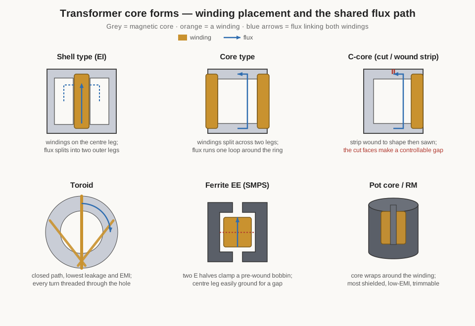
Nothing magnetic is free, and the core charges for its services in exactly the coin the Coils dive catalogued: core loss (hysteresis plus eddy currents, burned as heat every cycle), saturation (a hard flux ceiling beyond which the iron carries no more and the transformer stops transforming), and temperature dependence of every one of those quantities. This volume does not re-derive those mechanisms — the reader who wants the B–H loop, the eddy-current physics, and the material families from first principles will find them in the Coils dive’s core-materials volume. What follows here is the transformer-specific half of the story: the particular shapes iron and ferrite are cut into so that two windings can share a flux, the grain-oriented steel and laminations that make a mains transformer possible, the way the flux path is engineered to link primary and secondary, and — the practical payoff — how the job a transformer must do (50-hertz mains, a 200-kilohertz switcher, a broadband RF balun, a common-mode filter) sorts the materials as cleanly as a sieve.
4.2 The two demands, and the frequency that settles them
Every transformer core is a compromise between two wishes that pull in opposite directions, and understanding the pull is most of the subject.
The first wish is for a lot of flux from a little core. A transformer’s voltage rating is set by how much flux its core can swing through its cross-section, captured by the transformer EMF equation carried in full in Volume 9: the volts per turn are proportional to f·B·A, the product of frequency, peak flux density, and core cross-sectional area. For a fixed operating frequency and a fixed number of turns, more volts means more flux density B or more area A. Since iron is heavy and expensive, the designer wants B as high as the material will allow — which means a high saturation flux density, Bsat, and a high permeability so that a modest magnetising current is enough to reach it. This wish points straight at silicon steel, whose Bsat of nearly 2 tesla is the highest of any common core material.
The second wish is for low loss at the operating frequency, and it fights the first. Every trip a core makes around its B–H loop dissipates the loop’s enclosed area as heat (hysteresis loss), and every changing flux induces eddy currents in the core metal that dissipate more (eddy loss). Hysteresis loss climbs roughly in proportion to frequency; eddy loss climbs with the square of frequency. A solid or coarsely-laminated iron core that is a model of virtue at 50 hertz becomes an intolerable heater at 50 kilohertz, where its eddy losses have risen a millionfold. Above a few kilohertz the designer is forced to abandon bulk steel for a material that scarcely conducts — a ferrite — and accept its far lower Bsat as the price of survival.
That tension is the whole engine of core selection, and frequency is the master variable that resolves it. At line and audio frequencies, loss is manageable and the designer takes the high flux of silicon steel. As frequency climbs into the tens and hundreds of kilohertz of switch-mode power, loss dominates and forces the move to ferrite, trading four-fifths of the flux ceiling for resistivity that shuts eddy currents down. Higher still, into the megahertz of RF, an even lower-permeability, higher-resistivity ferrite takes over. Sort the materials by the frequency at which their loss becomes tolerable and the entire menu falls into order; that ordering is the spine of this volume and of the selection table at its end.
4.3 Silicon steel: the mains and audio workhorse
For everything that runs at the frequency of the power grid — 50 hertz in most of the world, 60 in North America, 400 in aircraft — and for audio transformers up through the top of the hearing range, the core is made of silicon electrical steel: iron alloyed with roughly 3% silicon and rolled into thin sheets. The silicon does two useful things. It roughly quadruples the electrical resistivity of the iron, which throttles eddy currents at the source, and it reduces the hysteresis loss and magnetostriction (the faint mechanical hum a transformer makes as its domains flex). Too much silicon makes the steel brittle and hard to roll, so about 3% is the practical ceiling; the material is a silicon-iron alloy rather than pure iron precisely to buy that resistivity.
The prize silicon steel offers is the highest saturation flux density of any ordinary core material — roughly 1.9 to 2.0 tesla — with grades such as the AK Steel / Cogent M-6 running to around 2.0 T. That tall ceiling is why the mains transformer in every appliance and the giant on the utility pole are built from it: high Bsat means a lot of flux through a modest cross-section, and by the EMF equation a lot of volts per turn, so the core can be small and the winding short. In practice the designer does not run the steel all the way to Bsat — that would invite saturation on every voltage peak and on the cold-start inrush surge (Volume 6). Mains cores are worked at a peak design flux of about 1.2 to 1.7 tesla, leaving headroom for high line voltage, temperature, and transient over-flux.
4.3.1 Grain orientation: making the iron care which way the flux runs
Ordinary iron is magnetically the same in every direction. The great trick of modern electrical steel is to make it not — to align the microscopic crystal grains so that the material magnetises far more easily along one axis than any other, then to arrange the core so the flux always runs along that easy axis. This is grain-oriented (GO) silicon steel, developed by Norman Goss in the 1930s, and the crystal alignment it produces is still called the Goss texture. Rolling and annealing the strip lines the iron’s easy-magnetisation crystal direction up with the rolling direction of the sheet. Flux driven along that rolling direction meets low hysteresis loss and reaches high permeability at modest field; flux driven across it does neither. A GO steel core is therefore always cut and stacked so the flux path lies along the grain — which is exactly why the wound C-cores and cut cores described below, with their continuously-wound strip, extract the best from the material.
Not every core can keep its flux along a single direction. In rotating machines, and in some cheaper or three-phase transformer cores where the flux must turn corners, non-oriented silicon steel — grain-random, magnetically uniform, cheaper, but lossier and lower in permeability along any given axis — is used instead. For a single-phase transformer built from stamped E and I pieces, the flux does turn corners at the yoke, so the very best GO grades give up some of their advantage; the wound strip cores keep it.
4.3.2 Why laminate, and how thin
The reason a silicon-steel core is built from a stack of thin insulated sheets rather than a solid block is the eddy current, treated at length in the Coils dive and only recalled here. A solid metal core is itself a shorted turn: the changing flux induces circulating currents that swirl through the core’s own resistance and dissipate energy for nothing, while their opposing field shoves the main flux out toward the surface. Slice the core into thin sheets, each coated with an insulating oxide or varnish so the insulation lies across the eddy paths, and the circulating currents are confined to each sheet. Their loops shrink, and the eddy loss falls with roughly the square of the lamination thickness — halving the sheet quarters the loss.
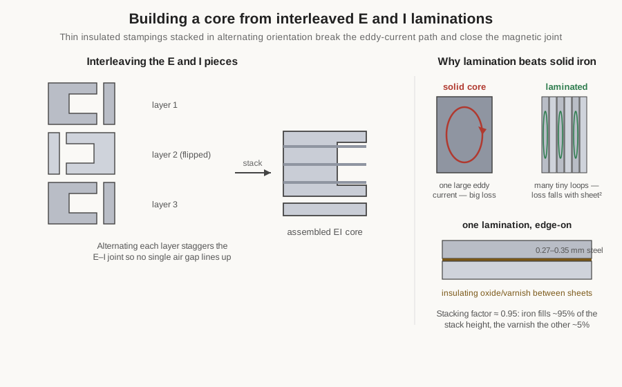
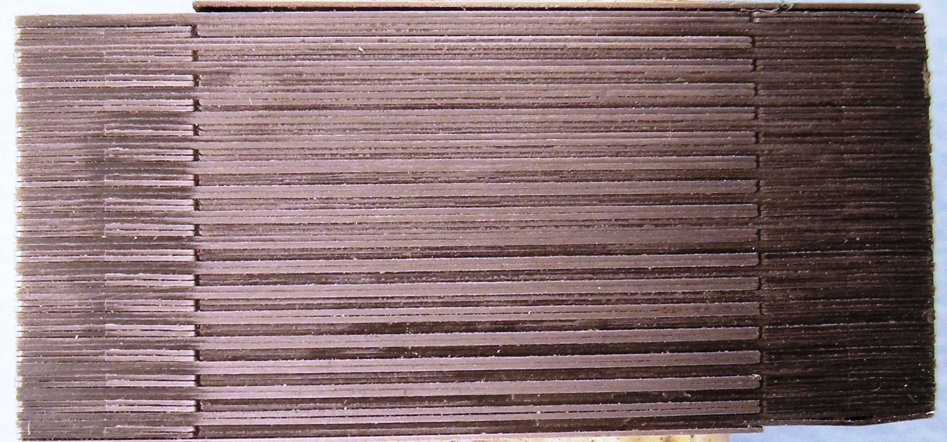
That square law sets the thickness against the frequency. At 50 and 60 hertz the standard laminations are about 0.35, 0.30, or 0.27 millimetres thick (the thinner, lower-loss grades cost more and go into efficiency-critical distribution transformers). For 400-hertz aircraft power the sheet is thinned toward 0.1 to 0.2 millimetres; push much past a kilohertz and the laminations would have to be so thin, and so numerous, that the whole approach becomes absurd — which is the boundary at which ferrite takes over. A real stack is never solid iron: between the sheets lies the insulation, and a little air. The fraction of the stack’s height that is actually magnetic steel is the stacking factor, typically about 0.95 to 0.97 for these thicknesses. The designer must remember it, because the magnetic cross-section that carries flux is the stacking factor times the physical stack dimension — the other few percent is varnish, and carries nothing.
4.4 Core forms in laminated steel
A core’s material sets its magnetic behaviour; its shape, or form, sets how the two windings are arranged around it, how tightly they couple, how much flux leaks, and what the core costs to build. Silicon steel is worked into a handful of standard forms, and each suits a different job.
4.4.1 EI and UI stampings, and the interleaved stack
The commonest and cheapest form stamps the steel into two shapes: an E, and a straight bar called an I. Stack the E and I together and the E’s three legs plus the I’s closing bar make a core with two windows — the openings the winding passes through. A closely related pair, the U and the I (UI), makes a single-window core. Stamping is fast and wastes little steel, and the punched pieces are stacked to whatever thickness the volt-amp rating demands.
The subtlety is the joint. Where the E meets the I there is inevitably a hairline air gap, and an air gap in a mains transformer’s main flux path is unwanted — it raises the magnetising current and the hum. The fix is interleaving: the laminations are stacked in alternating orientation, one layer with the I on the right, the next flipped with the I on the left, so that the E–I joints of successive layers never line up. The flux crossing a joint in one layer simply detours through the solid iron of the layer above or below, and the effective gap of the assembled stack falls almost to nothing. This is why a mains transformer core is stacked leaf by leaf, alternating, rather than as two pre-assembled blocks — a detail that returns in the hands-on stacking of Volume 11. (A transformer that is meant to have a gap — a few are — is instead butt-stacked, all the E’s together and all the I’s together, so the gap is real and controllable.)
4.4.2 Shell type versus core type: two ways to share the flux
How the winding sits on the core divides laminated transformers into two families, and the difference is worth seeing clearly because it governs coupling, leakage, and shielding.
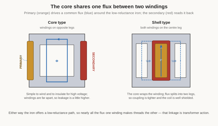
In the core type, the winding is split between the two legs of a single-window (UI-style) core — primary on one leg, secondary on the other, or half of each on both. The flux runs one loop around the ring, threading both legs. Core-type construction is simple to wind and easy to insulate for high voltage, because the two windings can be kept physically apart on separate legs; it dominates large power and distribution transformers, where insulation clearance matters more than the last decibel of coupling. Its price is a little more leakage flux — field that links one winding but not the other — because the coils are separated.
In the shell type, both windings are stacked concentrically on the centre leg of an EI core, and the outer legs of the core wrap around them like a shell. The flux driven up the centre leg splits, half returning down each outer leg. Because the iron surrounds the winding, coupling is tighter, leakage lower, and the winding is partly shielded from stray external fields. Shell construction is the usual choice for smaller mains and electronics transformers and for audio output transformers, where tight coupling and low leakage inductance directly improve performance. The two arrangements are the laminated-steel expression of a general truth revisited throughout this dive: wrap the core around the winding for coupling and shielding; wrap the winding around the core for simplicity and insulation.
4.4.3 Wound cores: the toroid and the C-core
Stamping throws away the grain-orientation advantage every time the flux turns a corner at a joint. Two forms avoid the corners by winding the steel as a continuous strip, keeping the flux along the grain the whole way around.
The tape-wound toroid winds a long ribbon of grain-oriented steel into a closed ring. The flux runs smoothly along the rolling direction with no joint and no gap, so the toroid has the lowest loss, the lowest magnetising current, the least leakage, and the least external stray field of any form — a toroidal mains transformer is famously quiet and cool, and radiates so little that it can sit close to sensitive circuitry. Its drawback is entirely mechanical, and it is the drawback of every toroid: there is no way to slip a pre-wound bobbin on, so every turn must be threaded through the hole, on a special ring-winding shuttle machine (Volume 10) or, painfully, by hand (Volume 11). That makes toroids more expensive to wind and awkward to tap, but for a low-noise, high-efficiency mains supply the magnetic advantages win.
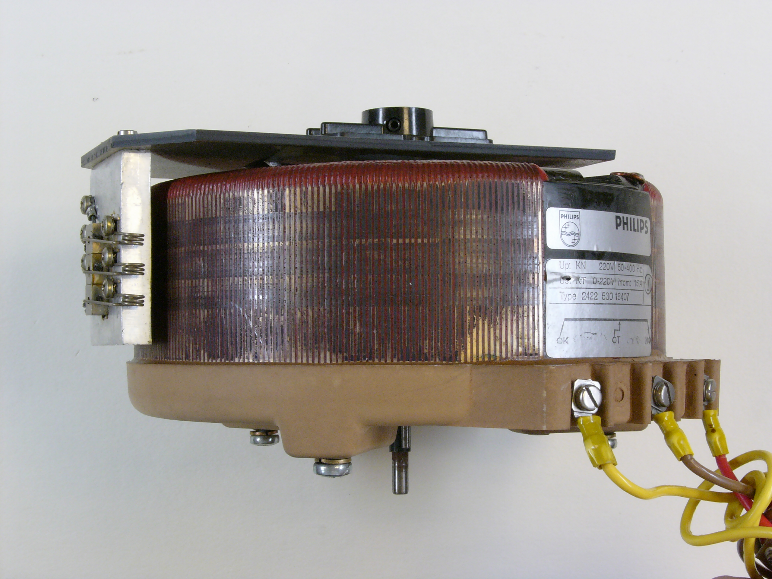
The C-core, or cut core, is the compromise between the toroid’s grain-perfect strip and the EI’s easy assembly. Steel ribbon is wound into a rectangular loop, bonded, then sawn across into two C-shaped halves. The halves are clamped around a pre-wound bobbin and their cut faces mated. The flux still runs along the grain around most of the path, so a C-core keeps much of the wound-strip advantage, while the cut lets the winding be made off the core and dropped on. The mating faces are precision-ground so their residual gap is tiny — or, when a gap is wanted (in a choke or a gapped transformer), ground back to a controlled dimension and shimmed. C-cores are common in higher-quality audio and industrial transformers and in gapped filter chokes.
4.5 Ferrites: the switch-mode and RF core
Push the frequency above a few kilohertz and silicon steel’s eddy loss makes it unusable no matter how thin the laminations. The material that replaced it, and made switch-mode power supplies and modern RF practical, is the soft ferrite — a sintered ceramic of iron oxide with manganese-zinc or nickel-zinc, treated fully in the Coils dive and recalled here for its transformer role. Being a ceramic, a ferrite has an electrical resistivity millions of times that of iron; eddy currents can barely flow in a material that scarcely conducts, so a ferrite carries flux into the megahertz with negligible eddy loss. The price is a much lower saturation flux density, roughly 0.3 to 0.5 tesla — a quarter of steel’s — so a ferrite transformer needs either more turns, more core area, or (the usual answer) a much higher operating frequency to carry the same power. That last point is the whole reason switch-mode supplies run at tens or hundreds of kilohertz: at high frequency the EMF equation’s f is large, so even ferrite’s small B yields ample volts per turn, and the transformer shrinks to a fraction of the size and weight of its 50-hertz cousin.
Ferrites come in two families that between them span an enormous range of frequency:
- Manganese-zinc (MnZn) ferrite is the higher-permeability (initial µr roughly 1,000 to over 10,000, power grades near 2,000–2,300), lower-resistivity branch, with Bsat around 0.4 to 0.5 T at room temperature. It is the material of choice from a few kilohertz up to roughly 1 to 3 megahertz — precisely the band of switch-mode power conversion. The main transformer and output choke of nearly every off-line power supply are wound on MnZn ferrite.
- Nickel-zinc (NiZn) ferrite is the lower-permeability (µr from single digits to about 800), far higher-resistivity branch, with Bsat lower still, around 0.25 to 0.35 T. Its resistivity lets it work from a few megahertz to hundreds of megahertz, which makes it the material of RF and broadband transformers, baluns, RF chokes, and the ubiquitous ferrite bead and clamp-on suppressor. The rule of thumb is blunt: MnZn for power and lower frequency, NiZn for RF and higher.
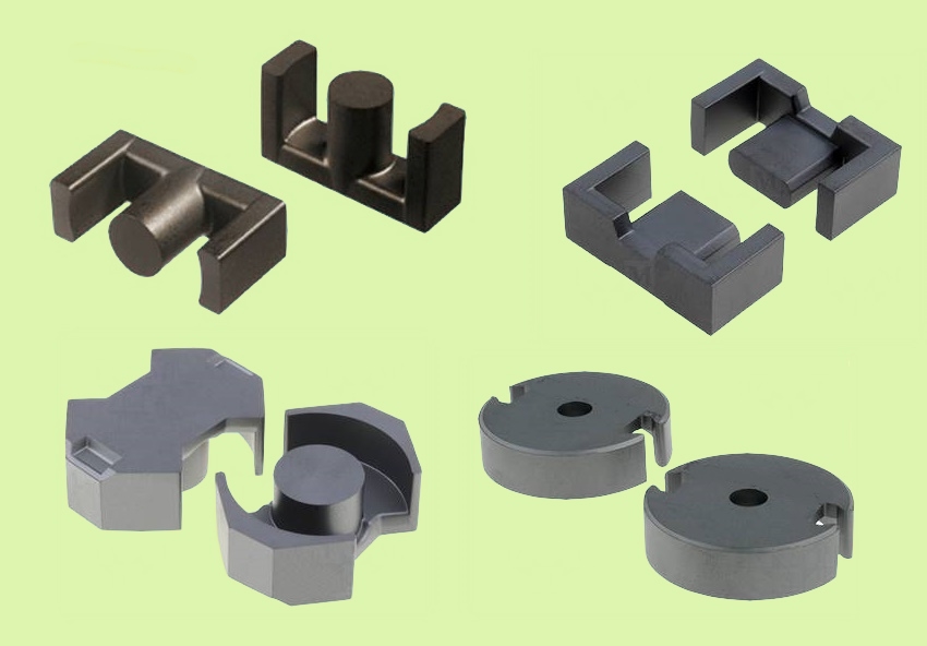
Because a ferrite is moulded rather than stamped, it can be pressed into shapes a laminated core cannot manage, and an entire family of bobbin cores has grown up around the switch-mode transformer. Two half-cores clamp around a plastic bobbin that carries the pre-wound coil, so the winding is made cheaply off the core on a machine and the assembly snapped together — the ferrite equivalent of the EI’s bobbin trick, but with the freedom of moulding. The workhorses are the EE, ETD, EFD, ER, RM, PQ, and P (pot) core families, each a different balance of window area, winding breadth, cross-section, and how much of the coil the core encloses (and so shields). The ETD and ER shapes have round centre legs that make winding easier and shorten the mean turn; the EFD is low-profile for slim supplies; the RM and pot cores wrap almost entirely around the winding for the best shielding and stability; the PQ optimises the ratio of core volume to winding volume for power density. For the flattest, highest-power-density supplies, planar cores dispense with wound wire altogether and use flat copper spirals etched into a multilayer printed circuit board sandwiched between two flat ferrite plates — superb for cooling and manufacturing consistency (Volume 8).
Two cautions ride with every ferrite, both from the Coils dive and both load-bearing for transformer design. Its already-modest Bsat falls with temperature — a MnZn core good for 0.5 T cold may manage only 0.35 T at 100 °C — so the saturation margin must be checked at the maximum operating temperature, not on the bench. And its Curie temperature (the point at which it abruptly stops being magnetic) is low for power grades, often 200–250 °C, so a ferrite driven into thermal runaway can cross its Curie point and lose its transformer action entirely.
4.6 Powdered iron, amorphous, and nanocrystalline
Between laminated steel and ferrite sit two families that fill important transformer niches.
Powdered-iron and powder cores — carbonyl iron, sendust (Kool Mµ), MPP, High Flux — are made by coating fine magnetic grains with insulation and pressing them into a core. The insulation between grains blocks eddy currents (as lamination does for sheet), but it also acts as a microscopic distributed air gap woven through the whole volume. That distributed gap gives these materials a soft, gradual saturation and a good tolerance of DC bias, which makes them the natural core for the inductor-like magnetics of power conversion — output chokes, power-factor-correction chokes, and the gapped energy-storage “transformer” of a flyback — rather than for a true power transformer, where their higher loss tells against them. Their properties and trade-offs are covered in full in the Coils dive; their relevance here is that a flyback transformer is really a coupled inductor that must store energy without saturating, and a distributed-gap powder core does that job with no discrete gap to grind.
Amorphous metal (Metglas) and nanocrystalline alloy (FINEMET, VITROPERM) are the high-performance tape-wound materials, ribbon only microns thick wound into toroids and cut cores. Amorphous iron-based alloy is quenched so fast the atoms never crystallise; it reaches Bsat around 1.5 to 1.6 T with far lower loss than silicon steel, which is why it now cores a large share of new high-efficiency distribution transformers on the grid — the standing no-load core loss of a pole transformer runs 24 hours a day for decades, so even a small loss reduction pays for the pricier core. Nanocrystalline alloy goes further: Bsat around 1.2 to 1.3 T, initial permeability that can exceed 100,000, and very low loss, which makes it the premium choice for common-mode chokes, EMI-suppression transformers, and high-frequency power transformers where its enormous permeability and low loss are worth a steep price. Both are the materials one reaches for when efficiency or EMI performance justifies the cost that keeps them out of everyday designs.
4.7 Saturation and the flux ceiling
Of all the numbers on a core datasheet, Bsat is the one the designer looks up first, because it is a hard wall and hitting it wrecks the transformer.
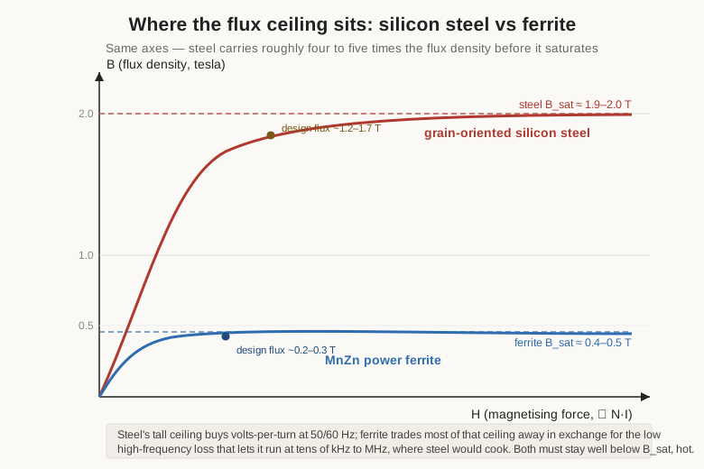
Recall from the EMF equation (Volume 9) that the peak flux density in a transformer core is set by the applied voltage, the frequency, the turns, and the core area — not by the load. Raise the voltage or lower the frequency and the flux swing grows. Push it past the material’s Bsat and the iron runs out of magnetic domains to align: B stops rising however hard the primary drives, the incremental permeability collapses toward that of air, and the winding — which had been a high-inductance, high-impedance coil kept in check by its own back-EMF — suddenly looks like a short length of wire. The magnetising current spikes enormously, no longer limited by the core’s inductance, and the transformer stops transforming. In a mains transformer this shows up as the inrush surge at switch-on (the core can be driven to twice normal flux on the first half-cycle if the switch closes at the wrong instant) and as overheating and buzzing if the line voltage runs high or the frequency low; in a switch-mode supply a saturating transformer dumps its uncontrolled magnetising current straight into the switching transistor, which usually dies. Saturation and its consequences are pursued in Volumes 6 and 9; the takeaway here is why the design flux always sits well below Bsat — comfortably under 2 T for steel, under a hot-derated 0.3 T or so for ferrite — with margin for high line, high temperature, and transient over-flux.
A true power transformer runs on symmetric AC, so its flux swings evenly about zero and never accumulates a DC bias. But some transformers must carry a steady DC through a winding — a flyback’s coupled inductor, a transformer feeding a rectifier with an unbalanced duty, a current sense in a DC-carrying line — and that DC bias adds a steady offset to the flux, marching the operating point toward saturation before the AC swing even begins. The cure is the air gap: a deliberate short break in the magnetic path.
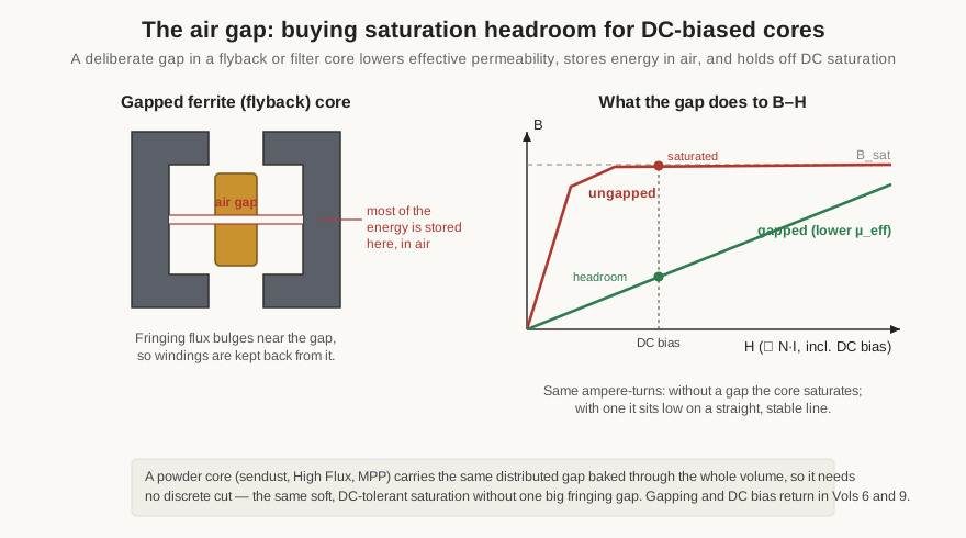
The gap works exactly as the Coils dive derived. Because air has µr = 1, even a fraction of a millimetre of gap presents a reluctance that dwarfs the whole ferrite path around it, so the gap seizes control of the magnetic circuit. The effective permeability drops, the B–H characteristic is sheared over into a straight, shallow, stable line that reaches Bsat only at a much larger ampere-turn — that is, a much larger current — and most of the energy ends up stored in the gap itself, in loss-free air. That is precisely what a flyback transformer wants, since a flyback stores energy in its core during one half of the switching cycle and delivers it during the other; without a gap its high-permeability ferrite would saturate almost at once. The powder cores of the previous section carry the same benefit as a distributed gap baked through the material, needing no discrete cut and suffering none of the fringing-flux loss a single big gap causes near its edges. The gapping arithmetic is carried to worked numbers in Volume 9.
4.8 Choosing the material and the form for the job
Core selection collapses, in practice, to a short and stubborn sequence that the whole of this volume has been building toward. Begin with frequency, because it eliminates most of the menu at a stroke: line and audio frequency point at silicon steel (or amorphous for efficiency); tens of kilohertz to a megahertz point at MnZn ferrite; the RF megahertz point at NiZn ferrite. Then choose a form to match how the two windings must sit and how much leakage, shielding, and winding cost the application will bear: an EI shell for cheap, tightly-coupled electronics transformers; a core-type UI for easy high-voltage insulation; a toroid for the lowest loss and stray field; a bobbin-core EE/ETD or a planar for switch-mode power; a NiZn toroid or binocular core for broadband RF. Then confirm the flux and current stay below the hot-derated Bsat, gapping the core if DC bias demands it. Only then weigh loss, temperature rise, size, and cost.
The table below gathers the sorting. The permeability and Bsat figures vary by grade within each family; the ranges are representative, drawn from manufacturer literature (Cogent/AK Steel for GO silicon steel, Fair-Rite and TDK/EPCOS for ferrite, Magnetics Inc. for powder cores, Proterial/Hitachi Metals for Metglas and FINEMET), and any real design must confirm against the specific datasheet.
Table 1 — Choosing the material and the form for the job
| Transformer job | Typical frequency | Material | Bsat (approx.) | Usual core form |
|---|---|---|---|---|
| Mains power (appliance, electronics) | 50 / 60 Hz | Grain-oriented silicon steel | ~1.9–2.0 T | EI / UI laminations, toroid |
| Low-noise, high-efficiency mains | 50 / 60 Hz | GO silicon steel | ~1.9–2.0 T | Toroid (tape-wound) |
| High-efficiency grid distribution | 50 / 60 Hz | Amorphous (Metglas) | ~1.5–1.6 T | Wound / cut core |
| Audio output & interstage | 20 Hz – 20 kHz | GO silicon steel (thin grades) | ~1.9–2.0 T | EI shell, C-core |
| Aircraft / avionics power | 400 Hz | Silicon steel (thin laminations) | ~1.9–2.0 T | EI, C-core |
| Switch-mode power (off-line, DC-DC) | ~20 kHz – 1 MHz | MnZn ferrite | ~0.4–0.5 T | EE / ETD / EFD / PQ / RM bobbin, planar |
| Flyback / DC-biased coupled inductor | ~20 kHz – 1 MHz | Gapped MnZn ferrite or powder core | ~0.4–0.5 T (ferrite) | Gapped EE / ETD, powder toroid |
| RF & broadband, baluns / ununs | ~1 MHz – 300 MHz | NiZn ferrite | ~0.25–0.35 T | Toroid, binocular / multi-aperture |
| EMI / common-mode suppression | kHz – MHz | Nanocrystalline or ferrite | ~1.2–1.3 T (nano) | Toroid |
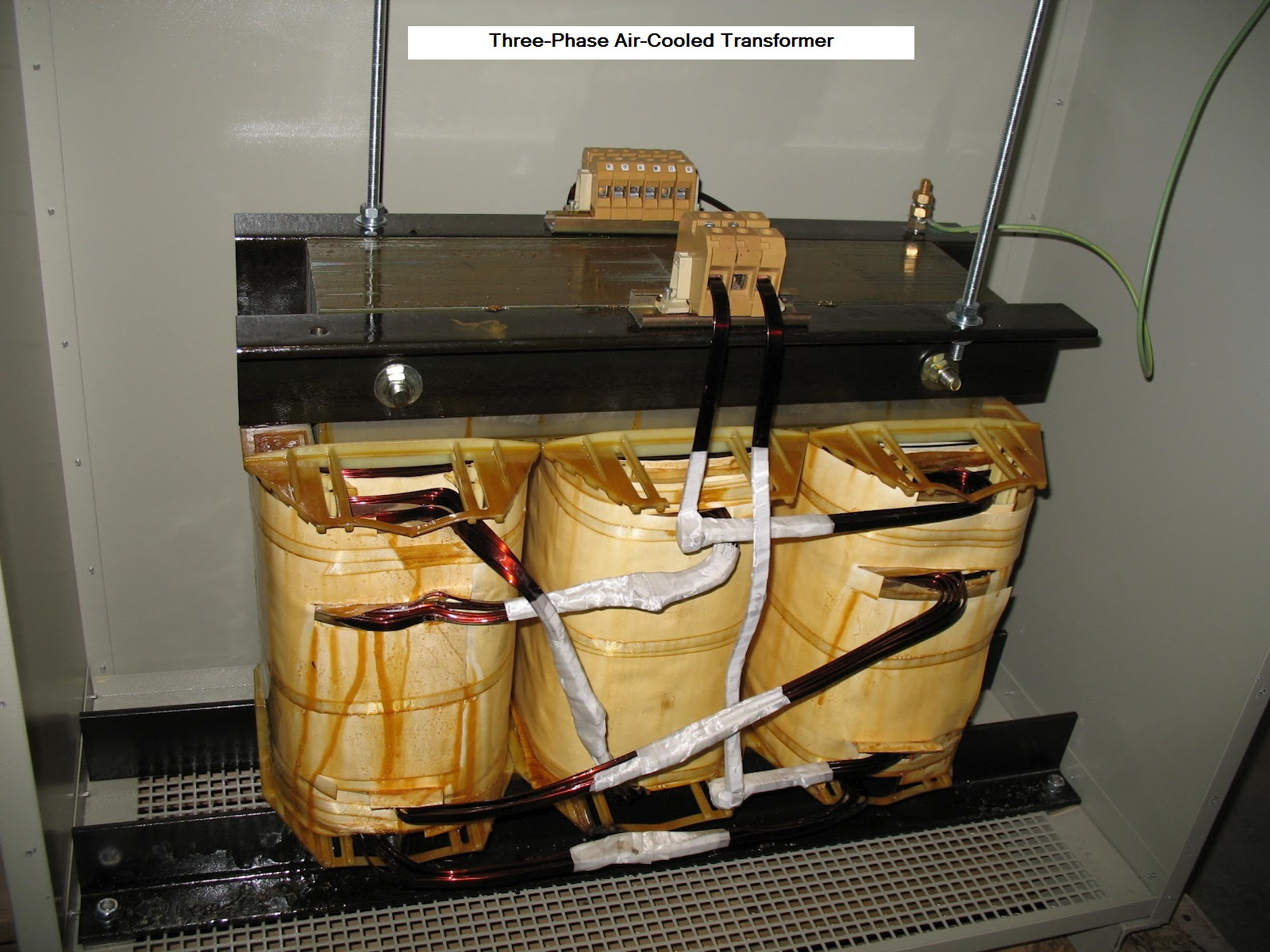
With the material and form chosen, the core is set, and everything the transformer can and cannot do is largely decided. What remains is the arithmetic of turns and flux and wire size (Volume 9), the magnet wire and insulation that keep the windings apart and safe (Volume 5), and the patient craft of actually winding a bobbin, interleaving the insulation, and stacking the laminations (Volumes 10 through 12) — where the core forms surveyed here reappear as the physical hardware on the winder’s bench.
Comments (0)