Transformers and Transformer Winding · Volume 11
Winding Your Own: Technique and Practice
11.1 From the machine to the hand
The previous volume set up the winding machine and took it apart in the mind: the spindle that turns, the counter that lands the exact turn, the traverse that lays the flat layer, the tensioner that seats the copper without stretching it. All of that is the machine’s contribution, and it is the mechanical, repeatable half of the job. This volume is about the other half — the judgement and the handwork that turn a spinning bobbin into a finished, safe, two-winding transformer. It is the hands-on heart of the dive, and it is where the difference between a transformer that works for a decade and one that hums, runs hot, or fails a safety test is actually decided.
The companion Coils dive already devoted a volume to winding technique for a single inductor — anchoring a start, laying even turns, controlling tension, terminating an end. That material is not repeated here; a primary is wound exactly as a choke’s winding is wound, and the reader who wants the fundamentals of laying one clean layer should read that volume first. What this volume adds is everything that makes a transformer harder than a choke: it has more than one winding, so the windings must be built up in sequence with insulation between them; that insulation on a mains part is a safety barrier between lethal potential and the user’s hand, not a mere convenience; the turns must hit an exact ratio, so taps and leads must come out at precise counts and be dressed to survive; and the finished coil has to be married to a core — an interleaved lamination stack, or a toroid that was wound onto its ring — and then locked down with varnish and proven with a high-voltage test before it is ever plugged in. Those additions are the subject of the pages that follow, and they lean heavily on this dive’s own Volume 5 (magnet wire and the insulation system) and Volume 10 (the machines), and on the design arithmetic of Volume 9 that says how many turns of what wire, in how many layers, the coil must contain.
11.2 Preparing the bobbin and reading the design
The wind begins not at the spindle but at the design sheet. Before a single turn is laid, the winder must know from the Volume 9 design four things about each winding: the total turn count, the wire gauge, the number of layers that count will take, and where any taps come out. The layer count is the one beginners skip and experts calculate first, because it governs the whole build-up. It follows directly from the bobbin’s usable winding width and the wire diameter: divide the winding width, less the two end margins, by the insulated diameter of the wire, and the result is the number of turns that fit across one layer; divide the total turns by that, round up, and the result is the number of layers. A 230-volt primary of, say, a thousand turns of 0.4-millimetre wire on a bobbin whose usable width holds a hundred turns per layer is a ten-layer winding — ten flat passes back and forth across the bobbin, with a strip of interlayer film between each. Knowing that number before starting tells the winder how much interlayer film to cut, how thick the finished primary will stand, and — the number that decides whether the transformer can be built at all — whether the primary, its insulation, the secondary, and its insulation will all fit inside the core window with room to close the laminations. A coil that is wound tight and beautiful and then will not fit back into its core is a failed transformer, and the layer plan is what prevents it.
The bobbin itself is prepared before mounting. A moulded plastic former for an EI core has a rectangular centre tube that must match the core’s centre leg, moulded cheeks (the end flanges) that contain the winding, and usually a row of solder pins or lugs along one cheek to which the leads will be terminated. The winder inspects it for moulding flash on the tube that would stop the core seating, checks that the pins are clean and tinnable, and confirms which pins the design assigns to which winding and tap. A split bobbin — one with a moulded partition dividing it into a primary chamber and a secondary chamber — is preparing its own inter-winding insulation for free, because the partition wall holds the two windings physically apart and lengthens the creepage path between them; the winder need only decide which chamber is which. The bobbin is then slid onto the correct arbor or adapter, mounted concentric between headstock and tailstock as Volume 10 described, and the spindle is barred over by hand once to confirm it runs true and does not wobble.
Anchoring the start lead is the first act of the wind and the one that most repays care. A few centimetres of the magnet wire are brought to the pin the design assigns to the start of this winding, its enamel stripped and the bare copper hooked and soldered (or wrapped and later soldered) to the pin, and then — critically — the wire is anchored to the bobbin with a turn or two of tape or a bight caught under the first layer, so that all the winding tension pulls against the anchor and not against the fragile solder joint at the pin. A start lead that is soldered to a pin but not anchored will, on the first firm turn, put its whole tension onto that joint and eventually crack it; an anchored start lead lets the joint carry no mechanical load at all. The lead itself is left long enough to reach its terminal with slack to spare, and where it will be handled it is sleeved. Only when the start is anchored does the counter get zeroed and the first turn laid.
11.3 Winding the primary
The primary is wound as even layers, and evenness is the whole discipline. The traverse — a lead-screw geared to the spindle, a programmed carriage, or a practised guiding hand — advances the wire by one insulated diameter per turn so the turns lie touching, side by side, building a flat layer from one margin to the other. At the end of the layer the traverse reverses and the next layer is laid back across the top of the first, and so the winding climbs. Counting is the machine’s job on any but the crudest winder: the preset counter tallies every revolution and stops the spindle on the exact turn, because on a transformer the count is the ratio, and a primary that is meant to be a thousand turns and comes out nine hundred and ninety will run its core closer to saturation and push a larger magnetizing current than the design intended. The winder’s job during the bulk of the primary is to watch the lay — to see that no turn climbs onto its neighbour, that the layer stays square against the margin, and that the wire feeds smoothly without a snag stripping its enamel.

Tension is the quiet variable that decides whether the layers stay flat and the enamel stays whole. It must be constant — the same on turn one and turn one thousand — and it must be firm enough to seat each turn against its neighbour and no firmer. Too little and the turns spring loose, bulge past the cheeks, and cross over one another, so the winding builds up thicker than the window budget allows and presents a lumpy surface that no interlayer film will lie flat on. Too much and the copper is drawn thinner, its resistance creeps up, and — the real danger on a mains winding — the enamel is scraped or crushed against the bobbin’s edges, nicking the very film insulation that later has to withstand a high-voltage test. Volume 10’s guidance holds: run the tension at roughly ten to twenty per cent of the wire’s breaking strength, and ease it deliberately for the finest wire, where a snag or an over-tight pull snaps the winding partway through and forces a restart. The winder’s fingers, lightly guiding the wire before the eyelet, are the sensor that feels a snag the instant it happens and stops the machine before a whole layer is ruined.
Fine primary wire brings one more discipline: the layers must be counted into the plan, not just wound to a total. A ten-layer primary is wound as ten deliberate passes, a strip of interlayer film laid between each, and the winder tracks which layer is being wound so the film is never forgotten. On a programmable machine the layer boundaries and the pauses for film can be built into the stored program; on a hand or bench machine they are the winder’s own count. Either way, the primary is not one continuous act but a rhythm of wind a layer, stop, lay film, wind a layer — and it is in those stops that a transformer is made.
11.4 Interleaving the insulation
Interlayer film is the thin dielectric laid between the layers of a winding, and it does two jobs at once. It insulates: the voltage between one layer and the next is the volts-per-turn times the turns in a layer, which on a mains primary of a hundred turns per layer at a couple of volts per turn is a couple of hundred volts layer to layer — enough to stress bare enamel, and the film adds the margin. And it flattens: a strip of polyester or Nomex or kraft film laid over a finished layer gives the next layer a clean, even surface to start from, so the winding builds up square instead of wandering. The film is cut a little narrower than the full winding width so it does not foul the cheeks, laid on smooth and wrinkle-free, and its overlap staggered from layer to layer so a seam never stacks directly over another seam. A wrinkle in the film is a lump the next layer climbs over; a film laid short of the turns leaves bare enamel exposed to its neighbour. Neither is acceptable on a safety-critical winding.
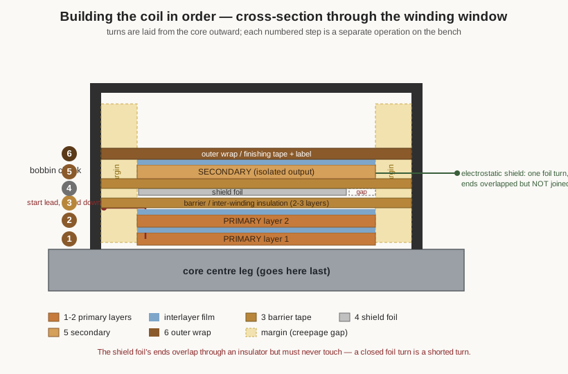
The margin is the strip of empty bobbin left at each end of every layer, between the outermost turn and the cheek, and it is pure creepage insulation. Creepage — the distance a leakage current would have to crawl along a surface to get from one winding to another, or from a winding to the core — is set on a layer-wound bobbin by how far the copper is kept back from the bobbin end. A generous margin, held by a few turns of margin tape built up at each end to the height of the winding, forces any surface leakage to travel the long way around and keeps the winding’s edge from creeping over the cheek and shorting to the next winding or the core. Volume 5 gives the creepage and clearance distances the safety standards demand between a mains winding and the output; the margin tape is how those distances are physically realised on the bobbin. Skimping the margin to fit a few more turns per layer is one of the classic ways an amateur-wound mains transformer fails its dielectric test.
Between the primary and the secondary goes the barrier — the inter-winding insulation, and on a mains transformer the single most important piece of insulation in the whole part, because it is the wall that keeps line potential off the isolated output the user touches. It is not one strip of interlayer film but several layers of tape, or a heavy polyester barrier film, built up thick enough and wide enough to meet the reinforced-insulation requirement between primary and secondary. It runs the full winding width including the margins, and it is laid with the same care as the interlayer film but more of it. Where the design calls for reinforced or double insulation — the standard for a mains transformer with no earthed screen between windings — the barrier is two independent insulation systems, each capable of withstanding the working voltage on its own, so that a flaw in one is caught by the other. This is the layer the hi-pot test at the end of the build exists to prove, and it is worth every minute spent laying it flat and full-width.
One optional layer belongs here: the electrostatic shield, a single turn of thin copper or aluminium foil laid over the primary, under the barrier, and connected by its own lead to earth. Its job is to intercept the capacitive coupling between primary and secondary, shunting high-frequency line noise to earth instead of letting it pass through the inter-winding capacitance into the output — the reason a shielded isolation transformer is quieter on sensitive equipment. The shield carries one subtle trap that the winder must never get wrong: its foil must wrap most of the way around the coil but its two ends must overlap through an insulator without touching, so that the foil is an open C and not a closed ring. A foil turn whose ends meet is a shorted turn — a single closed loop linking the core’s flux — and a shorted turn draws a heavy induced current, heats, and can destroy the transformer. The shield is grounded at one point only, by its own insulated lead; the overlap is taped so the ends can never migrate into contact. Drawn in cross-section, the shield is the one grey band with a deliberate gap in it.
11.5 The secondary and low-leakage sandwiches
With the barrier laid, the secondary is wound over it, in its own even layers with its own interlayer film, and finished with an outer wrap. For a low-current, high-voltage secondary this is much like winding the primary in miniature; for a high-current, low-voltage secondary — the heavy few-volt winding of a bench supply — the wire is thick, stiff, and hard to lay flat, and the winder trades fine-wire delicacy for the muscle to bend heavy copper cleanly around the bobbin and the patience to keep even a dozen fat turns square. Very heavy secondaries are sometimes wound as a flat copper strap or as several finer wires in parallel rather than one unmanageable conductor, both of which lay flatter and carry the current with less skin-effect penalty; the handling is different but the discipline — even, tight, insulated between layers — is the same.
Where the transformer’s leakage inductance matters — an audio output transformer, a tightly regulated supply, a switch-mode part — the simple primary-then-secondary stack is not good enough, and the winder builds an interleaved sandwich instead. Leakage inductance is the flux that links one winding but not the other, and it grows with the physical separation between primary and secondary; splitting the primary into two halves and putting the secondary between them — a primary-secondary-primary or P-S-P sandwich — roughly halves the leakage by roughly halving the mean separation, and finer subdivisions cut it further. Volume 5 and Volume 8 treat the leakage-inductance theory and the audio-transformer sandwich in detail; on the bench the P-S-P build is simply a more elaborate sequence of the same operations — wind half the primary, barrier, wind the secondary, barrier, wind the other half of the primary, each half’s turns counted so the two primary sections series-connect to the right total and the right phase. The counter tracks the turns per section; the winder tracks the phasing so the two half-primaries aid rather than oppose. The sandwich buys low leakage at the cost of more insulation interfaces to get right, and every one of those interfaces is a barrier the hi-pot test will probe.
11.6 Taps and leads
A tap is a connection brought out from a point partway along a winding without cutting the wire, so the winding continues unbroken past it, and it is how a mains primary offers 110-, 120-, 220-, and 240-volt connections, how a secondary offers a centre tap for a full-wave rectifier, and how a push-pull output transformer feeds its two tubes from a centre-tapped primary. Because the count sets the voltage, the tap is brought out at an exact turn: the machine is stopped on the tap turn — the counter is what lands it on the right voltage — and a loop of the continuous wire is pulled up above the winding. The neck of that loop is twisted so it cannot pull back into the winding, a length of insulating sleeving is slipped over the exposed loop so it cannot short to the turns it crosses, and the sleeved loop is taped down against the winding before the machine resumes. Volume 10’s Figure 4 shows the sequence; the point that bears repeating is that because the wire is never cut, the tap is a continuous conductor with a serviceable lead, not a soldered joint buried in the coil where it could fail unreachably.
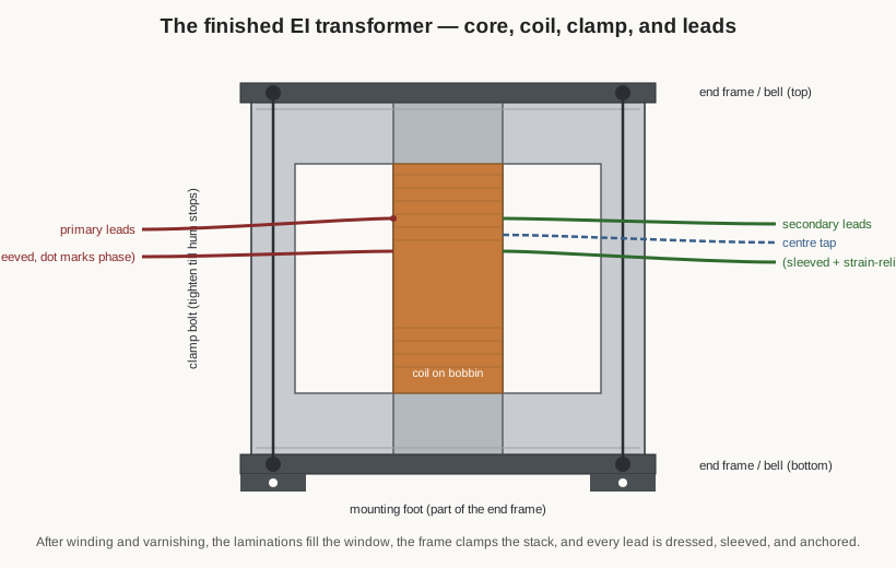
Leads — the start and finish of each winding and every tap — are what connect the coil to the outside world, and dressing them is where a tidy winder is separated from a careless one. Fine magnet wire is far too fragile to serve as a flying lead; it work-hardens and snaps at the first flex. So each lead is either a heavier stranded fly lead soldered to the magnet wire and the joint insulated and anchored, or the magnet wire itself sleeved in insulating tubing and given strain relief — anchored to the bobbin with tape or caught under a wrap — so that any pull on the lead is taken by the anchor and not by the delicate wire or its termination. Where a lead terminates on a bobbin pin, the enamel is stripped cleanly (thermally or mechanically), the copper tinned, and the lead soldered to the pin with a joint that is mechanically sound before it is electrically sound. A cold or starved solder joint on a transformer pin is a joint that will crack under thermal cycling and open the winding in service.
Two things must be tracked through all this lead work and never guessed: polarity and phasing. Volume 1 introduced the dot convention — the marks that say which winding ends are instantaneously the same polarity — and it exists precisely so that a transformer with multiple windings can be connected the right way round. A centre-tapped secondary wired backwards feeds a rectifier out of phase; two half-primaries of a sandwich connected in opposition cancel instead of add; two secondaries meant to series-add for a higher voltage subtract to nearly zero if their phase is reversed. The winder keeps the phasing straight by noting the winding direction and the start-and-finish of every section as it is wound, and by marking the leads accordingly, so that the finished transformer can be connected by its dots rather than by trial and error. A transformer whose leads are unmarked and whose phasing is unknown is a transformer that has to be re-derived on the test bench (Volume 13), and that is time paid to avoid five seconds of note-taking at the winder.
11.7 Finishing the coil
When the last winding is laid and its leads are out, the coil is finished with an outer wrap — a few turns of finishing tape over the whole winding that hold everything down, protect the outermost layer from abrasion, and give a clean surface to label. The wrap is snug but not so tight that it crushes the winding, and it stops short of the cheeks so it does not foul the core. Then the coil is labelled: which winding is which, the turn counts, the tap turns and voltages, the lead colours or pin numbers, and the phasing marks. On a one-off transformer this label is the winder’s only record of what is inside a coil that can never be inspected again once the core is in and the varnish is on; on a repeated build it is the check that this coil matches its siblings. The finished coil, wrapped and labelled, is now ready to be married to its core — and if the core is a stack of laminations, that marriage is the next operation.
11.8 Assembling the core: interleaving versus the butt gap
An EI transformer’s core is not a solid block but a stack of thin laminations, each a flat piece of grain-oriented silicon steel insulated from its neighbours to break up eddy currents (Volume 4). The laminations come in two mating shapes — the three-legged E and the closing bar I — and assembling the core means feeding these one at a time into the bobbin’s centre tube and outer windows until the stack fills the window, then clamping it. How the E and I pieces are arranged as they go in is one of the most consequential choices in the whole build, and it divides sharply by what the transformer is for.
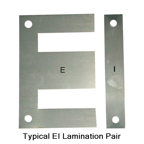
For an ordinary transformer the laminations are interleaved: the winder alternates the orientation of the E-I joint layer by layer, putting the E in from one side and the I closing it from the other on the first lamination, then flipping the arrangement on the next so the joint falls on the opposite side, and so on up the stack — the pattern called one-by-one, or a coarser two-by-two where pairs are alternated to speed the work. The purpose is to keep the magnetic path as continuous as possible. Every E-I joint is a tiny air gap where the flux must cross from one piece to another, and if all the joints lined up in one plane they would sum to one real gap across the whole core; by staggering the joints so each layer’s gap is bridged by the solid steel of the layers above and below, interleaving reduces the effective air gap to nearly nothing. A near-zero gap is what a normal transformer wants, because the gap sets the magnetizing current: the smaller the effective gap, the higher the core’s inductance, the smaller the exciting current, and the closer the real transformer comes to the ideal. An interleaved core also hums less, because there is no single concentrated gap for the flux to pull across with a vibrating force.
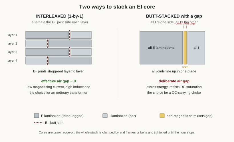
There is a case where the winder wants the opposite, and that is a transformer or inductor that must carry direct current — the choke in a power supply, the primary of a single-ended output transformer, any winding whose DC magnetizes the core toward saturation. Here the laminations are butt-stacked: all the E’s are assembled facing one way and all the I’s the other, so all the joints line up in a single plane, and a shim of non-magnetic material — a slip of paper, plastic, or brass of a calculated thickness — is inserted at that joint to set a deliberate air gap. The gap seems like a defect but it is the design: an air gap stores energy and, far more importantly, it dominates the magnetic circuit’s reluctance so that the DC bias current no longer drives the core into saturation. A choke with the right gap holds its inductance with a large DC current flowing where an ungapped core would have saturated and collapsed. Volume 4 gives the gap arithmetic; on the bench the distinction is simply interleave for AC, butt-stack with a shim for DC — and getting it backwards gives either a transformer that saturates or a choke with no useful inductance.
Whichever way the laminations go in, the stack is clamped. The assembled core is squeezed between end frames or bells — steel or aluminium brackets that cap the stack top and bottom and often carry the mounting feet — and drawn tight by through-bolts at the corners, or by a band, or by the frame’s own tabs. The clamping does two things: it holds the laminations in intimate contact so the magnetic path is solid, and it stops them vibrating against one another, which is the chief source of transformer hum. The classic bench instruction is to tighten the clamp until the hum stops — to energise the transformer (once it is safe to do so) and snug the bolts until the buzz of loose laminations quiets to the faint residual hum of magnetostriction in the steel itself, which no clamp can remove. A loose core is a noisy core; an over-clamped core can dish the laminations and stress the bobbin; the right clamp is firm and even.
11.9 Winding a toroid by hand
The toroid is the transformer whose core assembly happens before the winding, not after, because a toroid core is a single closed ring and there is no way to slide it into a pre-wound coil. The winding goes onto the ring directly, and that is a different craft entirely. Volume 10 described the shuttle machine that automates it for larger cores; but the smallest ferrite toroids — the RF transformers, the baluns and ununs, the little common-mode chokes whose holes are too small to admit any shuttle — are still wound by hand, and hand-winding a toroid is one of the genuine patience skills of the craft.
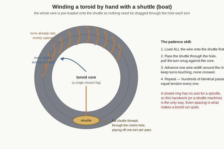
The problem the toroid sets is geometric: on every single turn the wire must pass through the central hole, and a spool of wire will not fit through the hole, so the entire length of wire for the winding has to be got to the other side of the ring for each turn. The naive method — threading the whole free end through the hole and pulling it snug, turn after turn — works but means dragging the entire remaining wire through the donut every time, and it is agonisingly slow. The hand winder’s tool is a shuttle (also called a boat or a winding needle): a flat carrier onto which all the wire for the core is first wound, small enough to pass through the hole. The loaded shuttle is passed through the hole and around the outside, over and over, paying off one turn onto the core per pass, so the wire is carried through the hole a little at a time on the shuttle instead of being dragged whole. It is still one pass per turn, still patient work, but each pass is quick.
Three disciplines make a good hand-wound toroid. The first is even tension: each turn pulled snug against the core with the same firmness, so no turn is loose enough to buzz and none tight enough to bite into the ring’s coating or the turn beside it. The second is even spacing: the turns marched around the ring so they cover it uniformly, neither bunched at one arc nor gapped at another, because uneven spacing raises leakage and, on a power toroid, is part of why a badly wound one hums where a well-wound one is silent. The third is simply keeping count and keeping the turns from crossing — hard on a ring where there is no traverse and no cheek to lay against, only the winder’s eye and hand. Where the toroid carries more than one winding — a two-winding power toroid, a balun’s several windings — the same rules apply per winding, with insulation between where the isolation demands it, and the phasing tracked just as carefully as on a bobbin. A toroid rewards the patience it demands: a cleanly hand-wound ring is a compact, quiet, low-leakage transformer that no bobbin-and-lamination part can quite match.
11.10 Varnish and impregnation
A newly wound and assembled transformer is mechanically loose in a way that will not survive service. The turns can still move minutely against one another and against the core; the windings can absorb moisture from the air; and the many small air spaces between turns are poor conductors of the heat the copper generates. Impregnation cures all three at once by filling the winding with an insulating resin or varnish and then curing it hard, so the whole coil becomes a solid monolithic block. There are three levels of it, in rising order of thoroughness.
The simplest is a dip-and-bake: the finished transformer is dipped into a bath of insulating varnish, left until the varnish has soaked in as far as capillary action will draw it, lifted out to drain, and then baked in an oven to drive off the solvent and cure the resin. It is cheap, needs no special equipment beyond a bath and an oven, and is entirely adequate for many small transformers. Its limit is that dipping alone does not drive the varnish into the tightest interstices deep in the winding, where trapped air keeps the resin out.
The thorough method is vacuum-pressure impregnation, or VPI. The transformer is placed in a chamber, the chamber is evacuated to pull the air out of the winding’s every crevice, the insulating resin is admitted under that vacuum so it is drawn into the spaces the air has left, and then the chamber is pressurised to force the resin the rest of the way in, filling the winding completely before it is drained and baked. VPI leaves essentially no voids, and a void-free winding is one with no trapped air to ionise under voltage stress, no path for moisture, and the best possible heat conduction from the copper out to the surface. It is the professional standard for anything that must run hard or last long, and it is why a factory-impregnated transformer outlasts a hand-dipped one.
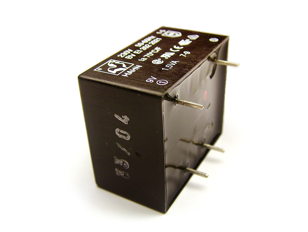
Whatever the method, the bake is not optional — it is the step that actually cures the resin from a sticky liquid into a hard, permanent solid, and it also drives out the last of any absorbed moisture. The payoff of a properly impregnated transformer is worth listing, because each item answers a real failure mode. It locks the turns so they cannot vibrate, which kills the mechanical hum that loose windings add to the core’s own. It excludes moisture, which would otherwise lower the insulation resistance and, over years, corrode fine copper and degrade the insulation. It improves heat transfer, because solid resin conducts heat far better than the trapped air it replaces, so the winding runs cooler for the same load. And it reinforces the insulation, filling the tiny voids where a high-voltage stress would otherwise find air to break down. A transformer that hums, runs hot, or slowly loses its insulation is often one that was never properly impregnated. For a potting-level encapsulation — a transformer cast solid in a filled resin block, as in the figure — the same benefits are taken to their extreme, at the cost of a part that can never be opened or repaired.
11.11 The safety finish: hi-pot and insulation resistance
A mains transformer is a safety-critical device: its primary sits at line potential, and the insulation between primary and secondary is what stands between that potential and whoever touches the output. A newly wound transformer’s insulation looks fine, but a nicked strand of enamel, a wrinkled barrier, a skimped margin, or a void the varnish missed is invisible to the eye and lethal in service. The finish of the build is therefore not the varnish but the proof — two electrical tests that verify the insulation before the transformer is ever energised. Volume 13 treats the test methods in full; the point here is that these tests belong to the build, done before first power-up, not to some later maintenance.
The first is the insulation-resistance test, made with a low-voltage source — typically 500 to 1000 volts DC from an insulation tester, a “megger” — applied between primary and secondary (and between each winding and the core), measuring the resistance of the insulation, which for sound insulation should read in the tens or hundreds of megohms or higher. A low reading means a leakage path — moisture, contamination, or damaged insulation — and condemns the coil before any high voltage is applied to it. It is the gentle first check that says the insulation is at least basically intact.
The second, and the real safety gate, is the dielectric-withstand or hi-pot test: a high AC voltage — far above the working voltage — applied for a defined time between primary and secondary, and again between windings and core, to prove that the barrier can hold off a fault-level voltage without breaking down. The standards fix the level: the common rule is twice the working voltage plus a further thousand volts, so a 230-volt mains winding is proof-tested at roughly 1500 volts, and a reinforced primary-to-secondary barrier at a higher figure still — often three thousand volts or more for a double-insulated mains part. The production version of the test is applied for one second (or a couple of seconds at a raised voltage), the type-test version for a full minute; the winding passes if no breakdown and no excessive leakage current occurs, and fails — audibly and often destructively — if the barrier arcs over. Passing the hi-pot is what licenses the transformer to be plugged in.
The danger of skipping this finish cannot be overstated, and it is the reason the winding volumes labour the insulation so hard. A home-wound mains transformer that has never been hi-pot tested is a transformer whose safety barrier has been assumed rather than proven, and the first time it is proven is when a fault puts line voltage onto the output and, possibly, onto a person. The test is cheap, quick, and the only honest way to know that the margins were wide enough, the barrier full-width, the enamel unnicked, and the varnish void-free. A winder who lays a beautiful coil and then energises it without the hi-pot has done the easy ninety per cent and skipped the ten per cent that was the point. Volume 5 sets the creepage and clearance that make a transformer capable of passing; this test confirms that the particular coil on the bench actually did.
11.12 Common mistakes and how to avoid each
Most of the ways a hand-wound transformer goes wrong are avoidable, and naming them is the fastest way to avoid them. Loose, bulging turns come from too little tension or a wandering lay; they overfill the window so the core will not close, and they present a lumpy surface the insulation cannot lie flat on. The cure is constant, firm tension and a disciplined traverse, and checking the build height against the window budget as the coil grows. Nicked or scraped enamel comes from over-tension dragging the wire across the bobbin edge, from a rough guide eyelet, or from a snag not caught in time; it plants a fault that the hi-pot test will later find, or worse, that it will miss until service. The cure is gentle tension, smooth hardware, watchful fingers, and — the backstop — the hi-pot test that catches what the eye missed.
The wrong interleave is the core mistake that hides in plain sight: interleaving a core that should have been butt-stacked with a gap gives a choke that saturates under its DC load, and butt-stacking with a gap a transformer that should have been interleaved gives a normal transformer a needless gap, a swollen magnetizing current, and extra hum. The cure is to know, before assembly, whether the part carries DC (butt-stack with a shim) or not (interleave). An insufficient margin — copper laid too close to the cheek to squeeze in more turns — shortens the creepage path and is a classic cause of a failed dielectric test; the cure is to build the margin tape to the design’s creepage distance and never rob it for turns. A shorted shield turn — the electrostatic foil’s ends allowed to touch and close the loop — turns a noise shield into a heating single-turn winding that can cook the transformer; the cure is to overlap the foil ends through an insulator and ground the shield at one point only.
And the mistake that undoes all the others’ cures is skipping the hi-pot. Every good habit above — the tension, the margins, the full-width barrier, the impregnation — exists to make the transformer able to pass the dielectric test; declining to run the test throws away the one independent check that they worked. The discipline is simple and worth restating as the volume closes: wind clean and even, insulate generously and full-width, interleave or gap the core according to whether DC flows, impregnate to lock and seal the coil, and prove the safety barrier with an insulation-resistance and a hi-pot test before the transformer is ever plugged in.
11.13 Where this leads
This volume has taken the machine of the previous one and put a builder’s hands on it: preparing the bobbin and reading the layer count off the design; anchoring the start and winding the primary as even, counted, correctly tensioned layers; interleaving the film, keeping the margins for creepage, laying the full-width barrier, and adding the open-ended electrostatic shield; winding the secondary — or building the low-leakage P-S-P sandwich — over that barrier; bringing out taps at exact turns and dressing every lead with strain relief, clean solder, and the phasing kept straight by the dots; finishing and labelling the coil; assembling the core by interleaving for an ordinary transformer or butt-stacking with a shim gap for a DC-carrying choke, then clamping until the hum stops; winding the closed toroid by hand with a shuttle when no machine will thread it; impregnating the finished part by dip-and-bake or full VPI to lock the turns, seal out moisture, and carry away the heat; and — the finish that matters most — proving the safety barrier with an insulation-resistance and a hi-pot test before first power.
Everything so far has been technique in the general. The next volume puts it to work on real parts: a mains power transformer rewound from a salvaged core, a quiet toroidal power transformer, a tube output transformer with its low-leakage sandwich, a one-to-one isolation transformer, a current-sense CT, and a broadband antenna balun or unun on a ferrite core — each a worked build that exercises the primary-and-secondary sequence, the interleaving, the taps and leads, the core assembly, and the safety finish laid out here. And the volume after that takes each finished transformer to the test bench and measures it — turns ratio, winding resistance, magnetizing and leakage inductance, the open- and short-circuit tests, the polarity and phasing, and the hi-pot that this volume has insisted on — closing the loop from the design sheet, through the winder’s hands, to a proven, safe, working transformer.
Comments (0)